Table of Contents for
Mastering OpenLayers 3
 Mastering OpenLayers 3
Published by
Packt Publishing, 2016
Mastering OpenLayers 3
Published by
Packt Publishing, 2016
- Cover
- Table of Contents
- Mastering OpenLayers 3
- Mastering OpenLayers 3
- Credits
- About the Author
- About the Reviewer
- www.PacktPub.com
- Preface
- What you need for this book
- Who this book is for
- Conventions
- Reader feedback
- Customer support
- 1. Creating Simple Maps with OpenLayers 3
- Structure of OpenLayers 3
- Building the layout
- Using the API documentation
- Debugging the code
- Summary
- 2. Applying Custom Styles
- Customizing the default appearance
- Styling vector layers
- Customizing the appearance with JavaScript
- Creating a WebGIS client layout
- Summary
- 3. Working with Layers
- Building a layer tree
- Adding layers dynamically
- Adding vector layers with the File API
- Adding vector layers with a library
- Removing layers dynamically
- Changing layer attributes
- Changing the layer order with the Drag and Drop API
- Clearing the message bar
- Summary
- 4. Using Vector Data
- Accessing attributes
- Setting attributes
- Validating attributes
- Creating thematic layers
- Saving vector data
- Saving with WFS-T
- Modifying the geometry
- Summary
- 5. Creating Responsive Applications with Interactions and Controls
- Building the toolbar
- Mapping interactions to controls
- Building a set of feature selection controls
- Adding new vector layers
- Building a set of drawing tools
- Modifying and snapping to features
- Creating new interactions
- Building a measuring control
- Summary
- 6. Controlling the Map – View and Projection
- Customizing a view
- Constraining a view
- Creating a navigation history
- Working with extents
- Rotating a view
- Changing the map's projection
- Creating custom animations
- Summary
- 7. Mastering Renderers
- Using different renderers
- Creating a WebGL map
- Drawing lines and polygons with WebGL
- Blending layers
- Clipping layers
- Exporting a map
- Creating a raster calculator
- Creating a convolution matrix
- Clipping a layer with WebGL
- Summary
- 8. OpenLayers 3 for Mobile
- Responsive styling with CSS
- Generating geocaches
- Adding device-dependent controls
- Vectorizing the mobile version
- Making the mobile application interactive
- Summary
- 9. Tools of the Trade – Integrating Third-Party Applications
- Exporting a QGIS project
- Importing shapefiles
- Spatial analysis with Turf
- Spatial analysis with JSTS
- 3D rendering with Cesium
- Summary
- 10. Compiling Custom Builds with Closure
- Configuring Node JS
- Compiling OpenLayers 3
- Bundling an application with OpenLayers 3
- Extending OpenLayers 3
- Creating rich documentation with JSDoc
- Summary
- Index
In the last example, called ch07_clip_webgl, we will go through some of the key aspects of working with WebGL and OpenLayers 3. WebGL is an exceptionally rich JavaScript port of OpenGL, which is capable of performing advanced 3D GPU calculations. However, as the OpenLayers 3 library already uses it and parameterizes it, when we use the WebGL renderer in the precompose and postcompose rendering hooks, we have only a limited number of possibilities. For example, OpenGL can automatically blend textures into each other with some blending options. However, as OpenLayers 3 already uses this capability in order to draw the layers on each other with a possible transparency option, we cannot change the global blending property without messing up the entire rendering process.
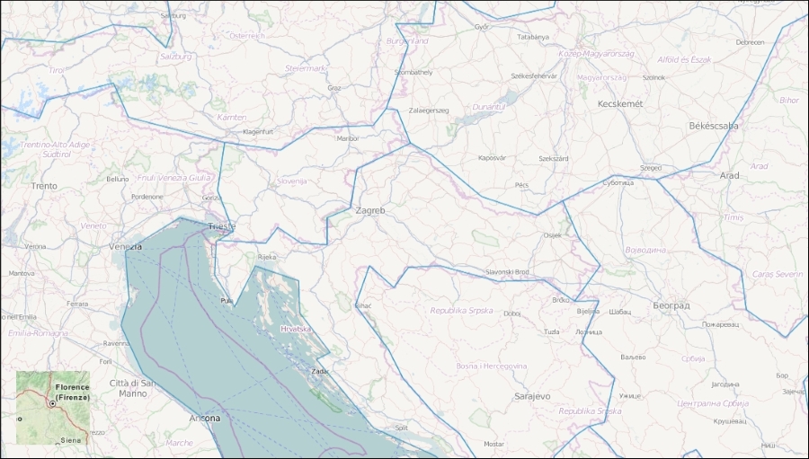
Clipping, or in this case, masking parts of a layer, is a possible WebGL operation with the library. Our goal is identical to the previous clipping example: we create a 100 x 100 pixels peeking window, which displays a silently added layer above our other layers.
Note
This part can be considered as a bonus example, in which, we will learn about some of the fundamental aspects of WebGL programming. Unfortunately, covering the entire basics of WebGL is out of the scope of this book. There are great sources on the Internet if additional reference is needed. One of the greatest tutorials out there can be found at http://webglfundamentals.org/.
When we operate with WebGL, we have to deal with two entirely different concepts. First, we need some OpenGL programs, which are transferred and run by the GPU. If we have our programs up and running, we can parameterize them and communicate with them through JavaScript. In JavaScript, we can set global flags and attributes, and send shapes (primitives), colors, textures, and other things to the GPU for rendering.
There are two kinds of programs we can create with WebGL. The first one, the vertex shader, is a vector program, which is responsible for drawing shapes based on vector coordinates. The second one, called fragment shader, is a raster program. It defines the color of the drawn shapes. In this example, we do not need to color the mask; therefore, our fragment shader is an empty function, although, we can define the precision of our calculations. In OpenLayers 3, the default precision is medium because it is sufficient for texture rendering; however, if we need to create a high-precision WebGL extension, we can define it as precision highp float:
var fragmentShaderSource = [
    'precision mediump float;',
    'void main() {',
    '}'
].join('');
Tip
As you can see, when we provide a program, we have to write it as a single string in the language of OpenGL (GLSL), which is similar to the C language. Unlike JavaScript, this language is strongly typed; therefore, make sure that you always work with the right type when you create or assign variables.
Next, we create the vertex shader program, which is a little more tricky. First, we have two variables: one for the position of the current drawing (cursor) and the other for the resolution of the canvas. The resolution is very important as OpenGL uses a clipping space when it draws on the canvas, which ranges from -1 to 1. It is DPI-independent, and as we would like to define our peeking window in pixels, rather than in percentage values, we have to convert the absolute pixel values that we will provide to the clipping space values:
var vertexShaderSource = [
    'attribute vec2 a_position;',
    'uniform vec2 u_resolution;',
    'void main() {',
    '    vec2 pixelPos = a_position / u_resolution * 2.0 - 1.0;',
    '    gl_Position = vec4(pixelPos, 0, 1);',
    '}'
].join('');
Variables in GLSL are similar to C declarations. There are, however, qualified variables with special meanings. From the four types (const, attribute, uniform, and varying), we've used two. A variable with the attribute qualifier can only be used by the vertex shader, and it is read only by the shader. It can be modified between drawing vertices; therefore, it is great for the updating of the position of the cursor. Variables with the uniform qualifier can be used by both of the shaders but can only be updated between drawing primitives. This peculiarity makes this type suitable for us to store the resolution of our canvas.
This conversion is a three-step task. First, we divide the pixel position by the resolution of our canvas, getting a value between 0 and 1. Then, we stretch the interval to 2 by multiplying the value. Finally, we clamp the stretched interval between -1 and 1 (the clipping space) by subtracting 1 from the result. Next, we update the position of the OpenGL cursor with our calculated clipping space position, and we're finally done.
Note
Note that we have to provide the OpenGL programs in a string format. This can be done by concatenating the lines of the program, but the official OpenLayers 3 WebGL clipping example provided a nice, more readable method for this purpose, which we could adapt. This method uses an array of lines and concatenates them right after the array is filled with content.
Now that we have some programs for OpenGL, we can proceed and use them to clip our layer. The procedure starts similarly to the previous clipping example. We create a layer and register some events to its rendering hooks. The only significant difference is that we use WebGL methods to clip the layer this time. First, we create the layer:
var clippedLayer = new ol.layer.Tile({
    source: new ol.source.MapQuest({
        layer: 'osm'
    }),
    zIndex: 9999
});
Next, we attach a precompose event to it. Before the layer is drawn on the canvas, we initialize our mask using a WebGL stencil. First things first: we construct some proper shader programs from the program strings, create a WebGL program, and attach the shaders to it. We also link our complete program to the context:
clippedLayer.on('precompose', function (evt) {
    var context = evt.glContext;
    var gl = context.getGL();
    var program = gl.createProgram();

    var vertexShader = gl.createShader(gl.VERTEX_SHADER);
    gl.shaderSource(vertexShader, vertexShaderSource);
    gl.compileShader(vertexShader);
    gl.attachShader(program, vertexShader);

    var fragmentShader = gl.createShader(gl.FRAGMENT_SHADER);
    gl.shaderSource(fragmentShader, fragmentShaderSource);
    gl.compileShader(fragmentShader);
    gl.attachShader(program, fragmentShader);

    gl.linkProgram(program);
    context.useProgram(program);
Next, we save the qualified variables of our vertex shader to JavaScript variables. This operation asks for the memory space where these variables are stored. After this, those memory spaces are mapped to JavaScript variables from where everything is handled by the browser's JavaScript engine:
    var resolutionLocation = gl.getUniformLocation(program, 'u_resolution');
    gl.uniform2f(resolutionLocation, context.A.width, context.A.height);
    var positionLocation = gl.getAttribLocation(program, 'a_position');
In the second line, we provide our canvas's width and height to the OpenGL program as the resolution variable. Note that OpenLayers 3 does not expose the canvas element when the WebGL renderer is used; it does this only when the canvas renderer is in action. It is stored, however, and can be accessed from the context object's A property.
Let's stop here a little bit and think about the second line. We spoke a little about passing the resolution of the canvas to OpenGL, but we passed our canvas's height and width. That's right; we do not use resolution in its cartographic or geoinformatic meaning. We send the dimensions of our canvas to the GPU. Take a look at the vertex shader again. The resolution variable is a vec2 type, which is a simple numeric array with two members. As the clipping space ranges from -1 to 1 in every dimension, we can only calculate the clipping space coordinates from the pixel coordinates in one command in this way. As the position variable and result variable have matching types, we can execute arithmetic operations on the entire arrays. OpenGL will automatically iterate through them and perform the operations on the corresponding members. In the next step, we initialize our stencil test:
    gl.enable(gl.STENCIL_TEST);
    gl.colorMask(false, false, false, false);
    gl.stencilOp(gl.KEEP, gl.KEEP, gl.REPLACE);
    gl.stencilFunc(gl.ALWAYS, 1, 255);
We enable stencil testing, and set the color mask to false in every color band (RGBA). We do this as we do not want to draw anything on the canvas; therefore, we do not need the fragment shader to apply colors to our shapes. We only want to create a square to mask some pixels. The stencil is initialized with a stencil operation and a stencil function. The stencil operation needs to know what should be done in the three different test results. If our stencil test fails, we will keep the original value. If our stencil test passes but the depth test fails (there is a layer above the peeking window), we will also keep the original value. Finally, if both of the tests pass, we will replace the original value.
Now, we need a stencil function that determines the conditions under which the stencil test can pass. In our case, the stencil test should be always passed when a pixel is in the peeking window. The second argument is called the reference value. It contains a value that is compared to every pixel if we use a comparison function in the first argument. It also represents the replace value if we call gl.REPLACE in our stencil operation. The third value is the mask. Both the reference and the original values are bitwise AND-ed with it before comparison. As a direct comparison is enough for us, we use a 255 mask value. After these operations, our stencil buffer is initialized with a bunch of 0 values, and every pixel will get a 1 value from the shapes using which we will draw from now on.
Next, we draw our rectangle, which will act as a stencil for the peeking window layer:
    var buffer = gl.createBuffer();
    gl.bindBuffer(gl.ARRAY_BUFFER, buffer);
    gl.bufferData(gl.ARRAY_BUFFER, new Float32Array([
      20, 20, 120, 20, 20, 120, 120, 120
    ]), gl.STATIC_DRAW);
In OpenGL, when we want to provide an array of vertices or colors, we need to do this with a vertex buffer. This is a simple typed array from the aspect of JavaScript, containing the values of the provided data. First, we create an empty buffer. Then, we link it to our program and fill it with values. This is another tricky part. We have to create a square but as a primitive. However, only points, lines, and triangles can be drawn as primitives in OpenGL. This way, we have to create an array with the vertex coordinates of two triangles building a square.
Now, things get a little interesting. If you look at the array, it does not contain six pairs of coordinates, which would be required for three triangles; it only contains four pairs. OpenGL can draw three kinds of triangles. If we have triangles with shared line segments, we can draw triangle strips. This method allows code not being redundant, and only pass the final point of the second triangle without repeating the shared segment. Now, we draw our triangles:
    gl.enableVertexAttribArray(positionLocation);
    gl.vertexAttribPointer(positionLocation, 2, gl.FLOAT, false, 0, 0);
    gl.drawArrays(gl.TRIANGLE_STRIP, 0, 4);
First, we turn on our cursor with the position attribute of our vertex shader. Next, we set the metadata of our vertex buffer. The index will be stored in the position attribute. The size of the coordinates is two (two dimensional coordinates); the type of the coordinates is a floating point since they aren't normalized, and finally, their stride and offset are 0. Now that OpenGL knows everything about our triangles, we can instruct it to draw them.
As we have our stencil initialized at this point, the only thing we have to do is prepare it to mask the pending content:
    gl.bindBuffer(gl.ARRAY_BUFFER, null);
    gl.deleteBuffer(buffer);

    gl.colorMask(true, true, true, true);
    gl.stencilFunc(gl.NOTEQUAL, 0, 255);
});
We remove the vertex buffer containing the vertices of our triangles as we do not need it anymore. Next, we override the stencil function. From now on, we only keep values that do not result in a 0 after the stencil test. Remember: in the square, every value is 1; outside of it, every value is 0. Finally, we register an event listener to the layer's postcompose event and add it to the map silently:
clippedLayer.on('postcompose', function (evt) {
    var context = evt.glContext;
    var gl = context.getGL();
    gl.disable(gl.STENCIL_TEST);
});
clippedLayer.setMap(map);
After the layer has been rendered, we simply disable the stencil testing, allowing the library to properly render any other pending content. If you save the code and look it up in a browser, you will see our peeking window rendered entirely with WebGL: