Table of Contents for
Practical UNIX and Internet Security, 3rd Edition
 Practical UNIX and Internet Security, 3rd Edition
Published by
O'Reilly Media, Inc., 2003
Practical UNIX and Internet Security, 3rd Edition
Published by
O'Reilly Media, Inc., 2003
- Cover
- Practical Unix & Internet Security, 3rd Edition
- A Note Regarding Supplemental Files
- Preface
- Unix “Security”?
- Scope of This Book
- Which Unix System?
- Conventions Used in This Book
- Comments and Questions
- Acknowledgments
- A Note to Would-Be Attackers
- I. Computer Security Basics
- 1. Introduction: Some Fundamental Questions
- What Is Computer Security?
- What Is an Operating System?
- What Is a Deployment Environment?
- Summary
- 2. Unix History and Lineage
- History of Unix
- Security and Unix
- Role of This Book
- Summary
- 3. Policies and Guidelines
- Planning Your Security Needs
- Risk Assessment
- Cost-Benefit Analysis and Best Practices
- Policy
- Compliance Audits
- Outsourcing Options
- The Problem with Security Through Obscurity
- Summary
- II. Security Building Blocks
- 4. Users, Passwords, and Authentication
- Logging in with Usernames and Passwords
- The Care and Feeding of Passwords
- How Unix Implements Passwords
- Network Account and Authorization Systems
- Pluggable Authentication Modules (PAM)
- Summary
- 5. Users, Groups, and the Superuser
- Users and Groups
- The Superuser (root)
- The su Command: Changing Who You Claim to Be
- Restrictions on the Superuser
- Summary
- 6. Filesystems and Security
- Understanding Filesystems
- File Attributes and Permissions
- chmod: Changing a File’s Permissions
- The umask
- SUID and SGID
- Device Files
- Changing a File’s Owner or Group
- Summary
- 7. Cryptography Basics
- Understanding Cryptography
- Symmetric Key Algorithms
- Public Key Algorithms
- Message Digest Functions
- Summary
- 8. Physical Security for Servers
- Planning for the Forgotten Threats
- Protecting Computer Hardware
- Preventing Theft
- Protecting Your Data
- Story: A Failed Site Inspection
- Summary
- 9. Personnel Security
- Background Checks
- On the Job
- Departure
- Other People
- Summary
- III. Network and Internet Security
- 10. Modems and Dialup Security
- Modems: Theory of Operation
- Modems and Security
- Modems and Unix
- Additional Security for Modems
- Summary
- 11. TCP/IP Networks
- Networking
- IP: The Internet Protocol
- IP Security
- Summary
- 12. Securing TCP and UDP Services
- Understanding Unix Internet Servers and Services
- Controlling Access to Servers
- Primary Unix Network Services
- Managing Services Securely
- Putting It All Together: An Example
- Summary
- 13. Sun RPC
- Remote Procedure Call (RPC)
- Secure RPC (AUTH_DES)
- Summary
- 14. Network-Based Authentication Systems
- Sun’s Network Information Service (NIS)
- Sun’s NIS+
- Kerberos
- LDAP
- Other Network Authentication Systems
- Summary
- 15. Network Filesystems
- Understanding NFS
- Server-Side NFS Security
- Client-Side NFS Security
- Improving NFS Security
- Some Last Comments on NFS
- Understanding SMB
- Summary
- 16. Secure Programming Techniques
- One Bug Can Ruin Your Whole Day . . .
- Tips on Avoiding Security-Related Bugs
- Tips on Writing Network Programs
- Tips on Writing SUID/SGID Programs
- Using chroot( )
- Tips on Using Passwords
- Tips on Generating Random Numbers
- Summary
- IV. Secure Operations
- 17. Keeping Up to Date
- Software Management Systems
- Updating System Software
- Summary
- 18. Backups
- Why Make Backups?
- Backing Up System Files
- Software for Backups
- Summary
- 19. Defending Accounts
- Dangerous Accounts
- Monitoring File Format
- Restricting Logins
- Managing Dormant Accounts
- Protecting the root Account
- One-Time Passwords
- Administrative Techniques for Conventional Passwords
- Intrusion Detection Systems
- Summary
- 20. Integrity Management
- The Need for Integrity
- Protecting Integrity
- Detecting Changes After the Fact
- Integrity-Checking Tools
- Summary
- 21. Auditing, Logging, and Forensics
- Unix Log File Utilities
- Process Accounting: The acct/pacct File
- Program-Specific Log Files
- Designing a Site-Wide Log Policy
- Handwritten Logs
- Managing Log Files
- Unix Forensics
- Summary
- V. Handling Security Incidents
- 22. Discovering a Break-in
- Prelude
- Discovering an Intruder
- Cleaning Up After the Intruder
- Case Studies
- Summary
- 23. Protecting Against Programmed Threats
- Programmed Threats: Definitions
- Damage
- Authors
- Entry
- Protecting Yourself
- Preventing Attacks
- Summary
- 24. Denial of Service Attacks and Solutions
- Types of Attacks
- Destructive Attacks
- Overload Attacks
- Network Denial of Service Attacks
- Summary
- 25. Computer Crime
- Your Legal Options After a Break-in
- Criminal Hazards
- Criminal Subject Matter
- Summary
- 26. Who Do You Trust?
- Can You Trust Your Computer?
- Can You Trust Your Suppliers?
- Can You Trust People?
- Summary
- VI. Appendixes
- A. Unix Security Checklist
- Preface
- Chapter 1: Introduction: Some Fundamental Questions
- Chapter 2: Unix History and Lineage
- Chapter 3: Policies and Guidelines
- Chapter 4: Users, Passwords, and Authentication
- Chapter 5: Users, Groups, and the Superuser
- Chapter 6: Filesystems and Security
- Chapter 7: Cryptography Basics
- Chapter 8: Physical Security for Servers
- Chapter 9: Personnel Security
- Chapter 10: Modems and Dialup Security
- Chapter 11: TCP/IP Networks
- Chapter 12: Securing TCP and UDP Services
- Chapter 13: Sun RPC
- Chapter 14: Network-Based Authentication Systems
- Chapter 15: Network Filesystems
- Chapter 16: Secure Programming Techniques
- Chapter 17: Keeping Up to Date
- Chapter 18: Backups
- Chapter 19: Defending Accounts
- Chapter 20: Integrity Management
- Chapter 21: Auditing, Logging, and Forensics
- Chapter 22: Discovering a Break-In
- Chapter 23: Protecting Against Programmed Threats
- Chapter 24: Denial of Service Attacks and Solutions
- Chapter 25: Computer Crime
- Chapter 26: Who Do You Trust?
- Appendix A: Unix Security Checklist
- Appendix B: Unix Processes
- Appendixes C, D, and E: Paper Sources, Electronic Sources, and Organizations
- B. Unix Processes
- About Processes
- Signals
- Controlling and Examining Processes
- Starting Up Unix and Logging In
- C. Paper Sources
- Unix Security References
- Other Computer References
- D. Electronic Resources
- Mailing Lists
- Web Sites
- Usenet Groups
- Software Resources
- E. Organizations
- Professional Organizations
- U.S. Government Organizations
- Emergency Response Organizations
- Index
- Index
- Index
- Index
- Index
- Index
- Index
- Index
- Index
- Index
- Index
- Index
- Index
- Index
- Index
- Index
- Index
- Index
- Index
- Index
- Index
- Index
- Index
- Index
- Index
- Index
- Index
- About the Authors
- Colophon
- Copyright
Modems are devices that let computers transmit information over ordinary telephone lines. The word explains how the device works: modem is an acronym for “modulator/demodulator.” Modems translate a stream of information into a series of tones (modulation) at one end of the telephone line, and translate the tones back into the serial stream at the other end of the connection (demodulation). Most modems are bidirectional —every modem contains both a modulator and a demodulator, so a data transfer can take place in both directions simultaneously.
Modems have a flexibility that is unparalleled by other communications technologies. Because modems work with standard telephone lines, and use the public telephone network to route their conversations, any computer that is equipped with a modem and a telephone line can communicate with any other computer that has a modem and a telephone line, anywhere in the world. Modems thus bypass firewalls, packet filters, and intrusion detection systems.
What’s more, even in this age of corporate LANs, cable modems, and DSL links, dialup modems are still the single most common way that people access the Internet. This trend is likely to continue through the first decade of the 21st century because dialup access is dramatically cheaper to offer than high-speed, always-on services.
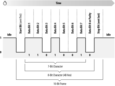
Information inside most computers moves in packets of 8, 16, 32, or 64 bits at a time, using 8, 16, 32, or 64 individual wires. When information leaves a computer, however, it is often organized into a series of single bits that are transmitted sequentially. Often, these bits are grouped into 8-bit bytes for purposes of error checking or special encoding. Serial interfaces transmit information as a series of pulses over a single wire. A special pulse called the start bit signifies the start of each character. The data is then sent down the wire, one bit at a time, after which another special pulse called the stop bit is sent (see Figure 10-1) .
Because a serial interface can be set up with only three wires (transmit data, receive data, and ground), it’s often used with terminals. With additional wires, serial interfaces can be used to control modems, allowing computers to make and receive telephone calls.
One of the most common serial interfaces is based on the RS-232 standard. This standard was developed to allow individuals to use remote computer systems over dialup telephone lines with remote terminals. The standard includes provisions for a remote terminal that is connected to a modem that places a telephone call, a modem that answers the telephone call, and a computer that is connected to that modem. The terminal can be connected directly to the computer, eliminating the need for two modems, through the use of a special device called a null modem adapter. Sometimes this device is built directly into a cable, in which case the cable is called a null modem cable.
Tip
Universal Serial Bus (USB), Firewire, and even Ethernet are all high-speed serial systems that use low-level serial protocols to transport packets from which higher-level protocols are built. This chapter does not concern itself with these serial interfaces.
The basic configuration of a terminal and a computer connected by two modems is shown in Figure 10-2.
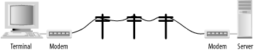
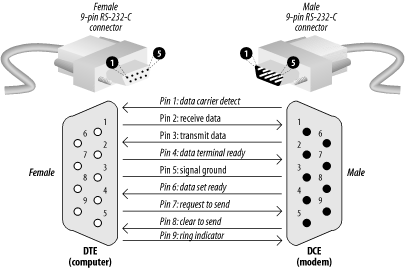
The computer and terminal are called data terminal equipment (DTE), while the modems are called data communication equipment (DCE). The standard RS-232 connector is a 25-pin D-shell type connector; only 9 pins are used to connect the DTE and DCE sides together.
Of these nine pins, only transmit data (pin 2), receive data (pin 3), and signal ground (pin 7) are needed for directly wired communications. Five pins (2, 3, 7, 8, and 20) are needed for proper operation of modems (although most also use pins 4 and 5). Frame ground (pin 1) was originally used to connect electrically the physical frame (chassis) of the DCE and the frame of the DTE to reduce electrical hazards and static.
Because only 8 pins of the 25-pin RS-232 connector are used, the computer industry has largely moved to smaller connectors that follow the 9-pin RS-232-C standard. Most PCs are equipped with this 9-pin RS-232-C connector, shown in Figure 10-3.
The pinouts for the 25-pin RS-232 and 9-pin RS-232-C are both summarized in Table 10-1.
Table 10-1. RS-232 pin assignments for a 25-pin connector
|
25-pin RS-232 location |
9-pin RS-232-C location |
Code |
Name |
Description |
|---|---|---|---|---|
|
1 |
n/a |
FG |
Chassis ground of equipment. (Note: this pin is historical; modern systems don’t connect the electrical ground of different components together because such a connection causes more problems than it solves.) | |
|
2 |
3 |
TD (or TxD) |
Data transmitted from the computer or terminal to the modem. | |
|
3 |
2 |
RD (or RxD) |
Data transmitted from the modem to the computer. | |
|
4 |
7 |
RTS |
Tells the modem when it can transmit data. Sometimes the computer is busy and needs to have the modem wait before the next character is transmitted. Used for “hardware flow control.” | |
|
5 |
8 |
CTS |
Tells the computer when it’s OK to transmit data. Sometimes the modem is busy and needs to have the computer wait before the next character is transmitted. Used for “hardware flow control.” | |
|
6 |
6 |
DSR |
Tells the computer that the modem is turned on. The computer should not send the modem commands if this signal is not present. | |
|
7 |
5 |
SG |
Reference point for all signal voltages. | |
|
8 |
1 |
DCD |
Tells the computer that the modem is connected by telephone with
another modem. Unix may use this signal to
tell it when to display a | |
|
20 |
4 |
DTR |
Tells the modem that the computer is turned on and ready to accept connections. The modem should not answer the telephone—and it should automatically hang up on an established conversation—if this signal is not present. | |
|
22 |
9 |
RI |
Tells the computer that the telephone isringing. |
A number of nonstandard RS-232 connectors are also in use. The Apple Macintosh computer uses a circular 9-pin DIN connector, and there are several popular (and incompatible) systems for using RJ-11 and RJ-45 modular jacks.
In general, you should avoid using any RS-232 system that does not carry all eight signals between the data set and the data terminal in a dialup environment.
Modern modems can both place and receive telephone calls. After a connection between two modems is established, information that each modem receives on the TD pin is translated into a series of tones that are sent down the telephone line. Likewise, each modem takes the tones that it receives through its telephone connection, passes them through a series of filters and detectors, and eventually translates them back into data that is transmitted on the RD pin.
To allow modems to transmit and receive information at the same time, different tones are used for each direction of data transfer. By convention, the modem that places the telephone call runs in originate mode and uses one set of tones, while the modem that receives the telephone call operates in answer mode and uses another set of tones.
High-speed modems have additional electronics inside them that perform data compression before the data is translated into tones. Some high-speed standards automatically reallocate their audio spectrum as the call progresses to maximize signal clarity and thus maximize data transfer speed. Others allocate a high-speed channel to the answering modem and a low-speed channel to the originating modem, with provisions for swapping channels should the need arise.
Early computer modems commonly operated at 110 or 300 baud, transmitting information at a rate of 10 or 30 characters per second, respectively. Today most analog modems sold deliver the theoretical maximum download speed of 56 Kbps.[101] Special modems on digital ISDN lines can deliver 128 Kbps.
Five to twelve bits are required to transmit a “standard” character, depending on whether we make upper-/lowercase available, transmit check-bits, and so on. A multibyte character code may require many times that for each character. The standard ISO 8859-1 character set requires eight bits per character, and simple ASCII requires seven bits. Computer data transmitted over a serial line usually consists of one start bit, seven or eight data bits, one parity or space bit, and one stop bit. The number of characters per second (cps) is thus usually equal to the number of bits per second divided by 10.
[101] The 56 Kb speed is the maximum theoretical speed because the U.S. phone system digitizes voice calls at 56 Kb samples per second. Thus, this is the maximum, but this is often not achievable in practice.