Table of Contents for
The IDA Pro Book, 2nd Edition
 The IDA Pro Book, 2nd Edition
Published by
No Starch Press, 2011
The IDA Pro Book, 2nd Edition
Published by
No Starch Press, 2011
- Cover
- The IDA Pro Book
- PRAISE FOR THE FIRST EDITION OF THE IDA PRO BOOK
- Acknowledgments
- Introduction
- I. Introduction to IDA
- 1. Introduction to Disassembly
- The What of Disassembly
- The Why of Disassembly
- The How of Disassembly
- Summary
- 2. Reversing and Disassembly Tools
- Summary Tools
- Deep Inspection Tools
- Summary
- 3. IDA Pro Background
- Obtaining IDA Pro
- IDA Support Resources
- Your IDA Installation
- Thoughts on IDA’s User Interface
- Summary
- II. Basic IDA Usage
- 4. Getting Started with IDA
- IDA Database Files
- Introduction to the IDA Desktop
- Desktop Behavior During Initial Analysis
- IDA Desktop Tips and Tricks
- Reporting Bugs
- Summary
- 5. IDA Data Displays
- Secondary IDA Displays
- Tertiary IDA Displays
- Summary
- 6. Disassembly Navigation
- Stack Frames
- Searching the Database
- Summary
- 7. Disassembly Manipulation
- Commenting in IDA
- Basic Code Transformations
- Basic Data Transformations
- Summary
- 8. Datatypes and Data Structures
- Creating IDA Structures
- Using Structure Templates
- Importing New Structures
- Using Standard Structures
- IDA TIL Files
- C++ Reversing Primer
- Summary
- 9. Cross-References and Graphing
- IDA Graphing
- Summary
- 10. The Many Faces of IDA
- Using IDA’s Batch Mode
- Summary
- III. Advanced IDA Usage
- 11. Customizing IDA
- Additional IDA Configuration Options
- Summary
- 12. Library Recognition Using FLIRT Signatures
- Applying FLIRT Signatures
- Creating FLIRT Signature Files
- Summary
- 13. Extending IDA’s Knowledge
- Augmenting Predefined Comments with loadint
- Summary
- 14. Patching Binaries and Other IDA Limitations
- IDA Output Files and Patch Generation
- Summary
- IV. Extending IDA’s Capabilities
- 15. IDA Scripting
- The IDC Language
- Associating IDC Scripts with Hotkeys
- Useful IDC Functions
- IDC Scripting Examples
- IDAPython
- IDAPython Scripting Examples
- Summary
- 16. The IDA Software Development Kit
- The IDA Application Programming Interface
- Summary
- 17. The IDA Plug-in Architecture
- Building Your Plug-ins
- Installing Plug-ins
- Configuring Plug-ins
- Extending IDC
- Plug-in User Interface Options
- Scripted Plug-ins
- Summary
- 18. Binary Files and IDA Loader Modules
- Manually Loading a Windows PE File
- IDA Loader Modules
- Writing an IDA Loader Using the SDK
- Alternative Loader Strategies
- Writing a Scripted Loader
- Summary
- 19. IDA Processor Modules
- The Python Interpreter
- Writing a Processor Module Using the SDK
- Building Processor Modules
- Customizing Existing Processors
- Processor Module Architecture
- Scripting a Processor Module
- Summary
- V. Real-World Applications
- 20. Compiler Personalities
- RTTI Implementations
- Locating main
- Debug vs. Release Binaries
- Alternative Calling Conventions
- Summary
- 21. Obfuscated Code Analysis
- Anti–Dynamic Analysis Techniques
- Static De-obfuscation of Binaries Using IDA
- Virtual Machine-Based Obfuscation
- Summary
- 22. Vulnerability Analysis
- After-the-Fact Vulnerability Discovery with IDA
- IDA and the Exploit-Development Process
- Analyzing Shellcode
- Summary
- 23. Real-World IDA Plug-ins
- IDAPython
- collabREate
- ida-x86emu
- Class Informer
- MyNav
- IdaPdf
- Summary
- VI. The IDA Debugger
- 24. The IDA Debugger
- Basic Debugger Displays
- Process Control
- Automating Debugger Tasks
- Summary
- 25. Disassembler/Debugger Integration
- IDA Databases and the IDA Debugger
- Debugging Obfuscated Code
- IdaStealth
- Dealing with Exceptions
- Summary
- 26. Additional Debugger Features
- Debugging with Bochs
- Appcall
- Summary
- A. Using IDA Freeware 5.0
- Using IDA Freeware
- B. IDC/SDK Cross-Reference
- Index
- About the Author

One of the most frequently asked questions by new or prospective IDA users is “How can I use IDA to patch binaries?” The simple answer is “You can’t.” IDA’s intended purpose is to assist you in understanding the behavior of a binary by offering you the best disassembly possible. IDA is not designed to make it easy for you to modify the binaries you are examining. Not wanting to take no for an answer, die-hard patchers often follow up with questions such as “What about the Edit ▸ Patch Program menu?” and “What is the purpose of File ▸ Produce File ▸ Create EXE File?” In this chapter we discuss these apparent anomalies and see if we can’t coax IDA into helping us, at least a little bit, with developing patches for binary program files.
First mentioned in Chapter 11, the Edit ▸ Patch Program menu is a hidden feature in the GUI version of IDA that must be enabled by editing the idagui.cfg configuration file (the Patch menu is available by default in console versions of IDA). Figure 14-1 shows the options available on the Edit ▸ Patch Program submenu.
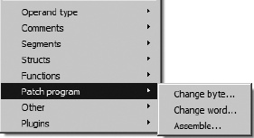
Each of the submenu items teases you with the notion that you are going to be able to modify the binary in potentially interesting ways. In actuality, what these options offer are three different ways to modify the database. In fact, these menu items, perhaps more than any others, make perfectly clear the distinction between an IDA database and the binary file from which the database was created. Once a database is created, IDA never references the original binary. Given its true behavior, this menu item would be more aptly named Patch Database.
All is not completely lost, however, as the menu options in Figure 14-1 do offer you the easiest way to observe the effect of any changes that you might eventually make to the original binary. Later in this chapter you will learn how to export the changes you have made and eventually use that information to patch the original binary.
The Edit ▸ Patch Program ▸ Change Byte menu option is used to edit one or more byte values within an IDA database. Figure 14-2 shows the related byte-editing dialog.
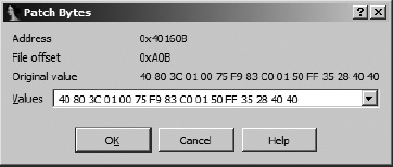
The dialog displays 16-byte values beginning at the current cursor location. You may change some or all of the displayed bytes, but you cannot make changes beyond the 16th byte without closing the dialog, repositioning the cursor to a new location farther into the database, and reopening the dialog. Note that the dialog displays the virtual address and the file offset value for the bytes that you are changing. This File offset value reflects the hexa-decimal offset at which the bytes reside within the original binary file. The fact that IDA retains the original file offset information for every byte in the database will be useful if you do wish to develop a patch for the original binary. Finally, regardless of the number of changes that have been made to the bytes in the database, the Original value field of the dialog always displays the original byte values loaded into the database. There is no automated capability for reverting changes to their original byte values, though it is possible to create an IDA script to perform such a task.
A better method for editing database bytes was introduced in IDA 5.5 in the form of a more capable Hex View window (see Chapter 5). With an integrated hex-editing capability, there is little need to use IDA’s change bytes capability.
Somewhat less useful than the byte-patching capability is IDA’s word-patching capability. Figure 14-3 shows IDA’s Patch Word dialog, which is capable of patching only one 2-byte word at a time.
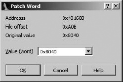
As with the byte-patching dialog, the virtual address and file offset are displayed. An important point to remember is that the word value is displayed using the natural byte ordering of the underlying processor. For example, in an x86 disassembly, words are treated as little-endian values, while in a MIPS disassembly, words are treated as big-endian values. Keep this in mind when entering new word values. As with the byte-patching dialog, the Original value field always displays the initial value loaded from the original binary file regardless of the number of times the word value may have been modified using the word-patching dialog. As with byte editing, it may be easier to perform your editing within IDA’s Hex View window.
Perhaps the most interesting capability accessible from the Patch Program menu is the Assemble option (Edit ▸ Patch Program ▸ Assemble). Unfortunately, this capability is not available for all processor types, as it relies on the presence of an internal assembler capability within the current processor module. For example, the x86 processor module is known to support assembly, while the MIPS processor module is known not to support assembly. When an assembler is not available, you will receive an error message stating, “Sorry, this processor module doesn’t support the assembler.”
The Assemble option allows you to enter assembly language statements that are assembled using an internal assembler. The resulting instruction bytes are then written to the current screen location. Figure 14-4 shows the Assemble Instruction dialog used for instruction entry.
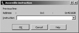
You can enter one instruction at a time into the Instruction field. The assembler component for IDA’s x86 processor module accepts the same syntax used in x86 disassembly listings. When you click OK (or press enter), your instruction is assembled, and the corresponding instruction bytes are entered into the database beginning at the virtual address displayed in the Address field. The internal IDA assembler allows you to use symbolic names within your instructions as long as those names exist within the program. Syntax such as mov [ebp+var_4], eax and call sub_401896 is perfectly legal, and the assembler will correctly resolve symbolic references.
Following entry of an instruction, the dialog remains open and ready to accept a new instruction at the virtual address immediately following the previously entered instruction. While you enter additional instructions, the dialog displays the previous instruction entered in the Previous line field.
When entering new instructions, you must pay attention to instruction alignment, especially when the instruction that you are entering is a different length than the instruction it is replacing. When a new instruction is shorter than the instruction it is replacing, you need to consider what to do with the excess bytes left over from the old instruction (inserting NOP[92] instructions is one possible option). When a new instruction is longer than the instruction that it is replacing, IDA will overwrite as many bytes of subsequent instructions as is required to fit the new instruction. This may or may not be the behavior you want, which is why careful planning is necessary before using the assembler to modify program bytes. One way to view the assembler is as a word processor that is stuck in overwrite mode. There is no easy way to open up space to insert new instructions without overwriting existing instructions.
It is important to remember that IDA’s database-patching capabilities are limited to small, simple patches that easily fit into existing space within the database. If you have a patch that requires substantial additional space, you will need to locate space that is allocated within the original binary but not used by the binary. Such space is often present in the form of padding, inserted by compilers to align sections of a binary to particular file boundaries. For example, in many Windows PE files, individual program sections must begin at file offsets that are multiples of 512 bytes. When a section does not consume an even multiple of 512 bytes of space, that section must be padded within the file in order to maintain a 512-byte boundary for the next section. The following lines from a disassembled PE file demonstrate this situation:
.text:0040963E ; [00000006 BYTES: COLLAPSED FUNCTION RtlUnwind. PRESS KEYPAD "+" TO EXPAND] .text:00409644align 200h .text:00409644 _text ends .text:00409644 .idata:0040A000 ; Section 2. (virtual address 0000A000)
In this case, IDA is using an align directive to indicate that the section is padded to a 512-byte (200h) boundary beginning from address .text:00409644. The upper end of the padding is the next multiple of 512 bytes, or .text:00409800. The padded area is generally filled with zeros by the compiler and stands out quite prominently in hex view. In this particular binary, there is space within the file to insert up to 444 (0x1BC = 409800h – 409644h) bytes of patched program data, which would overwrite some or all of the zero padding at the end of the .text section. You might patch a function to jump to this area of the binary, execute the newly inserted program instructions, and then jump back to the original function.
Note that the next section in the binary, the .idata section, does not actually begin until address .idata:0040A000. This is a result of a memory- (not file-) alignment restriction that requires PE sections to begin in 4Kb (one memory page) boundaries. In theory it should be possible to inject an additional 2,048 bytes of patched data into the memory range 00409800-0040A000. The difficulty in doing so lies in the fact that no bytes corresponding to this memory range are present within the disk image of the executable. In order to use this space, we would need to perform more than a simple overwrite of portions of the original binary file. First we would need to insert a 2,048-byte block of data between the end of the existing .text section and the beginning of the .idata section. Second, we would need to adjust the size of the .text section within the PE file headers. Finally, we’d need to adjust the location of .idata and all subsequent sections within the PE headers to reflect the fact that all following sections are now located 2,048 bytes deeper into the file. These changes may not sound terribly complicated, but they require some attention to detail and a good working knowledge of the PE file format.
[92] NOP stands for no operation and is an instruction often used simply to fill in space in a program.