Table of Contents for
The IDA Pro Book, 2nd Edition
 The IDA Pro Book, 2nd Edition
Published by
No Starch Press, 2011
The IDA Pro Book, 2nd Edition
Published by
No Starch Press, 2011
- Cover
- The IDA Pro Book
- PRAISE FOR THE FIRST EDITION OF THE IDA PRO BOOK
- Acknowledgments
- Introduction
- I. Introduction to IDA
- 1. Introduction to Disassembly
- The What of Disassembly
- The Why of Disassembly
- The How of Disassembly
- Summary
- 2. Reversing and Disassembly Tools
- Summary Tools
- Deep Inspection Tools
- Summary
- 3. IDA Pro Background
- Obtaining IDA Pro
- IDA Support Resources
- Your IDA Installation
- Thoughts on IDA’s User Interface
- Summary
- II. Basic IDA Usage
- 4. Getting Started with IDA
- IDA Database Files
- Introduction to the IDA Desktop
- Desktop Behavior During Initial Analysis
- IDA Desktop Tips and Tricks
- Reporting Bugs
- Summary
- 5. IDA Data Displays
- Secondary IDA Displays
- Tertiary IDA Displays
- Summary
- 6. Disassembly Navigation
- Stack Frames
- Searching the Database
- Summary
- 7. Disassembly Manipulation
- Commenting in IDA
- Basic Code Transformations
- Basic Data Transformations
- Summary
- 8. Datatypes and Data Structures
- Creating IDA Structures
- Using Structure Templates
- Importing New Structures
- Using Standard Structures
- IDA TIL Files
- C++ Reversing Primer
- Summary
- 9. Cross-References and Graphing
- IDA Graphing
- Summary
- 10. The Many Faces of IDA
- Using IDA’s Batch Mode
- Summary
- III. Advanced IDA Usage
- 11. Customizing IDA
- Additional IDA Configuration Options
- Summary
- 12. Library Recognition Using FLIRT Signatures
- Applying FLIRT Signatures
- Creating FLIRT Signature Files
- Summary
- 13. Extending IDA’s Knowledge
- Augmenting Predefined Comments with loadint
- Summary
- 14. Patching Binaries and Other IDA Limitations
- IDA Output Files and Patch Generation
- Summary
- IV. Extending IDA’s Capabilities
- 15. IDA Scripting
- The IDC Language
- Associating IDC Scripts with Hotkeys
- Useful IDC Functions
- IDC Scripting Examples
- IDAPython
- IDAPython Scripting Examples
- Summary
- 16. The IDA Software Development Kit
- The IDA Application Programming Interface
- Summary
- 17. The IDA Plug-in Architecture
- Building Your Plug-ins
- Installing Plug-ins
- Configuring Plug-ins
- Extending IDC
- Plug-in User Interface Options
- Scripted Plug-ins
- Summary
- 18. Binary Files and IDA Loader Modules
- Manually Loading a Windows PE File
- IDA Loader Modules
- Writing an IDA Loader Using the SDK
- Alternative Loader Strategies
- Writing a Scripted Loader
- Summary
- 19. IDA Processor Modules
- The Python Interpreter
- Writing a Processor Module Using the SDK
- Building Processor Modules
- Customizing Existing Processors
- Processor Module Architecture
- Scripting a Processor Module
- Summary
- V. Real-World Applications
- 20. Compiler Personalities
- RTTI Implementations
- Locating main
- Debug vs. Release Binaries
- Alternative Calling Conventions
- Summary
- 21. Obfuscated Code Analysis
- Anti–Dynamic Analysis Techniques
- Static De-obfuscation of Binaries Using IDA
- Virtual Machine-Based Obfuscation
- Summary
- 22. Vulnerability Analysis
- After-the-Fact Vulnerability Discovery with IDA
- IDA and the Exploit-Development Process
- Analyzing Shellcode
- Summary
- 23. Real-World IDA Plug-ins
- IDAPython
- collabREate
- ida-x86emu
- Class Informer
- MyNav
- IdaPdf
- Summary
- VI. The IDA Debugger
- 24. The IDA Debugger
- Basic Debugger Displays
- Process Control
- Automating Debugger Tasks
- Summary
- 25. Disassembler/Debugger Integration
- IDA Databases and the IDA Debugger
- Debugging Obfuscated Code
- IdaStealth
- Dealing with Exceptions
- Summary
- 26. Additional Debugger Features
- Debugging with Bochs
- Appcall
- Summary
- A. Using IDA Freeware 5.0
- Using IDA Freeware
- B. IDC/SDK Cross-Reference
- Index
- About the Author
As mentioned previously, IDA recognizes a tremendous number of data structures associated with various library and API functions. When a database is initially created, IDA attempts to determine the compiler and platform associated with the binary and loads the structure templates derived from related library header files. As IDA encounters actual structure manipulations in the disassembly, it adds the appropriate structure definitions to the Structures window. Thus, the Structures window represents the subset of known structures that happen to apply to the current binary. In addition to creating your own custom structures, you can add additional standard structures to the Structures window by drawing from IDA’s list of known structure types.
The process for adding a new structure begins by pressing the insert key inside the Structures window. Figure 8-3 showed the Create Structure/Union dialog, one component of which is the Add standard structure button. Clicking this button grants access to the master list of structures pertaining to the current compiler (as detected during the analysis phase) and file format. This master list of structures also contains any structures that have been added to the database as a result of parsing C header files. The structure selection dialog shown in Figure 8-13 is used to choose a structure to add to the Structures window.
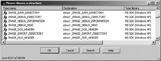
You may utilize the search functionality to locate structures based on a partial text match. The dialog also allows for prefix matching. If you know the first few characters of the structure name, simply type them in (they will appear in the status bar at the bottom of the dialog), and the list display will jump to the first structure with a matching prefix. Choosing a structure adds the structure and any nested structures to the Structures window.
As an example of using standard structures, consider a case in which you wish to examine the file headers associated with a Windows PE binary. By default, the file headers are not loaded into the database when it is first created; however, file headers can be loaded if you select the Manual load option during initial database creation. Loading the file headers ensures only that the data bytes associated with those headers will be present in the database. In most cases, the headers will not be formatted in any way because typical programs make no direct reference to their own file headers. Thus there is no reason for the analyzer to apply structure templates to the headers.
After conducting some research on the format of a PE binary, you will learn that a PE file begins with an MS-DOS header structure named IMAGE_DOS_HEADER. Further, data contained within the IMAGE_DOS_HEADER points to the location of an IMAGE_NT_HEADERS structure, which details the memory layout of the PE binary. Choosing to load the PE headers, you might see something similar to the following unformatted data disassembly. Readers familiar with the PE file structure may recognize the familiar MS-DOS magic value MZ as the first two bytes in the file.
HEADER:00400000 __ImageBase     db  4Dh ; M
HEADER:00400001                 db  5Ah ; Z
HEADER:00400002                 db  90h ; É
HEADER:00400003                 db    0
HEADER:00400004                 db    3
HEADER:00400005                 db    0
HEADER:00400006                 db    0
HEADER:00400007                 db    0
HEADER:00400008                 db    4
HEADER:00400009                 db    0
HEADER:0040000A                 db    0
HEADER:0040000B                 db    0
HEADER:0040000C                 db 0FFh
HEADER:0040000D                 db 0FFh
HEADER:0040000E                 db    0
HEADER:0040000F                 db    0
As this file is formatted here, you would need some PE file reference documentation to help you make sense of each of the data bytes. By using structure templates, IDA can format these bytes as an IMAGE_DOS_HEADER, making the data far more useful. The first step is to add the standard IMAGE_DOS_HEADER as detailed above (you could add the IMAGE_NT_HEADERS structure while you are at it). The second step is to convert the bytes beginning at __ImageBase into an IMAGE_DOS_HEADER structure using Edit ▸ Struct Var (alt-Q). This results in the reformatted display shown here:
HEADER:00400000 __ImageBase IMAGE_DOS_HEADER
 <5A4Dh, 90h, 3, 0, 4, 0, 0FFFFh, 0, 0B8h, \
HEADER:00400000                               0, 0, 0, 40h, 0, 0, 0, 0, 0, 80h>
HEADER:00400040 db 0Eh
As you can see, the first 64 (0x40) bytes in the file have been collapsed into a single data structure, with the type noted in the disassembly. Unless you possess encyclopedic knowledge of this particular structure, though, the meaning of each field may remain somewhat cryptic. We can take this operation one step further, however, by expanding the structure. When a structured data item is expanded, each field is annotated with its corresponding field name from the structure definition. Collapsed structures can be expanded using the plus key (+) on the numeric keypad. The final version of the listing follows:
HEADER:00400000 __ImageBase dw 5A4Dh ; e_magic HEADER:00400000 dw 90h ; e_cblp HEADER:00400000 dw 3 ; e_cp HEADER:00400000 dw 0 ; e_crlc HEADER:00400000 dw 4 ; e_cparhdr HEADER:00400000 dw 0 ; e_minalloc HEADER:00400000 dw 0FFFFh ; e_maxalloc HEADER:00400000 dw 0 ; e_ss HEADER:00400000 dw 0B8h ; e_sp HEADER:00400000 dw 0 ; e_csum HEADER:00400000 dw 0 ; e_ip HEADER:00400000 dw 0 ; e_cs HEADER:00400000 dw 40h ; e_lfarlc HEADER:00400000 dw 0 ; e_ovno HEADER:00400000 dw 4 dup(0) ; e_res HEADER:00400000 dw 0 ; e_oemid HEADER:00400000 dw 0 ; e_oeminfo HEADER:00400000 dw 0Ah dup(0) ; e_res2 HEADER:00400000dd 80h ; e_lfanew HEADER:00400040 db 0Eh
Unfortunately, the fields of IMAGE_DOS_HEADER do not possess particularly meaningful names, so we may need to consult a PE file reference to remind ourselves that the e_lfanew field indicates the file offset at which an IMAGE_NT_HEADERS structure can be found. Applying all of the previous steps to create an IMAGE_NT_HEADER at address 00400080 (0x80 bytes into the database) yields the nicely formatted structure shown in part here:
HEADER:00400080 dd 4550h ; Signature HEADER:00400080 dw 14Ch ; FileHeader.Machine HEADER:00400080dd 400000h ; OptionalHeader.ImageBase
Fortunately for us, the field names in this case are somewhat more meaningful. We quickly see that the file consists of five sections and should be loaded into memory at virtual address 00400000 . Expanded structures can be returned to their collapsed state using the minus key (−) on the keypad.