Table of Contents for
The IDA Pro Book, 2nd Edition
 The IDA Pro Book, 2nd Edition
Published by
No Starch Press, 2011
The IDA Pro Book, 2nd Edition
Published by
No Starch Press, 2011
- Cover
- The IDA Pro Book
- PRAISE FOR THE FIRST EDITION OF THE IDA PRO BOOK
- Acknowledgments
- Introduction
- I. Introduction to IDA
- 1. Introduction to Disassembly
- The What of Disassembly
- The Why of Disassembly
- The How of Disassembly
- Summary
- 2. Reversing and Disassembly Tools
- Summary Tools
- Deep Inspection Tools
- Summary
- 3. IDA Pro Background
- Obtaining IDA Pro
- IDA Support Resources
- Your IDA Installation
- Thoughts on IDA’s User Interface
- Summary
- II. Basic IDA Usage
- 4. Getting Started with IDA
- IDA Database Files
- Introduction to the IDA Desktop
- Desktop Behavior During Initial Analysis
- IDA Desktop Tips and Tricks
- Reporting Bugs
- Summary
- 5. IDA Data Displays
- Secondary IDA Displays
- Tertiary IDA Displays
- Summary
- 6. Disassembly Navigation
- Stack Frames
- Searching the Database
- Summary
- 7. Disassembly Manipulation
- Commenting in IDA
- Basic Code Transformations
- Basic Data Transformations
- Summary
- 8. Datatypes and Data Structures
- Creating IDA Structures
- Using Structure Templates
- Importing New Structures
- Using Standard Structures
- IDA TIL Files
- C++ Reversing Primer
- Summary
- 9. Cross-References and Graphing
- IDA Graphing
- Summary
- 10. The Many Faces of IDA
- Using IDA’s Batch Mode
- Summary
- III. Advanced IDA Usage
- 11. Customizing IDA
- Additional IDA Configuration Options
- Summary
- 12. Library Recognition Using FLIRT Signatures
- Applying FLIRT Signatures
- Creating FLIRT Signature Files
- Summary
- 13. Extending IDA’s Knowledge
- Augmenting Predefined Comments with loadint
- Summary
- 14. Patching Binaries and Other IDA Limitations
- IDA Output Files and Patch Generation
- Summary
- IV. Extending IDA’s Capabilities
- 15. IDA Scripting
- The IDC Language
- Associating IDC Scripts with Hotkeys
- Useful IDC Functions
- IDC Scripting Examples
- IDAPython
- IDAPython Scripting Examples
- Summary
- 16. The IDA Software Development Kit
- The IDA Application Programming Interface
- Summary
- 17. The IDA Plug-in Architecture
- Building Your Plug-ins
- Installing Plug-ins
- Configuring Plug-ins
- Extending IDC
- Plug-in User Interface Options
- Scripted Plug-ins
- Summary
- 18. Binary Files and IDA Loader Modules
- Manually Loading a Windows PE File
- IDA Loader Modules
- Writing an IDA Loader Using the SDK
- Alternative Loader Strategies
- Writing a Scripted Loader
- Summary
- 19. IDA Processor Modules
- The Python Interpreter
- Writing a Processor Module Using the SDK
- Building Processor Modules
- Customizing Existing Processors
- Processor Module Architecture
- Scripting a Processor Module
- Summary
- V. Real-World Applications
- 20. Compiler Personalities
- RTTI Implementations
- Locating main
- Debug vs. Release Binaries
- Alternative Calling Conventions
- Summary
- 21. Obfuscated Code Analysis
- Anti–Dynamic Analysis Techniques
- Static De-obfuscation of Binaries Using IDA
- Virtual Machine-Based Obfuscation
- Summary
- 22. Vulnerability Analysis
- After-the-Fact Vulnerability Discovery with IDA
- IDA and the Exploit-Development Process
- Analyzing Shellcode
- Summary
- 23. Real-World IDA Plug-ins
- IDAPython
- collabREate
- ida-x86emu
- Class Informer
- MyNav
- IdaPdf
- Summary
- VI. The IDA Debugger
- 24. The IDA Debugger
- Basic Debugger Displays
- Process Control
- Automating Debugger Tasks
- Summary
- 25. Disassembler/Debugger Integration
- IDA Databases and the IDA Debugger
- Debugging Obfuscated Code
- IdaStealth
- Dealing with Exceptions
- Summary
- 26. Additional Debugger Features
- Debugging with Bochs
- Appcall
- Summary
- A. Using IDA Freeware 5.0
- Using IDA Freeware
- B. IDC/SDK Cross-Reference
- Index
- About the Author
There are two ways to make use of structure definitions in your disassemblies. First, you can reformat memory references to make them more readable by converting numeric structure offsets such as [ebx+8] into symbolic references such as [ebx+ch8_struct.field4]. The latter form provides far more information about what is being referenced. Because IDA uses a hierarchical notation, it is clear exactly what type of structure, and exactly which field within that structure, is being accessed. This technique for applying structure templates is most often used when a structure is being referenced through a pointer. The second way to use structure templates is to provide additional datatypes that can be applied to stack and global variables.
In order to understand how structure definitions can be applied to instruction operands, it is helpful to view each definition as something similar to set of enumerated constants. For example, the definition of ch8_struct in Figure 8-5 might be expressed in pseudo-C as the following:
enum {
   ch8_struct.field1 = 0,
   ch8_struct.field2 = 4,
   ch8_struct.field3 = 6,
   ch8_struct.field4 = 8,
   ch8_struct.field5 = 16
};
Given such a definition, IDA allows you to reformat any constant value used in an operand into an equivalent symbolic representation. Figure 8-7 shows just such an operation in progress. The memory reference [ecx+10h] may represent an access to field5 within a ch8_struct.
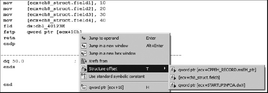
The Structure offset option, available by right-clicking 10h in this case, offers three alternatives for formatting the instruction operand. The alternatives are pulled from the set of structures containing a field whose offset is 16.
As an alternative to formatting individual memory references, stack and global variables can be formatted as entire structures. To format a stack variable as a structure, open the detailed stack frame view by double-clicking the variable to be formatted as a structure and then use Edit ▸ Struct Var (alt-Q) to display a list of known structures similar to that shown in Figure 8-8.

Selecting one of the available structures combines the corresponding number of bytes in the stack into the corresponding structure type and reformats all related memory references as structure references. The following code is an excerpt from the stack-allocated structure example we examined previously:
.text:00401006                 mov     [ebp+var_18], 10
.text:0040100D                 mov     [ebp+var_14], 20
.text:00401013                 mov     [ebp+var_12], 30
.text:00401017                 mov     [ebp+var_10], 40
.text:0040101E                 fld     ds:dbl_40B128
.text:00401024                 fstp    [ebp+var_8]
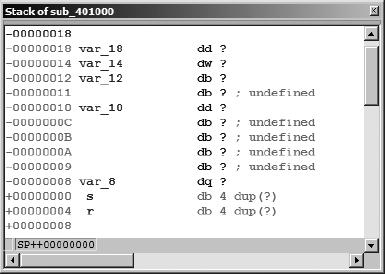
Recall that we concluded that var_18 is actually the first field in a 24-byte structure. The detailed stack frame for this particular interpretation is shown in Figure 8-9.
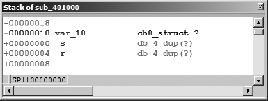
Selecting var_18 and formatting it as a ch8_struct (Edit ▸ Struct Var) collapses the 24 bytes (the size of ch8_struct) beginning at var_18 into a single variable, resulting in the reformatted stack display shown in Figure 8-10. In this case, applying the structure template to var_18 will generate a warning message indicating that some variables will be destroyed in the process of converting var_18 into a structure. Based on our earlier analysis, this is to be expected, so we simply acknowledge the warning to complete the operation.
Following reformatting, IDA understands that any memory reference into the 24-byte block allocated to var_18 must refer to a field within the structure. When IDA encounters such a reference, it makes every effort to resolve the memory reference to one of the defined fields within the structure variable. In this case, the disassembly is automatically reformatted to incorporate the structure layout, as shown here:
.text:00401006                 mov     [ebp+var_18.field1], 10
.text:0040100D                 mov     [ebp+var_18.field2], 20
.text:00401013                 mov     [ebp+var_18.field3], 30
.text:00401017                 mov     [ebp+var_18.field4], 40
.text:0040101E                 fld     ds:dbl_40B128
.text:00401024                 fstp    [ebp+var_18.field5]
The advantage to using structure notation within the disassembly is an overall improvement in the readability of the disassembly. The use of field names in the reformatted display provides a much more accurate reflection of how data was actually manipulated in the original source code.
The procedure for formatting global variables as structures is nearly identical to that used for stack variables. To do so, select the variable or address that marks the beginning of the structure and use Edit ▸ Struct Var (alt-Q) to choose the appropriate structure type. As an alternative for undefined global data only (not stack data), you may use IDA’s context-sensitive menu, and select the structure option to view and select an available structure template to apply at the selected address.