Table of Contents for
Linux Essentials for Cybersecurity, First Edition
 Linux Essentials for Cybersecurity, First Edition
Published by
Pearson IT Certification, 2018
Linux Essentials for Cybersecurity, First Edition
Published by
Pearson IT Certification, 2018
- Cover Page
- Title Page
- Copyright Page
- Contents at a Glance
- Table of Contents
- About the Author
- Dedication
- Acknowledgments
- About the Technical Reviewers
- We Want to Hear from You!
- Reader Services
- Introduction
- Part I: Introducing Linux
- Chapter 1: Distributions and Key Components
- Chapter 2: Working on the Command Line
- Chapter 3: Getting Help
- Chapter 4: Editing Files
- Chapter 5: When Things Go Wrong
- Part II: User and Group Accounts
- Chapter 6: Managing Group Accounts
- Chapter 7: Managing User Accounts
- Chapter 8: Develop an Account Security Policy
- Part III: File and Data Storage
- Chapter 9: File Permissions
- Chapter 10: Manage Local Storage: Essentials
- Chapter 11: Manage Local Storage: Advanced Features
- Chapter 12: Manage Network Storage
- Chapter 13: Develop a Storage Security Policy
- Part IV: Automation
- Chapter 14: Crontab and At
- Chapter 15: Scripting
- Chapter 16: Common Automation Tasks
- Chapter 17: Develop an Automation Security Policy
- Part V: Networking
- Chapter 18: Networking Basics
- Chapter 19: Network Configuration
- Chapter 20: Network Service Configuration: Essential Services
- Chapter 21: Network Service Configuration: Web Services
- Chapter 22: Connecting to Remote Systems
- Chapter 23: Develop a Network Security Policy
- Part VI: Process and Log Administration
- Chapter 24: Process Control
- Chapter 25: System Logging
- Part VII: Software Management
- Chapter 26: Red Hat–Based Software Management
- Chapter 27: Debian-Based Software Management
- Chapter 28: System Booting
- Chapter 29: Develop a Software Management Security Policy
- Part VIII: Security Tasks
- Chapter 30: Footprinting
- Chapter 31: Firewalls
- Chapter 32: Intrusion Detection
- Chapter 33: Additional Security Tasks
- Appendix A: Answers to Review Questions
- Appendix B: Resource Guide
- Glossary
Chapter 18 Networking Basics
In order to correctly configure your network, be able to troubleshoot network issues, and properly secure network connections, you need to understand some basic principles of networking first. The goal of this chapter is to cover these principles.
We start by discussing some essential network terms, including hosts, IP addresses, and protocols. Also included in this chapter is a discussion on subnetting and network ports.
It is important to keep in mind that this chapter focuses on the essentials of networking. Networking is a very large topic, and entire books are devoted to the principles and features of modern networking environments. We encourage you to learn more about networking than what is provided in this chapter, but in terms of the goal of learning Linux and configuring a Linux network, the content in this chapter provides you with the foundation you need.
After reading this chapter and completing the exercises, you will be able to do the following:
Explain essential network terminology.
Define network addresses, including subnetting.
Describe common network ports.
Identify the primary differences between IPv4 and IPv6.
Describe common network protocols.
Network Terminology
A network is created when two or more computers communicate through some sort of connection. This connection could be created via several different technologies, including Ethernet, fiber optic, and wireless.
Each computer on the network is called a host, and it can include a large number of different systems, such as desktop and laptop computers, printers, routers, switches, and even cell phones. Although the focus in this chapter is on computers that have a Linux operating system, you should consider any system that communicates on the network as a host.
There are two general classes of networks:
• LAN (local area network): This network describes all the hosts that communicate directly with one another on the same network.
• WAN (wide area network): This network describes a collection of LANs that are able to communicate through a series of routers or switches. Routers and switches have the ability to transfer network communications from one network to another.
Figure 18-1 provides an example that illustrates a LAN versus a WAN.
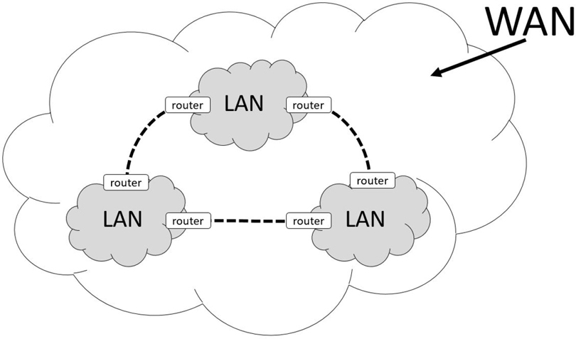
Figure 18-1 LAN and WAN
Data is sent across networks using a network packet. A network packet is a well-defined message that includes the data as well as metadata (called the packet header). The packet header provides information about how the network packet is to reach its destination. You can think of a network packet like a letter you would send in the mail. The letter in the envelope is the data, and the address information written on the envelope is the packet header. In reality, the packet header will contain much more information than appears on the envelope of a letter that you mail, but the analogy is apropos.
Included in the packet header are two pieces of information that help determine the destination of the packet: the IP (Internet Protocol) address of the destination host and the port of the destination host. An IP address is a unique numeric-based value that is like the street name on a traditional envelope. For example, suppose you sent a letter as shown in Figure 18-2.
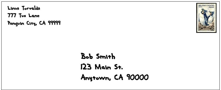
Figure 18-2 Traditional Mailing Address
You can consider the IP address to be “123 Main St.”, which means you can think of that one house as analogous to a host. The port is a numeric value that is associated to a service, which is a program that is running on the host that is listening for incoming messages on a specific port number. For example, you could have a web server installed on a host that will listen to incoming network packets destined for port 80. Going back to our traditional mail message analogy, you can consider a port number to be like the person’s name identifying to whom the envelop is addressed (Bob Smith in the previous example).
Recall that a WAN is a collection of LANs that can communicate with each other through routers or switches. The way that a router or switch determines which LAN to send a message to is via a subnet value. The subnet value, when combined with the IP address, creates a unique network address. How this happens is covered later in this chapter. You can think of the subnet value for a traditional mail message like the city, state, and ZIP code of a letter, which allows mail carriers to route the envelope to the correct geographic location. In a sense, you could also consider each city to be analogous to a LAN and the entire country (or world even) to be analogous to a WAN.
Within the network packet resides the data. The data must be formatted in a way that the receiving system understands. This is partly handled by protocols. A protocol is a well-defined standard for network communications between two hosts. For example, web servers often use HTTP (Hypertext Transfer Protocol) as the means of communication between the client host and the server. A server is a host on a network that offers a service; it serves something to the receiver, which is known as a client. That is why when you use a web browser, you typically type a web address like this: http://www.OneCourseSource.com.
A server may understand multiple protocols. For example, web servers also understand FTP (File Transfer Protocol) and HTTPS (HTTP Secure).
Protocols are used at a higher level of networking to define networking operations. For example, recall that each host on a network has a unique IP address (Internet Protocol address). This protocol is used to determine where to send information across a network. Other common network protocols include TCP (Transmission Control Protocol), UDP (User Datagram Protocol), and ICMP (Internet Control Message Protocol). Critical details regarding these protocols are provided later in this chapter.
Note
There are literally hundreds of standard protocols, and in most cases you do not have to worry about the details of the protocols. However, if you want to learn more about a protocol than what is provided in this book, then visit one of the many sites that describe RFCs (requests for comments), such as https://www.rfc-editor.org.
IPv4 Versus IPv6
The two different versions of IP are IPv4 and IPv6. IPv4 has been a standard on the Internet for a very long time and is slowly being replaced by IPv6. There are many differences between these two versions, but a complete discussion is beyond the scope of this book. Instead, we will consider one of the major differences and then provide a chart that illustrates some of the other differences.
To understand this major difference, first consider this: there are 4,294,967,296 total possible unique IPv4 addresses. That may seem like a lot, and perhaps even more than we could possibly need, but the way in which these IP addresses are categorized and distributed resulted in a shortage of available IP addresses that was first recognized in the 1990s. Every device that is connected to the Internet needs a unique identifier so that communication with the device works properly We will go more into this in a later section on how IPv4 addresses work, but for now realize that there was a time when we had a valid concern that we would run out of IPv4 addresses.
IPv4 uses a technique called dotted decimal notation (also known as dot delimited), a 32-bit number divided into four octets that results in about 4.3 possible IP addresses. IPv6 uses a different technique called hexadecimal notation, a 128-bit number. This technique results in 340,282,366,920,938,463,463,374,607,431,768,211,456 IPv6 addresses (if this number is too big to comprehend, think “340 trillion, trillion, trillion” or “many trillion addresses available for each person alive today”). In other words, we have plenty of IP addresses for all the hosts on the Internet now and the foreseeable future.
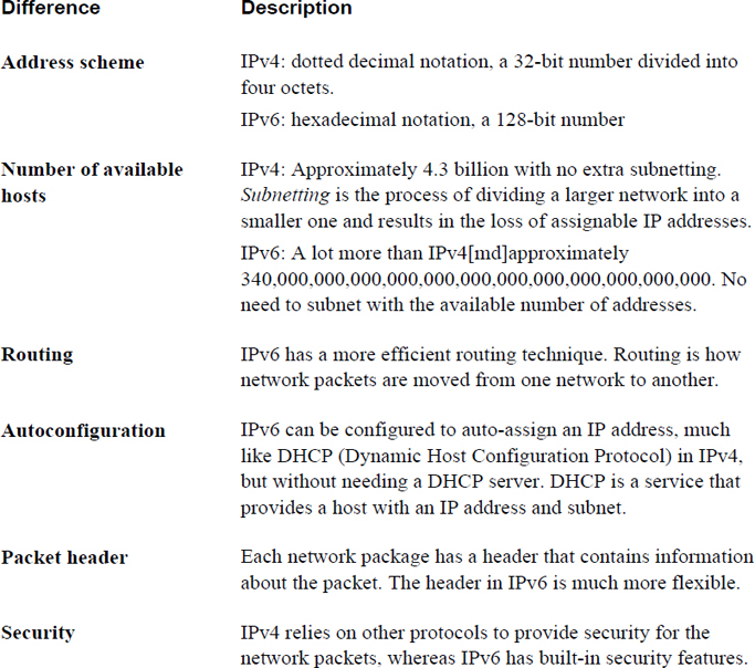
IPv6 has other advantages over IPv4, as described in Table 18-1.
Table 18-1 Some Differences Between IPv4 and IPv6
Security Highlight
IPv6 is generally considered more secure, but keep in mind that if you use IPv6 on systems connected to the Internet, at some point the network packets are likely to be converted into IPv4 packets (usually soon after leaving your network). As a result, the security features offered by IPv6 are typically only useful within your own organization.
Note that Table 18-1 is not a complete description of the differences between IPv6 and IPv4, but it should provide you with the general idea that IPv6 is a better overall protocol. This might lead you wonder why it is “slowly” replacing IPv4—and, by the way, we do mean slowly. IPv6 was introduced in January of 1996, and by its 20th birthday it was only enabled on about 10% of the world’s computers. More recent estimates have this number approaching 25%.
There are many reasons why the Internet has not switched completely to IPv6, but here are two of the most common reasons:
• Switching an entire network from IPv4 to IPv6 is not a trivial task. The protocols are vastly different in many ways, so a lot of care and work must take place to make this switch happen smoothly and transparently. And even if your organization did switch to IPv6, at some point to connect to the rest of the Internet, network communication must be converted into IPv4 because most of the Internet is still using IPv4.
• Recall the concern about running out of IPv4 addresses? That concern was just about eliminated by the invention of an IPv4 feature called NAT (Network Address Translation). With NAT, a single host (in this case, a router) can have one IPv4 address that can communicate directly on the network. The LAN that the router is connected to uses a set of IP addresses (called private IP addresses) that cannot be used directly on the Internet. The router translates all incoming and outgoing network packets between the Internet and the internal private network, allowing the hosts in the internal private network indirect access to the Internet though the NAT router. Almost all hosts today, including your cell phone and devices within your home (like many flat screen televisions, and even refrigerators), have internal private IP addresses. With the wide spread adoption of NAT, the concern about running out of IPv4 address is eliminated because only a small number of routers with live IP addresses are required to allow hundreds of hosts indirect access to the Internet.
Because IPv4 is still the dominate protocol used on the Internet, this book will focus on IPv4 rather than IPv6. However, you should know the differences between the two, as described in this chapter, and you should consider learning more about IPv6 for the future.
IPv4 Addresses
An IPv4 address consists of four numbers separated by a dot character (for example, 192.168.100.25). Each number reprints an octet, a number that can be represented by a binary value, like so:
11000000.10101000.01100100.00011001
192 can be represented by the binary number 11000000 because each binary value represents a numeric value, as shown in Figure 18-3.
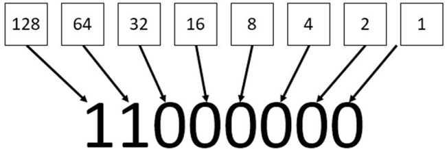
Figure 18-3 Binary Representation of Numeric Values
IPv4 addresses are divided into classes, and there are five classes total. These classes are defined by the first octet (the first number of the IP address). For example, the IP address of 192.168.100.25 uses the 192 value to define in which of the five primary classes the IP resides. Table 18-2 describes these standard IPv4 address classes.
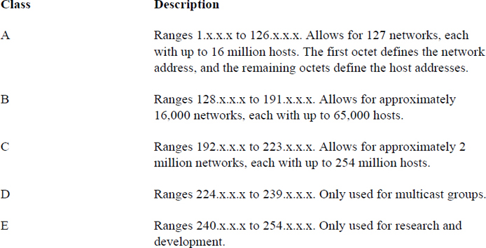
So, a Class A network of 55.x.x.x can have up to 16 million host IP addresses that run from 55.0.0.1 (55.0.0.0 is reserved for the network itself) to 55.254.254.254 (technically the highest value is 255, but those IP addresses are reserved for broadcasting messages to the entire network).
Organizations that have been assigned large networks (Class A or B, although even Class C networks apply here) do not want to have millions or even thousands of hosts on a single network. Subnetting provides a method of dividing a large network into smaller sections. This is accomplished by making smaller networks (subnetworks) by using IP addresses that are normally used by hosts to define the network and broadcast IP addresses.
There are two common network situations in which you should know how subnets work:
• When a system already has an IP address and a subnet address, you want to know how to determine the subnetwork that is created.
• When you have a larger IP network and want to know how to divide it into smaller networks. This is important if you have several smaller physical networks in your organization because each physical network must be on a separate subnetwork.
In both of these situations, you can use on of the many IP address calculators freely available on the Internet to aid you in the process. The purpose of showing you how to perform these tasks by hand is to aid you in understanding how subnetting works.
Determining a Network Address from an IP Address and Subnet
Suppose you were using a full Class C network of 192.168.100.0. This means that the first three octets (192.168.100.0) are used for the network address, the last possible IP address is the broadcast address (192.168.100.255), and all other IP addresses (192.168.100.1 to 192.168.1.254) can be assigned to hosts on the network.
Perhaps having 254 hosts in a single physical network does not work for your situation and you want to divide this class C network into smaller networks. Before doing this, consider how the network is defined in the first place by looking at Table 18-3.
Table 18-3 Class C Network Definition
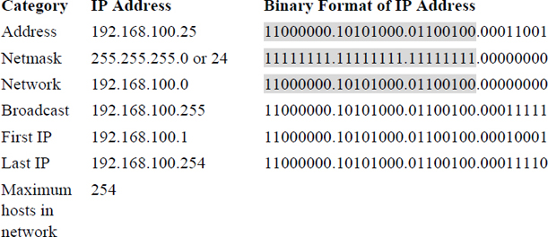
In Table 18-3, the IP address is displayed in both dotted decimal notation (192.168.100.25) and binary format. The subnet mask is displayed in three formats:
• Variable-Length Subnet Mask (VLSM) format: Essentially the same format as dotted decimal notation.
• Classless Inter-Domain Routing (CIDR) format: This is the same value as VLSM, but described in a different way. This value is the number of “1” values in the binary format (add them up and you will get 24 “1” values for the netmask in Table 18-3).
• Binary format: As shown in Table 18-3.
To determine which part of the IP address represents the network, just look at all the bits in the binary format that are a value of “1” for both the IP address and the subnet mask. To make this easier to see, this has been highlighted in grey in Table 18-3.
The first possible address in this network defines the network itself (192.168.100.0 in Table 18-3) and the last possible address in this network defines the broadcast address (192.168.100.255 in Table 18-3).
The example in Table 18-3 is straightforward because it is one of the standard classes. Look at the example in Table 18-4 and see how a different, nonstandard subnet (255.255.255.240) would affect the various IP addresses.
Table 18-4 Nonstandard Subnet Mask Example

Note
It may take some time to understand the process of subnetting. We highly encourage you to practice by using one of the many subnet calculators freely available on the Internet, such as the one found at the following address: https://www.adminsub.net/ipv4-subnet-calculator.
Private IP Addresses
As previously mentioned, private IP addresses are used with routers that utilize NAT. One network per Internet class (A, B and C) has been set aside for private IP addresses. Any host with an IP address in one of these ranges must connect to the Internet via a router that utilizes NAT.
Most organizations use private IP addresses for most hosts, using public IP for systems like firewalls, web servers, and other hosts that need to be directly available on the Internet. As a result, you should be familiar with the ranges of IP addresses that are for private use only:
• 10.0.0.0-10.255.255.255
• 172.16.0.0-172.31.255.255
• 192.168.0.0-192.168.255.255
Common Protocol Suites
You should be familiar with the following protocol suites:
• IP (Internet Protocol): This protocol is responsible for delivering network packets between hosts. Its functions include routing, or sending packets from one physical network to another. Often network packets are forwarded through several routers before reaching the correct destination.
• TCP (Transmission Control Protocol): This protocol compliments IP (Internet Protocol), which is why you will commonly hear the term TCP/IP. TCP is designed to ensure that the network packages arrive in a reliable and ordered manner. With TCP, data packages are connection based, which means error checking is performed to determine if packages are lost in transmission. If a packet is lost, a replacement packet is created and sent. TCP is generally slower than UDP (see definition of UDP) because error-checking each package requires more “work.” Also, the loss of a package requires a request to resend the packages, which can have an impact on subsequent packages. However, it is more reliable than UDP because all packages are verified. One example of the use of TCP is the downloading of a software program.
• UDP (User Datagram Protocol): Like TCP, this protocol complements IP (Internet Protocol). It performs a similar function to TCP; however, data packages are connectionless, which means no error checking is performed to determine if packages are lost in transmission. As a result, it is faster than TCP because connectionless data transfer requires less “work.” It is also less reliable than TCP because of the lack of error checking. One example of the use of UDP is live streaming of video, in which the loss of an occasional packet does not have any major impact on the overall data flow.
• ICMP (Internet Control Message Protocol): This protocol is used primarily to send error messages and for determining the status of network devices. It is unlike TCP or UDP in that it is designed to send simple messages, not transfer data between devices or establish connections between devices. One example of the use of ICMP is the ping command (see Chapter 19, “Network Configuration”), which is used to verify that a host can be contacted via the network.
Network Ports
The /etc/services file is the traditional location where services are mapped to ports. It is considered traditional in the sense that historically services would look at this file to determine which port the service should use. However, most modern services have a setting in the configuration file that is used to determine the actual port that the service will use.
The /etc/services file is still useful to administrators in that it contains ports that have been assigned to services by the Internet Assigned Numbers Authority (IANA).
Each line in this file describes one service-to-port mapping. The format of the line is as follows:
service_name port/protocol [alias]
For example:
[root@localhost ~]# grep smtp /etc/services
smtp            25/tcp          mail
smtp            25/udp          mail
rsmtp           2390/tcp                # RSMTP
rsmtp           2390/udp                # RSMTP
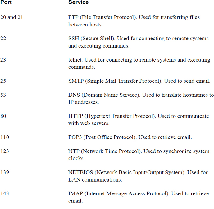
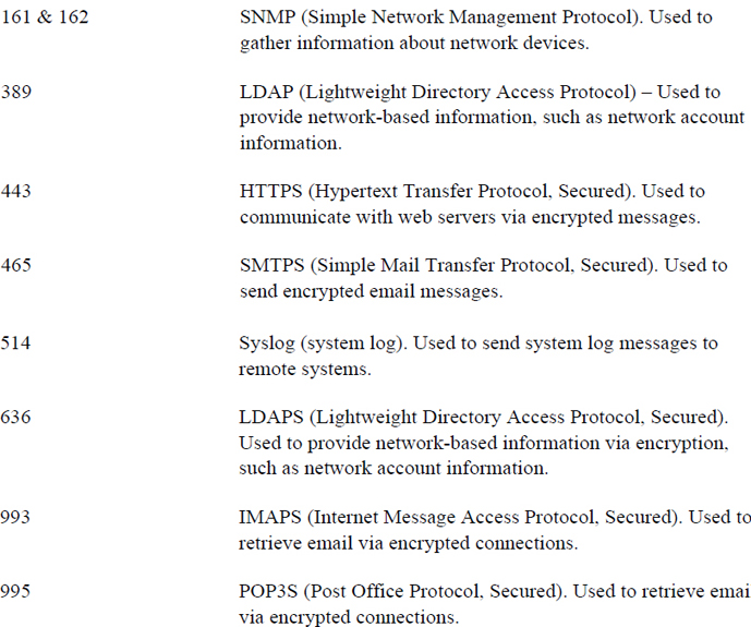
Table 18-5 lists the usage for common ports and services. Note that the descriptions are intentionally short, and much more detail is necessary to fully understand each protocol. However, understanding generally the protocol’s function is the primary goal here. For many of these protocols, you will be introduced to the software services that use the protocols in Chapter 19, “Network Configuration.”
Table 18-5 Common Network Ports
Conversational Learning™ — Making Sense of Protocols
Gary: Hey, Julia.
Julia: Gary, you seem down. What’s going on?
Gary: I’m just trying to get my head around all of these protocols. I’ve just begun to understand what a protocol is, and now I found out there are so many that do a lot of different things.
Julia: I understand. Even experienced administrators can find the large number of protocols overwhelming. Maybe I can provide you with some advice?
Gary: Anything would help!
Julia: First, understand that you don’t have to know everything about every protocol. Each system or host will only have a handful of services, perhaps even just one that it provides to the network. For example, a server that provides network accounts via LDAP isn’t likely to also be a web server and a mail server.
Gary: OK, so I should focus on the services that are provided by the hosts that I am going to maintain, right?
Julia: That is a great place to start. Also realize that understanding the details of the protocol isn’t normally so important. Knowing how to configure the service to use the protocol and how to implement key security features is what is really important.
Gary: Ah, that makes me feel a bit better! I tried to read through one of those RFCs and my head started spinning.
Julia: Trust me, you aren’t the only one who has experienced that!
Summary
In this chapter, you explored several key networking concepts. The goal of this chapter was not to make you a networking expert, but to introduce you to these concepts to make the process of configuring, maintaining, troubleshooting, and securing a network easier.
Key Terms
Review Questions
1. A _____ is a well-defined standard for network communications between two hosts.
2. Which is true about TCP?
a. It is connectionless.
b. It is generally faster than UDP.
c. It ensures data arrives in a reliable manner.
d. It does not perform error checking.
3. Which protocol is designed for determining the status of network devices?
a. FTP
b. POP3
c. telnet
d. ICMP
4. The /etc/_____ file contains traditional service-to-port mappings.
5. The _____ protocol is used to translate hostnames to IP addresses.