Table of Contents for
Packet Tracer Network Simulator
 Packet Tracer Network Simulator
Published by
Packt Publishing, 2014
Packet Tracer Network Simulator
Published by
Packt Publishing, 2014
- Cover
- Table of Contents
- Packet Tracer Network Simulator
- Packet Tracer Network Simulator
- Credits
- About the Author
- About the Reviewers
- www.PacktPub.com
- Preface
- Who this book is for
- Conventions
- Reader feedback
- Customer support
- 1. Getting Started with Packet Tracer
- Installing Packet Tracer
- Interface overview
- Creating a simple topology
- Summary
- 2. Network Devices
- Customizing devices with modules
- Emulating WAN
- Accessing the CLI
- Summary
- 3. Generic IP End Devices
- Servers
- Other end devices
- Configuring end devices
- Summary
- 4. Creating a Network Topology
- Testing connectivity with PDUs
- Using the simulation mode
- Clustering a topology
- Summary
- 5. Navigating and Modifying the Physical Workspace
- Moving devices physically
- Managing cables and distances
- Customizing icons and backgrounds
- Summary
- 6. Configuring Routing with the CLI
- Dynamic routing protocols
- The Routing table
- Load sharing
- Summary
- 7. Border Gateway Protocol (BGP)
- BGP versus dynamic routing protocols
- Configuring BGP in Packet Tracer
- Summary
- 8. IPv6 on Packet Tracer
- IPv6 static and dynamic routing
- Using both IPv4 and IPv6
- Summary
- 9. Setting Up a Wireless Network
- Wireless networks and physical workspaces
- Summary
- 10. Configuring VLANs and Trunks
- InterVLAN routing with routers and layer 3 switches
- Switch-to-switch trunk links
- Analyzing broadcasts in the simulation mode
- Summary
- 11. Creating Packet Tracer Assessments
- The initial network
- The answer network
- Testing the activity
- Summary
- Index
Although VLAN is used to split the broadcast domain, it is necessary to enable communication between two or more VLANs at layer 3 using IP routing. This is called InterVLAN routing and can be configured using both routers and layer 3 switches. This requires allocating a different IP subnet for devices in each VLAN.
We will configure InterVLAN routing by connecting the router to a switch using a single link. All the traffic to other VLANs passes through this link, to the router and back again through this link. This method of configuration is also called router-on-a-stick, as a single link to the router handles all traffic.
We will use the following topology for this setup:
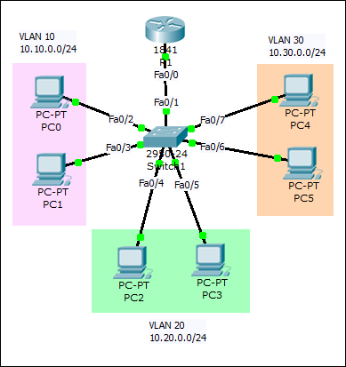
As stated earlier, each VLAN will have IP addresses from different network ranges and the router's interface will have three IP addresses—each belonging to a different network.
- After IP addresses have been assigned to all PCs, create the necessary VLANs on the switch and assign the ports to them.
Sw1(config)#int range f0/2-3
Sw1(config-if-range)#switchport access vlan 10
Sw1(config-if-range)#int range f0/4-5
Sw1(config-if-range)#switchport access vlan 20
Sw1(config-if-range)#int range f0/6-7
Sw1(config-if-range)#switchport access vlan 30
- Configure the switch port that connects to the router as a trunk link. More on this in the Switch-to-switch trunk links section.
Sw1(config)#int f0/1
Sw1(config-if)#switchport mode trunk
- Now, moving on to the router portion of the configuration, bring the interface up.
R1(config)#int f0/0
R1(config-if)#no shutdown
- We will now create the subinterfaces. Each will have its own IP address in a different network.
R1(config-subif)#int f0/0.10
R1(config-subif)#encapsulation dot1Q 10
R1(config-subif)#ip address 10.10.0.1 255.255.255.0
R1(config-subif)#int f0/0.20
R1(config-subif)#encapsulation dot1Q 20
R1(config-subif)#ip address 10.20.0.1 255.255.255.0
R1(config-subif)#int f0/0.30
R1(config-subif)#encapsulation dot1Q 30
R1(config-subif)#ip address 10.30.0.1 255.255.255.0
- Notice the
encapsulationcommand here. It specifies the VLAN ID the interface will handle. - That's it, now test the connectivity between hosts on different VLANs using simple PDUs or a ping. The first packet will always time out as it takes some time for the ARP (Address Resolution Protocol) to complete.
The only layer 3 switch present on Packet Tracer is 3560-24PS. We will use the same topology by replacing only the router with the layer 3 switch, as shown in the following screenshot:
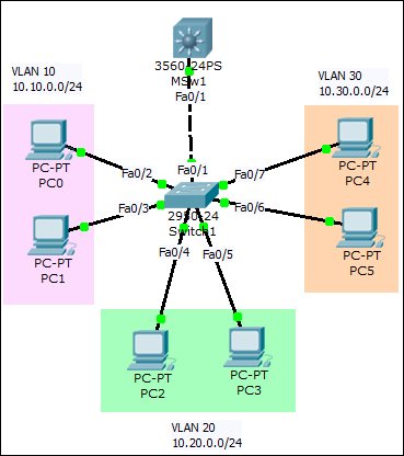
Creation and configuration of VLANs is the same on the layer 2 switch, hence it won't be repeated here. So, we'll move to the layer 3 switch straightaway.
- Since the switch-switch link on the layer 2 switch was set to trunking mode with the
switchport mode trunkcommand, the same port on the layer 3 switch will also be in trunking mode. This can be verified as follows:MSw1#sh interface trunk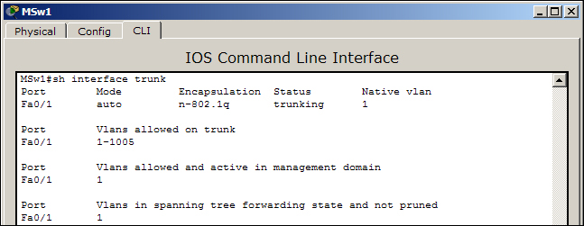
The
trunkingstatus indicates this. More on how this port automatically moved to trunk will be discussed in the next section (Switch-to-switch trunk links). - We will configure what is called SVI (Switch Virtual Interface), which will act as layer 3 interfaces for each VLAN.
MSw1(config)#int vlan 10
MSw1(config-if)#ip add 10.10.0.1 255.255.255.0
MSw1(config-if)#int vlan 20
MSw1(config-if)#ip add 10.20.0.1 255.255.255.0
MSw1(config-if)#int vlan 30
MSw1(config-if)#ip add 10.30.0.1 255.255.255.0
- These interfaces will stay down, as this layer 3 switch doesn't have VLANs
10,20, and30. So we'll create them as follows:MSw1(config)#vlan 10 MSw1(config-vlan)#vlan 20 MSw1(config-vlan)#vlan 30
- As each command is entered, the associated SVI will come up. IP Routing has to be enabled.
MSw1(config)#ip routing - Use the simple PDU tool to test the connectivity.
Here, too, the first packet will always time out as the ARP process takes some time.