Table of Contents for
Packet Tracer Network Simulator
 Packet Tracer Network Simulator
Published by
Packt Publishing, 2014
Packet Tracer Network Simulator
Published by
Packt Publishing, 2014
- Cover
- Table of Contents
- Packet Tracer Network Simulator
- Packet Tracer Network Simulator
- Credits
- About the Author
- About the Reviewers
- www.PacktPub.com
- Preface
- Who this book is for
- Conventions
- Reader feedback
- Customer support
- 1. Getting Started with Packet Tracer
- Installing Packet Tracer
- Interface overview
- Creating a simple topology
- Summary
- 2. Network Devices
- Customizing devices with modules
- Emulating WAN
- Accessing the CLI
- Summary
- 3. Generic IP End Devices
- Servers
- Other end devices
- Configuring end devices
- Summary
- 4. Creating a Network Topology
- Testing connectivity with PDUs
- Using the simulation mode
- Clustering a topology
- Summary
- 5. Navigating and Modifying the Physical Workspace
- Moving devices physically
- Managing cables and distances
- Customizing icons and backgrounds
- Summary
- 6. Configuring Routing with the CLI
- Dynamic routing protocols
- The Routing table
- Load sharing
- Summary
- 7. Border Gateway Protocol (BGP)
- BGP versus dynamic routing protocols
- Configuring BGP in Packet Tracer
- Summary
- 8. IPv6 on Packet Tracer
- IPv6 static and dynamic routing
- Using both IPv4 and IPv6
- Summary
- 9. Setting Up a Wireless Network
- Wireless networks and physical workspaces
- Summary
- 10. Configuring VLANs and Trunks
- InterVLAN routing with routers and layer 3 switches
- Switch-to-switch trunk links
- Analyzing broadcasts in the simulation mode
- Summary
- 11. Creating Packet Tracer Assessments
- The initial network
- The answer network
- Testing the activity
- Summary
- Index
First, let's look at the commands used in BGP:
router bgp <asn>
For example:
R1(config)#router bgp 120
This command enables BGP on a router and moves to the router configuration mode. The ASN can be any value between 1 and 65535. Once enabled, the BGP process must choose a router ID. By default, BGP uses the following methods priority-wise, to pick a router ID.
- Configured: This is the router ID configured by using the
bgp router-idrouter subcommand - Highest loopback: This is the highest numeric IP address configured on any up loopback interface at the time the BGP process is initialized
- Highest other interfaces: This is the highest numeric IP address configured on any up non-loopback interface at the time the BGP process is initialized
A router ID can be explicitly configured using the following command:
bgp router-id X.X.X.X
For example, we can use the following command to configure the router ID:
R1(config-router)#bgp router-id 1.1.1.1
For configuring a BGP neighbor, we can use the following command:
R1(config-router)#neighbor X.X.X.X remote-as <asn>
For example:
R1(config-router)#neighbor 10.0.0.2 remote-as 130
The ASN entered for remote-as should be the ASN of the neighboring router. This changes in eBGP and is the same in iBGP. Let us look at an example.
The following commands are used to change the eBGP:
R1(config)#router bgp 120
R1(config-router)#neighbor 10.0.0.2 remote-as 130
The following commands are used to change the iBGP:
R1(config)#router bgp 120
R1(config-router)#neighbor 192.168.1.20 remote-as 120
As mentioned earlier, when exchanging routes within an AS, iBGP doesn't modify the next-hop field. This can become problematic because the next hop is the IP of the neighboring AS's router, and unless it is redistributed by using an IGP, the internal network will reject the routes because the next hop is invalid. So, the following command sets its own IP as the next-hop of a route:
R1(config-router)#neighbor X.X.X.X next-hop-self
BGP also has a network command. This is used to specify a route that will be advertised in BGP. This route should exist in the routing table to be advertised in BGP:
R1(config-router)#network 10.20.20.0 mask 255.255.255.0
It is also possible to omit the mask command, doing which it takes the network as a classful one.
There are a lot of other commands in BGP that Packet Tracer doesn't support, so we'll go ahead and configure a topology using these commands.
For this exercise, we'll use a single mutihomed design (shown in the following screenshot) as Packet Tracer doesn't support iBGP:
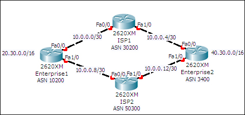
This topology has four routers—two belonging to different enterprises and the other two belonging to different ISPs. Both the enterprise routers have loopback interfaces configured with the IP addresses shown in the topology. This is to demonstrate the injecting of routes into BGP.
The following table lists the interfaces and their IP addresses:
|
Device |
Interface |
IP address / Subnet Mask |
|---|---|---|
|
Enterprise1 |
Loopback0 |
|
|
FastEthernet0/0 |
| |
|
FastEthernet1/0 |
| |
|
Enterprise2 |
Loopback0 |
|
|
FastEthernet0/0 |
| |
|
FastEthernet1/0 |
| |
|
ISP1 |
FastEthernet0/0 |
|
|
FastEthernet1/0 |
| |
|
ISP2 |
FastEthernet0/0 |
|
|
FastEthernet1/0 |
|
The following are the steps to configure BGP on the meshed network topology:
- Let's start configuring BGP on the enterprise routers:
Enterprise1(config)#router bgp 10200
Enterprise1(config-router)# bgp router-id 0.0.0.1
Enterprise1(config-router)#neighbor 10.0.0.2 remote-as 30200
Enterprise1(config-router)# neighbor 10.0.0.10 remote-as 50300
Enterprise1(config-router)# network 20.30.0.0 mask 255.255.0.0

Enterprise2(config)#router bgp 3400
Enterprise2(config-router)# bgp router-id 0.0.0.2
Enterprise2(config-router)#neighbor 10.0.0.6 remote-as 30200
Enterprise2(config-router)# neighbor 10.0.0.14 remote-as 50300
Enterprise2(config-router)# network 40.30.0.0 mask 255.255.0.0
- Now let's configure the ISP routers:
ISP1(config)#router bgp 30200
ISP1(config-router)# bgp router-id 1.1.1.1
ISP1(config-router)# neighbor 10.0.0.1 remote-as 10200
ISP1(config-router)# neighbor 10.0.0.5 remote-as 3400
ISP2(config)#router bgp 50300
ISP2(config-router)# bgp router-id 2.2.2.2
ISP2(config-router)#neighbor 10.0.0.9 remote-as 10200
ISP2(config-router)# neighbor 10.0.0.13 remote-as 3400
- You should now see console messages indicating that a BGP neighbor is up:
%BGP-5-ADJCHANGE: neighbor 10.0.0.9 Up
%BGP-5-ADJCHANGE: neighbor 10.0.0.13 Up
- Now try pinging from Enterprise1 to the loopback address of Enterprise2:
Enterprise1>ping 40.30.0.1

Type escape sequence to abort.
Sending 5, 100-byte ICMP Echos to 40.30.0.1, timeout is 2 seconds:
Success rate is 0 percent (0/5)
- We see that it fails. This is because the ICMP request packet uses a source address of
10.0.0.1, so when this packet is received by Enterprise2, it doesn't have a route to10.0.0.0/30for sending a reply. We used the network command to inject only the routes of loopback addresses, hence we shall use the source address of the loopback itself using an extended ping:Enterprise1>enable Enterprise1#ping Protocol [ip]: Target IP address: 40.30.0.1 Extended commands [n]: y Source address or interface: loopback0 Type escape sequence to abort. Sending 5, 100-byte ICMP Echos to 40.30.0.1, timeout is 2 seconds: Packet sent with a source address of 20.30.0.1 !!!!! Success rate is 100 percent (5/5), round-trip min/avg/max = 62/62/63 ms
- So, we have successfully configured eBGP. Let us take a look at the routing table of BGP:
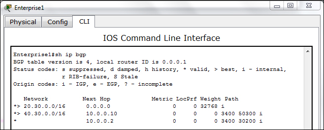
If you look at the Path column, you can see the ASNs that come in the path to the destination. The
>symbol indicates a preferred route.