Table of Contents for
Packet Tracer Network Simulator
 Packet Tracer Network Simulator
Published by
Packt Publishing, 2014
Packet Tracer Network Simulator
Published by
Packt Publishing, 2014
- Cover
- Table of Contents
- Packet Tracer Network Simulator
- Packet Tracer Network Simulator
- Credits
- About the Author
- About the Reviewers
- www.PacktPub.com
- Preface
- Who this book is for
- Conventions
- Reader feedback
- Customer support
- 1. Getting Started with Packet Tracer
- Installing Packet Tracer
- Interface overview
- Creating a simple topology
- Summary
- 2. Network Devices
- Customizing devices with modules
- Emulating WAN
- Accessing the CLI
- Summary
- 3. Generic IP End Devices
- Servers
- Other end devices
- Configuring end devices
- Summary
- 4. Creating a Network Topology
- Testing connectivity with PDUs
- Using the simulation mode
- Clustering a topology
- Summary
- 5. Navigating and Modifying the Physical Workspace
- Moving devices physically
- Managing cables and distances
- Customizing icons and backgrounds
- Summary
- 6. Configuring Routing with the CLI
- Dynamic routing protocols
- The Routing table
- Load sharing
- Summary
- 7. Border Gateway Protocol (BGP)
- BGP versus dynamic routing protocols
- Configuring BGP in Packet Tracer
- Summary
- 8. IPv6 on Packet Tracer
- IPv6 static and dynamic routing
- Using both IPv4 and IPv6
- Summary
- 9. Setting Up a Wireless Network
- Wireless networks and physical workspaces
- Summary
- 10. Configuring VLANs and Trunks
- InterVLAN routing with routers and layer 3 switches
- Switch-to-switch trunk links
- Analyzing broadcasts in the simulation mode
- Summary
- 11. Creating Packet Tracer Assessments
- The initial network
- The answer network
- Testing the activity
- Summary
- Index
We have finally reached the important part of networking—routing. Routing allows communication between multiple logical networks. When configuring routing on the command line of Packet Tracer—similar to configuring on physical hardware—you'll find that Packet Tracer offers a GUI to configure static and RIP routing protocols. In addition to this, we'll also see how load balancing works using the simulation mode, which will help you understand things better.
Static routing is the no-brainer method for configuring routing even though it requires more work. With Packet Tracer, static routing can be configured using the GUI alone. In this method, we configure a router with a destination and a gateway to reach it. So, each router in a topology should know the means to reach all destinations in the network, which requires manual work. Similarly, if a router is added or removed from the topology, all routers must be manually updated to reflect this.
Even if you do not know Cisco commands, this feature of Packet Tracer comes in handy. For this exercise, we will be using the topology shown in the following screenshot:.
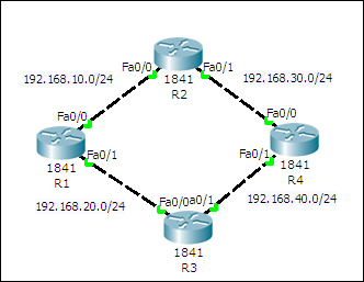
This network has four routers in a ring topology, with no PCs or loopback interfaces. Because we will be using only the GUI here, configuration will be kept to a minimum. The topology can be configured by performing the following steps:
- Click on a router icon, go to the Config tab, select an interface, and configure the IP address. Make sure that you select the On checkbox in this section to bring the port state up. For this example, we'll be using the following IP addresses:
Router
Interface
IP Address
R1
FastEthernet0/0
192.168.10.1FastEthernet0/1
192.168.20.1R2
FastEthernet0/0
192.168.10.2FastEthernet0/1
192.168.30.1R3
FastEthernet0/0
192.168.20.2FastEthernet0/1
192.168.40.1R4
FastEthernet0/0
192.168.30.2FastEthernet0/1
192.168.40.2 - Under the ROUTING section, click on Static. The following screenshot is displayed:
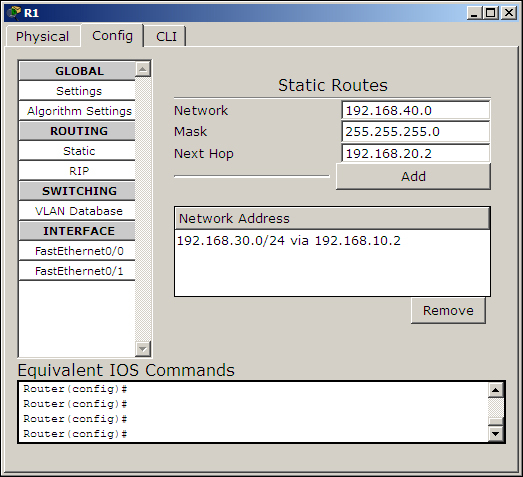
- The following settings will be used for configuring static routing using the GUI. The concept here is to enter all routes that are not directly connected to a router and a gateway IP that belongs to a network that is directly connected.
Device
Network/Mask
Next Hop
R1
192.168.30.0/255.255.255.0192.168.10.2192.168.40.0/255.255.255.0192.168.20.2R2
192.168.20.0/255.255.255.0192.168.10.1192.168.40.0/255.255.255.0192.168.30.2R3
192.168.10.0/255.255.255.0192.168.20.1192.168.30.0/255.255.255.0192.168.40.2R4
192.168.10.0/255.255.255.0192.168.30.1192.168.20.0/255.255.255.0192.168.40.1 - Now use simple PDU and test the connectivity between all of the routers. Then use the simulation mode to find the route taken by the packets.
- How about taking a look at the routing table? For this, too, the GUI has an option; click on the inspect icon or press I and select a router. A table containing four routes will appear for each router, as shown in the following screenshot:
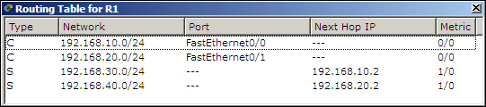
But we configured only two routes, so why four? The extra two routes are the subnets of the directly-connected links.
In this topology, even though there is an alternate route to each network, only one route is used because this is how we have configured it. We'll learn more about having more than one route in the Load Sharing section.
The configuration and the topology will be same in this section. We'll only see the commands required for one device. The topology can be configured by performing the following steps:
- Assign IP addresses to the interfaces on each router using the following commands:
R1(config)#interface FastEthernet0/0
R1(config-if)#ip address 192.168.10.1 255.255.255.0
R1(config-if)#no shutdown
R1(config-if)#exit
R1(config)#interface FastEthernet0/1
R1(config-if)#ip address 192.168.20.1 255.255.255.0
R1(config-if)#no shutdown
R1(config-if)#exit
- Configure static routing with the
ip routecommand, using the following syntax:R1(config)#ip route <Destination Prefix> <Destination prefix mask> <Gateway IP> - For router R1, the following commands are used:
R1(config)#ip route 192.168.30.0 255.255.255.0 192.168.10.2
R1(config)#ip route 192.168.40.0 255.255.255.0 192.168.20.2
Use simple PDU to test the connectivity. If you get message indicating a failure, switch to simulation mode and see which router is incorrectly configured.