Table of Contents for
Packet Tracer Network Simulator
 Packet Tracer Network Simulator
Published by
Packt Publishing, 2014
Packet Tracer Network Simulator
Published by
Packt Publishing, 2014
- Cover
- Table of Contents
- Packet Tracer Network Simulator
- Packet Tracer Network Simulator
- Credits
- About the Author
- About the Reviewers
- www.PacktPub.com
- Preface
- Who this book is for
- Conventions
- Reader feedback
- Customer support
- 1. Getting Started with Packet Tracer
- Installing Packet Tracer
- Interface overview
- Creating a simple topology
- Summary
- 2. Network Devices
- Customizing devices with modules
- Emulating WAN
- Accessing the CLI
- Summary
- 3. Generic IP End Devices
- Servers
- Other end devices
- Configuring end devices
- Summary
- 4. Creating a Network Topology
- Testing connectivity with PDUs
- Using the simulation mode
- Clustering a topology
- Summary
- 5. Navigating and Modifying the Physical Workspace
- Moving devices physically
- Managing cables and distances
- Customizing icons and backgrounds
- Summary
- 6. Configuring Routing with the CLI
- Dynamic routing protocols
- The Routing table
- Load sharing
- Summary
- 7. Border Gateway Protocol (BGP)
- BGP versus dynamic routing protocols
- Configuring BGP in Packet Tracer
- Summary
- 8. IPv6 on Packet Tracer
- IPv6 static and dynamic routing
- Using both IPv4 and IPv6
- Summary
- 9. Setting Up a Wireless Network
- Wireless networks and physical workspaces
- Summary
- 10. Configuring VLANs and Trunks
- InterVLAN routing with routers and layer 3 switches
- Switch-to-switch trunk links
- Analyzing broadcasts in the simulation mode
- Summary
- 11. Creating Packet Tracer Assessments
- The initial network
- The answer network
- Testing the activity
- Summary
- Index
The physical view adds a dimension of distance for wired and wireless devices. This is very useful for working out the placement of wireless devices.
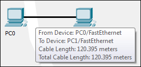
Measuring a cable is as easy as placing the pointer on a cable in the physical view (as shown in the following screenshot):
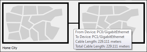
Standard copper Ethernet cables can extend up to a length of 100 meters; let's test this with the physical view:
- Create the same two PC topologies that we used previously (as shown in the following screenshot) but use the copper cable instead of the fiber one.
- In the physical view, move both the PCs to the intercity by following the instructions in the previous section.
- Navigate to the intercity and check the distance between them. If the distance is less than 100 meters, move them further apart, until the distance between them is more than 100 meters.
- Now come back to the logical view and you'll find that the link status of both the PCs is red because the connection came down due to the distance.
- Delete the link between the PCs and place a Repeater-PT from the hubs section. Connect both the PCs to the repeater with a copper straight-through cable. The link still remains down because this repeater was placed in the main wiring closet (which is still at a larger distance) that is very far from the intercity, as shown in the following screenshot:
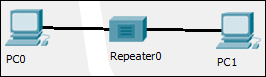
- Move to the physical view, navigate to the Main Wiring Closet and move the repeater to the intercity. Go to the intercity and place the hub between the two PCs. Now you'll find that the link comes up as the repeater boosts the signal.
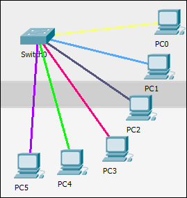
Let's move to the cable manipulation part of the physical workspace. Once you have a lot of devices, it becomes confusing to see which cable connects to what. Packet Tracer's physical workspace has a feature that allows cables to be color coded.
To color-code a cable, click on a wire in the physical view, choose Color Cable from the context menu, and pick a color from the Select Color dialog box. The following screenshot shows cables after they've been color coded:
The physical workspace also has a bend point creation feature that can be used to remove the tangled look of cables. To create a bend point, click on a cable and choose Create bendPoint from the context menu. Any number of bend points can be created on a single link, as shown in the following screenshot:
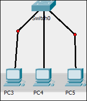
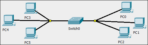
In addition, bend points can also be grouped together to form group points. To create a group point, drag a bend point and place it on another bend point. The red circle changes to a yellow square, as shown in the following screenshot:
To delete a bend point, use the delete tool from the Common Tools bar and click on the bend point. This removes only the bend point; the connection still remains.
To delete a group point, use the same delete tool and click on the group point. A context menu contains options to either ungroup a single bend point or to ungroup all. This removes only group points; the bend points remain as it is.