Table of Contents for
Packet Tracer Network Simulator
 Packet Tracer Network Simulator
Published by
Packt Publishing, 2014
Packet Tracer Network Simulator
Published by
Packt Publishing, 2014
- Cover
- Table of Contents
- Packet Tracer Network Simulator
- Packet Tracer Network Simulator
- Credits
- About the Author
- About the Reviewers
- www.PacktPub.com
- Preface
- Who this book is for
- Conventions
- Reader feedback
- Customer support
- 1. Getting Started with Packet Tracer
- Installing Packet Tracer
- Interface overview
- Creating a simple topology
- Summary
- 2. Network Devices
- Customizing devices with modules
- Emulating WAN
- Accessing the CLI
- Summary
- 3. Generic IP End Devices
- Servers
- Other end devices
- Configuring end devices
- Summary
- 4. Creating a Network Topology
- Testing connectivity with PDUs
- Using the simulation mode
- Clustering a topology
- Summary
- 5. Navigating and Modifying the Physical Workspace
- Moving devices physically
- Managing cables and distances
- Customizing icons and backgrounds
- Summary
- 6. Configuring Routing with the CLI
- Dynamic routing protocols
- The Routing table
- Load sharing
- Summary
- 7. Border Gateway Protocol (BGP)
- BGP versus dynamic routing protocols
- Configuring BGP in Packet Tracer
- Summary
- 8. IPv6 on Packet Tracer
- IPv6 static and dynamic routing
- Using both IPv4 and IPv6
- Summary
- 9. Setting Up a Wireless Network
- Wireless networks and physical workspaces
- Summary
- 10. Configuring VLANs and Trunks
- InterVLAN routing with routers and layer 3 switches
- Switch-to-switch trunk links
- Analyzing broadcasts in the simulation mode
- Summary
- 11. Creating Packet Tracer Assessments
- The initial network
- The answer network
- Testing the activity
- Summary
- Index
A switch breaks up collision domains and is a single broadcast domain. So how about breaking the single broadcast domains into multiple ones? VLAN (Virtual LAN) makes this possible and on a single switch we can have multiple broadcast domains. But once you create multiple VLANs on a switch, it becomes tedious to replicate the same configuration on all the other switches. This is where VTP (VLAN Trunking Protocol) comes in. So we have multiple switches with different VLANs and VTP, making management easier. But how do we make a device in one VLAN communicate with a device in another VLAN? We'll cover this in InterVLAN routing.
VLAN is a technology used to partition a single layer 2 network into multiple broadcast domains. This is done to restrict communication between devices that share the same broadcast medium. However, these devices can communicate with one another through a layer 3 device, such as a router. This is similar to connecting devices to different switches and then connecting them all to a router to separate broadcast traffic.
As more and more VLANs are created, it becomes tedious to replicate the configuration across all switches, which was why VTP was created.
We'll first learn about creating VLAN and assigning ports to it. VLAN 1 is created by default on all switches, and all ports reside in it. This VLAN is called the management VLAN.
To create a VLAN, use the following command:
Sw1(config)#vlan 2
The VLAN ID can be between 1 and 1001. The IDs 1002, 1003, 1004, and 1005 are reserved. Once this command has been entered, you are taken to the VLAN subconfiguration mode. This is the place where we can assign a name to the VLAN.
Sw1(config-vlan)#name finance
Assigning a name to a VLAN is optional; by default, the name is VLAN0002. Next, we will assign a few ports to this VLAN. To assign many ports to a single VLAN, the range command can be used, which then selects multiple interfaces.
Sw1(config)#interface range f0/10-20
To assign these ports to VLAN 2, use the following command:
Sw1(config-if-range)#switchport access vlan 2
Let's verify if the ports were indeed assigned to the correct VLAN.
Sw1#show vlan
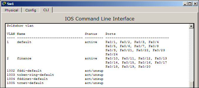
Note that in the above example, some of the output has been omitted for brevity.
We will now create a topology with three switches to demonstrate VTP. VTP has three modes: server, client, and transparent.
- Server: This is the default mode of VTP; in this mode, switches are allowed to modify their VLANs and send VTP advertisements.
- Client: In this mode, switches listen for VTP advertisements from other server switches. Client switches aren't allowed to modify their VLAN database locally.
- Transparent: This mode works independent of other switches. In this mode, the switch only forwards the VTP advertisements it receives and does not generate any, neither does it modify its own VLANs based on the VTP advertisements.
The following topology will be used for demonstration:
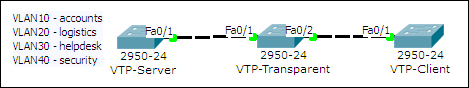
- In the first switch (VTP-Server), we will have four VLANs with different names. Then, we will set all the switch-switch ports to trunking.
VTP-Server(config)#interface Fa0/1
VTP-Server(config-if)#switchport mode trunk
VTP-Transparent(config)#interface range Fa0/1-2
VTP-Transparent(config-if-range)#switchport mode trunk
VTP-Client(config)#interface Fa0/1
VTP-Client(config-if)#switchport mode trunk
- Since VTP is already in server mode, we will just change the VTP domain name and set a password.
VTP-Server(config)#vtp domain My-Office
Changing VTP domain name from NULL to My-Office
VTP-Server(config)#vtp password s3cRet
Setting device VLAN database password to s3cRet
- Move on to the second switch (VTP-Transparent) and make it transparent.
VTP-Transparent(config)#vtp mode transparent - The final task is to move the third switch (VTP-Client) to client mode.
VTP-Client(config)#vtp mode client - You do not have to change the domain of this switch, as changing it to client will make it pick up the domain name from the server. However, it is necessary to set the VTP password.
VTP-Client(config)#vtp password s3cRet
The configuration is done; now, use the show vlan command on the VTP-Client switch to see the new VLANs. This example is only to demonstrate VTP. This topology won't allow normal communication between VTP-Server and VTP-Client, as the switch in the middle (VTP-Transparent) doesn't have any of the VLANs we configured.