Table of Contents for
Packet Tracer Network Simulator
 Packet Tracer Network Simulator
Published by
Packt Publishing, 2014
Packet Tracer Network Simulator
Published by
Packt Publishing, 2014
- Cover
- Table of Contents
- Packet Tracer Network Simulator
- Packet Tracer Network Simulator
- Credits
- About the Author
- About the Reviewers
- www.PacktPub.com
- Preface
- Who this book is for
- Conventions
- Reader feedback
- Customer support
- 1. Getting Started with Packet Tracer
- Installing Packet Tracer
- Interface overview
- Creating a simple topology
- Summary
- 2. Network Devices
- Customizing devices with modules
- Emulating WAN
- Accessing the CLI
- Summary
- 3. Generic IP End Devices
- Servers
- Other end devices
- Configuring end devices
- Summary
- 4. Creating a Network Topology
- Testing connectivity with PDUs
- Using the simulation mode
- Clustering a topology
- Summary
- 5. Navigating and Modifying the Physical Workspace
- Moving devices physically
- Managing cables and distances
- Customizing icons and backgrounds
- Summary
- 6. Configuring Routing with the CLI
- Dynamic routing protocols
- The Routing table
- Load sharing
- Summary
- 7. Border Gateway Protocol (BGP)
- BGP versus dynamic routing protocols
- Configuring BGP in Packet Tracer
- Summary
- 8. IPv6 on Packet Tracer
- IPv6 static and dynamic routing
- Using both IPv4 and IPv6
- Summary
- 9. Setting Up a Wireless Network
- Wireless networks and physical workspaces
- Summary
- 10. Configuring VLANs and Trunks
- InterVLAN routing with routers and layer 3 switches
- Switch-to-switch trunk links
- Analyzing broadcasts in the simulation mode
- Summary
- 11. Creating Packet Tracer Assessments
- The initial network
- The answer network
- Testing the activity
- Summary
- Index
So far, we have learned a lot about the devices available in Packet Tracer. In this chapter, we will start putting these devices to use. We'll learn what it takes to create a network topology, its connections, and link indications. Then we'll test the connectivity between the topologies and a PDU (Protocol Data Unit), both simple and complex. Once we are done with that, you'll no doubt be curious to see how data moves from one node to another. That will be taken care of by the simulation mode of Packet Tracer. Finally, we'll clean up our workspace a bit by using the clustering feature.
Choosing the Connections icon from the device-type selection box lists several cables in the device-specific selection box. Packet Tracer provides the following cables that can be used to connect devices:
- Console: This is a console cable that is used to view the network device's console from a PC/laptop. One end of the cable connects to the console port of a network device while the other one connects to the RS-232 port on a PC/laptop.
- Copper straight-through: This is a standard Ethernet cable that is used to connect two devices that operate in different layers of the OSI model (such as hub to router and switch to PC). It can be used with Ethernet, Fast Ethernet and Gigabit Ethernet port types.
- Copper cross-over: This Ethernet cable connects devices operating in the same OSI layer (such as hub to hub, PC to PC, PC to router, and PC to printer). This cable can also be used with Ethernet, Fast Ethernet and Gigabit Ethernet port types.
- Fiber: This cable connects Fast Ethernet and Gigabit Ethernet ports of a fiber port.
- Phone: This RJ11 cable connects the analog phone to a VoIP phone or a PC's modem to a cloud. It also connects the modem interface of routers.
- Coaxial: The coaxial cable connects the cloud with a cable modem and a TV with the cloud.
- Serial DCE and DTE: Serial cables connect routers together and connect routers to the cloud. The DCE (Data Circuit-terminating Equipment) end has a clock symbol on it. Clocking must be enabled on this end using the
clock rate <300-4000000>command to bring the line protocol up. If Serial DTE (Data Terminal Equipment) is chosen, the first device connected with this cable will be the DTE end and next device will be the DCE end. For the Serial DCE cable, this is just the opposite. - Octal: This cable was introduced in PT Version 6. It has a high-density connector on one end and eight RJ45 plugs on the other.
- Automatically choose connection type: If you are confused about the cable to use, choosing this option automatically connects two devices with the best cable. We say best cable because if you have two routers with serial and Fast Ethernet interfaces on both of them and want to connect both of their Fast Ethernet interfaces, choosing this option will connect only their serial interfaces together. Similarly, console ports cannot be connected using this option.
After connecting devices together, you'll find a light at each end of the cable; this indicates the state of the connection, as follows:
- Bright green: This indicates that the physical link is up, but it doesn't indicate the status of the line protocol.
- Blinking green: This indicates link activity.
- Red: This indicates that the physical link is down. This can be caused by incorrect cables or by a port being administratively shut down.
- Amber: This appears only on switches, and indicates that the port is running the STP (Spanning Tree Protocol) algorithm to detect layer 2 loops.
Let us demonstrate how to connect devices in a topology containing a PC, laptop, switch, and a router. We will be using the following topology for this demo:
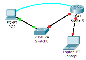
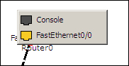
After adding the devices shown in the previous topology, click on a connection type from the device-type selection box and choose a connection. Click on a device and a context menu will list all of the interfaces available for the device. Select the interface and repeat the same steps on the other device to create a link between the two.
If a router is connected to any device, the link status will be red because routers have their ports in "shutdown" status by default. If a device is connected to a switch, the link is initially amber in color, indicating that it is going through the states of STP.