Table of Contents for
Electronics Cookbook
 Electronics Cookbook
Published by
O'Reilly Media, Inc., 2017
Electronics Cookbook
Published by
O'Reilly Media, Inc., 2017
- Cover
- nav
- Electronics Cookbook
- Electronics Cookbook
- Preface
- Theory
- Resistors
- Capacitors and Inductors
- Diodes
- Transistors and Integrated Circuits
- Switches and Relays
- Power Supplies
- Batteries
- Solar Power
- Arduino and Raspberry Pi
- Switching
- Sensors
- Motors
- LEDs and Displays
- Digital ICs
- Analog
- Operational Amplifiers
- Audio
- Radio Frequency
- Construction
- Tools
- Parts and Suppliers
- Arduino Pinouts
- Raspberry Pi Pinouts
- Units and Prefixes
- Index
- About the Author
- Colophon
Chapter 21. Tools
21.0 Introduction
This chapter explains how to use some of the most common electronic tools and test equipment. This includes both instruments for measurement such as multimeters and oscilloscopes and also simulation software that can be useful during design, especially when dealing with analog electronics.
21.1 Use a Lab Power Supply
Solution
To correctly use a lab power supply, follow these steps:
- Set the voltage to the voltage your circuit needs.
- Set the current limiting to slightly higher than the expected current consumption of your circuit.
- Turn on the output and watch the voltage display. If too much current is being drawn, the voltage will drop, indicating that something is wrong.
Discussion
Aside from a multimeter, the lab power supply is probably the most useful piece of test equipment you can own. Owning one will save you vast amounts of time in the long run because you won’t have to hunt around for batteries and cobble together power supplies and reduce the chance of accidental destruction of components when prototyping.
Figure 21-1 shows a typical lab power supply capable of supplying up to 22V at 5A.
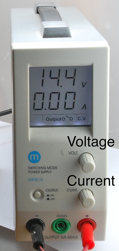
Figure 21-1. A Lab Power Supply
The top line of the display shows the voltage and the bottom, the current. When the output is off, the voltage knob allows you to set the voltage. The current knob sets the maximum current the circuit will be allowed to draw. If the circuit exceeds this, the power supply will automatically decrease the voltage until the current is below the set maximum. In this way, the power supply can be used as:
- Constant voltage with a maximum current
- Constant current with a maximum voltage
In addition to a single-output power supply like the one shown in Figure 21-1 dual-output power supplies are also available. These are very useful for analog circuits that require a split-voltage supply.
See Also
For information on building your power supplies of various sorts, see Chapter 7.
21.2 Measure DC Voltage
Solution
If you have an autoranging multimeter, simply set the meter to DC voltage and connect the probes across the voltage source.
If you have a multimeter where the range is set manually, determine the maximum voltage you expect to see and set the meter to the range whose maximum is above that value. Then connect the probe leads across the point in the circuit you want to measure.
Once you have established that the voltage is not too high for the range you selected, you can reduce the voltage range for better precision.
Discussion
Figure 21-2 shows a typical medium-range digital multimeter (DMM).
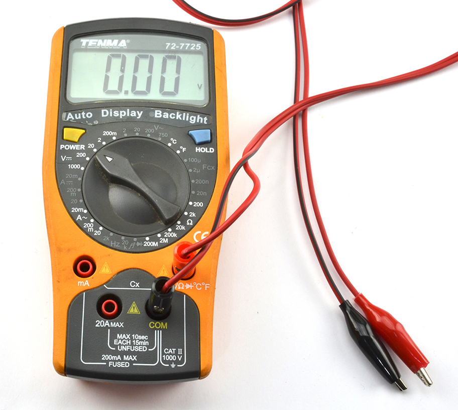
Figure 21-2. A Digital Multimeter
Although an autoranging multimeter might seem to be superior to a multimeter where the range has to be set, in practice, it can be an advantage to think about what reading you are expecting to see before you take the reading (manually setting the range forces you to do this).
Even very low-cost DMMs generally provide better precision and accuracy than an analog meter. The principle advantage of an analog meter is that you may get a few more clues about what you are measuring if, for example, the tip of the meter’s needle jitters slightly to indicate noise, or you can see the rate of change of voltage as the speed of the meter moving in one direction or another. Some DMMs try to give you the best of both worlds by including an “analog” bargraph-type display in addition to the digital display.
See Also
For measuring AC voltage, see Recipe 21.3.
21.3 Measure AC Voltage
Solution
Follow the same procedure as Recipe 21.2 except set the multimeter range to AC volts rather than DC volts.
Since you are measuring AC you will get the same polarity of reading no matter how the leads are placed onto the circuit.
If you are planning to measure high-voltage AC ensure your meter probes are rated for high voltage. Also see Recipe 21.12.
Discussion
Most DMMs will provide only an approximation of the RMS (root mean square) voltage by rectifying and smoothing it. Higher-end multimeters often include the feature “true RMS.”
See Also
For measuring DC voltages, see Recipe 21.2.
21.4 Measure Current
Solution
To use a multimeter to measure current:
- Set the meter’s range appropriately for AC/DC and at a higher range than the maximum current you expect.
- Fit the meter probes into the sockets indicated for current measurement. Note that these will be different sockets than for voltage measurement and there may be different sockets for different current ranges.
- Connect the leads to your circuit so the multimeter is in the current path. Figure 21-3 shows a DMM being used this way.
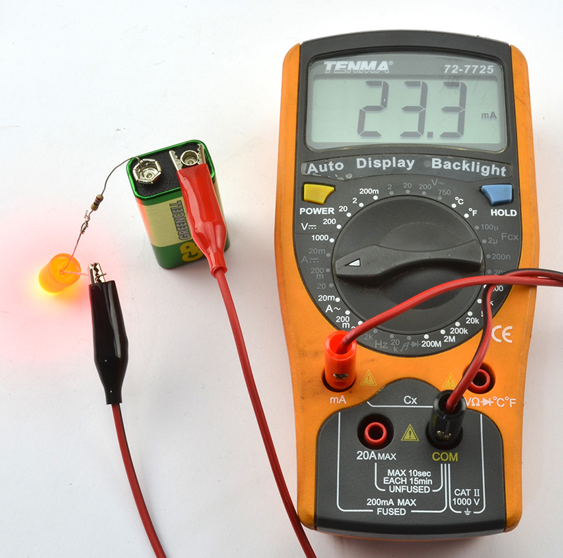
Figure 21-3. A Digital Multimeter Measuring Current
Discussion
DMMs measure the current flowing by measuring the voltage across a very low-value resistor. This is why you generally have to shift the probe leads to a different socket when measuring current.
Don’t Forget to Swap the Leads Back
If you leave the leads of the multimeter in their current measuring sockets and then go to measure voltage, you will effectively short-out the voltage you are trying to measure. This may damage the circuit or blow a fuse inside the multimeter.
To prevent this, always swap the leads back to their voltage-measuring positions when you are finished measuring current.
If you do blow the fuse in your multimeter, you should be able to open up your multimeter’s case and change the fuse.
See Also
To measure voltage, DC, and AC, see Recipe 21.2 and Recipe 21.3, respectively.
Most bench power supplies (Recipe 21.1) will also include an ammeter to tell you how much current is being drawn.
21.5 Measure Continuity
Solution
Disconnect the wire so that it is not in use and then use the continuity setting on your multimeter and connect the probes to each end of the thing you want to test.
If you are testing a long multicore cable (i.e., in situ and too long for the multimeter leads to reach both ends), you can connect the separate cores together at one end of the cable and test for continuity at the other, as shown in Figure 21-4.
Discussion
After DC voltage, continuity is probably the setting you are most likely to use on your multimeter. It is particularly useful if your multimeter makes a beeping noise when the resistance is low enough to indicate continuity. This allows you to move the test probes around without having to look at the multimeter’s screen.
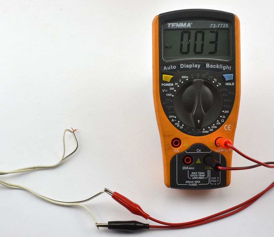
Figure 21-4. Testing a Long Cable for Continuity
See Also
Recipe 21.2 provides an introduction to multimeters.
21.6 Measure Resistance, Capacitance, or Inductance
Solution
Nearly all multimeters will have several resistance ranges, and many will have a few capacitance ranges as well.
To use these ranges, simply select the range and attach the component to the test leads. You may find that as with measuring current, the test leads have to be inserted into different sockets on the multimeter when using these measurement ranges.
Discussion
Some DMMs will offer inductance and frequency ranges, and specialized meters are available for measuring resistance, capacitance, and inductance more accurately than the average DMM can.
Some of these will actually allow you to just attach test leads to any component and the meter will first identify it and then measure its properties. Amazingly, such meters are available on eBay as a kit to assemble yourself for around $10.
When measuring component values, do not be seduced into thinking you are making a very accurate measurement of a component value because of the precision of the result. A reading of 1.23µF may still have a measurement of ±10%, so check the specification for your meter.
See Also
Recipe 21.2 provides an introduction to multimeters.
21.7 Discharge Capacitors
Solution
Disconnect the circuit and then use a resistor in parallel with the capacitor to discharge the capacitor until the voltage across it has reached a safe level as indicated by a multimeter set to its DC-voltage setting.
When discharging the capacitor, you can either connect the resistor using insulated crocodile clips, or if access is good enough, bend the resistor leads to the correct gap and then hold the resistor with pliers, carefully touching the capacitor leads as shown in Figure 21-5.
Calculate the resistance and the power rating of the resistor such that the capacitor discharges in a reasonable amount of time without the resistor becoming too hot.
The time constant (RC) is the time in seconds for the capacitor’s voltage to drop to 63.2% of its original value. For example, if you have a 100µF capacitor charged to 300V (you might find this in a photographic flashgun) and you want to discharge the capacitor to a safe 10V, a resistor of 10kΩ would have a time constant of 1 second. So holding it to the capacitor for 1 second would reduce the voltage to 190V, a further second to 120V, and so on. So, after 7 seconds, the voltage would be down to a safe 7.6V.
You can calculate the maximum power the resistor will dissipate as heat using:
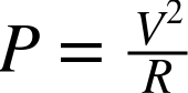
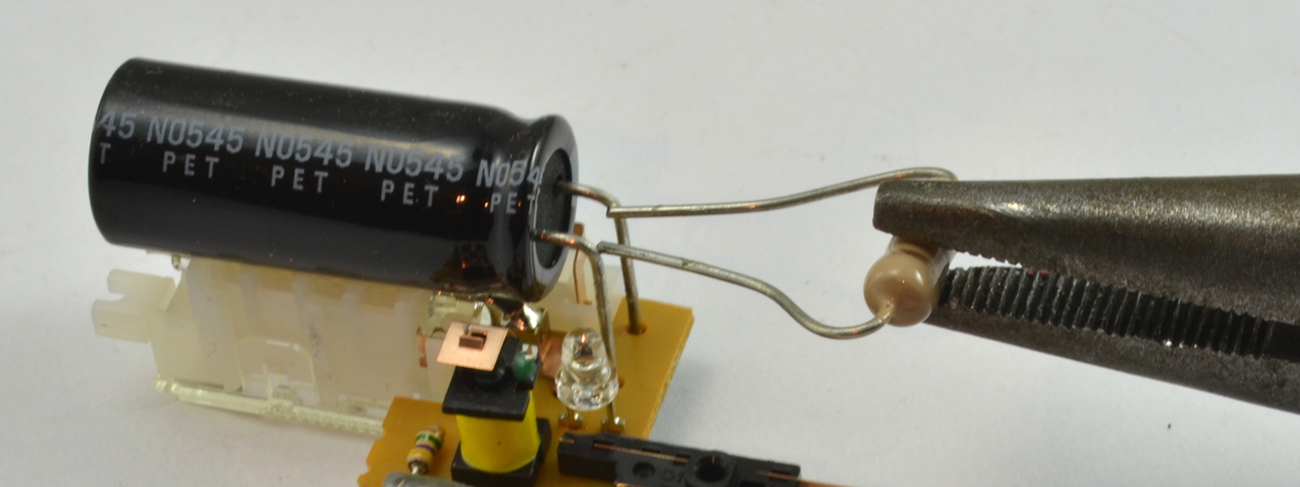
Figure 21-5. Discharging a Capacitor
which in this case would be 9W. That’s quite a physically big resistor, so failing to do a rough calculation and using a standard ¼W resistor is likely to end in a puff of smoke for the resistor.
Discussion
Increasing the resistance of the resistor decreases the power requirement of the resistor but will take longer for the capacitor to discharge. It is a good idea to monitor the capacitor’s voltage with a multimeter while you discharge.
A capacitor charged to a high voltage is a dangerous thing, but a high-value capacitor even at low voltages can cause massive currents to flow if its terminals are short circuited and the capacitor has a low ESR.
See Also
For a calculation on the energy stored in a capacitor, see Recipe 3.7.
21.8 Measure High Voltages
Solution
Use a voltage divider comprised of a ladder of equal-value resistors to reduce the voltage to be measured. You will need to take into account the effect that the voltage divider has on the voltage being measured and the input impedance of the multimeter. Also, make sure the resistors used are rated for a high enough voltage.
Figure 21-6 shows how you might measure a voltage of around 5kV using a multimeter with a maximum DC voltage measurement of 1000V and an imput impedance of 10MΩ.
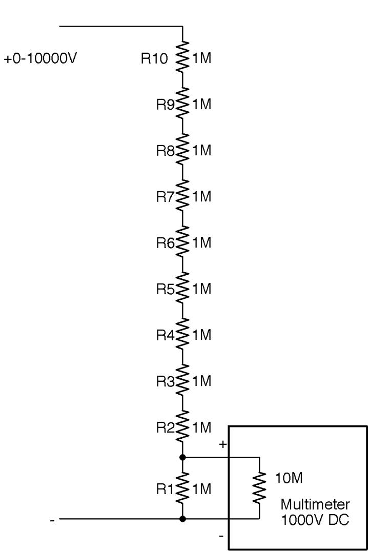
Figure 21-6. Measuring a High Voltage Using a Voltage Divider
The voltage divider will reduce the input voltage by a factor of 10, making the sums easier. Using 10 equal-value resistors (of 1% or better accuracy) is more likely to result in better accuracy of the system overall if the resistors are from the same batch. The closer the resistors are in value to each other the better the divider.
There are a few other things you need to consider. First, remember to calculate how much the chain of resistors will load the output of the high-voltage source. In this case, a load of 10MΩ across 10kV will result in current flowing at 1mA.
High-Voltage Leads
If you plan to measure high voltages, you will need special high-voltage leads that are extremely well insulated to prevent sparking across to your fingers. Your voltage divider should also be boxed and not easy to accidentally touch.
Also, see Recipe 21.12.
The heat power generated by each resistor will be 1kV * 1mA = 1W, which is significant. The temptation is to use higher-value resistors (say 10MΩ) to reduce the power and loading on the voltage source, but this will lead to the impedance of the multimeter becoming significant and acting as two similar-value resistors in parallel, making the reading almost useless.
A typical low-cost or medium-range multimeter will only have an input impedance of 10MΩ, which would result in the voltage reading being reduced by about 10% from the actual voltage.
Discussion
You can determine the input impedance of your multimeter using the schematic in Figure 21-7.
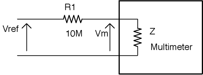
Figure 21-7. Finding the Input Impedance of Your Multimeter
To determine the input impedance of your multimeter (Z in Figure 21-7):
- Accurately measure the voltage of a stable voltage source—say a regulated 5V supply—by directly connecting the multimeter leads across it. Make a note of this value (Vref).
- Now place a resistor in series with the positive multimeter leads as shown in Figure 21-7 and see what voltage the meter reads now (Vm). If there is little or no change in the reading, then try a higher-value resistor (say 100MΩ) and congratulations you have a high-quality multimeter.
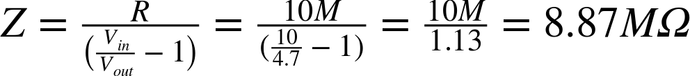
- Calculate the impedance of the meter (Z) using the formula:
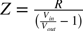
For example, with a value of R1 of 10MΩ and a 10V supply, my meter gave a Vm reading of 4.7V. Plugging the numbers in you get:
If you plan to measure high voltages on a regular basis, buy a specialist high-voltage voltmeter. In addition to having a very high voltage range, these instruments also usually have very high input impedance and do not load the circuit under test to the extent that the voltage being measured is appreciably altered.
You can also use the preceding method using very high-value resistors if you buy a high-quality multimeter with a buffered input that gives the multimeter an input impedance in the hundreds of MΩ or even GΩ range.
See Also
For more information on using a resistor as a voltage divider, see Recipe 2.6.
For regular DC-voltage measurement, see Recipe 21.2.
21.9 Use an Oscilloscope
Solution
Figure 21-8 shows a typical low-cost oscilloscope displaying a 1kHz 5V test signal available from a terminal on the front of the oscilloscope.
To look at a signal on an oscilloscope:
- Estimate the maximum signal voltage and set the y-axis gain to a value that will allow you to see the whole signal on the screen. For example, in this case the signal is 5V so setting the y-axis gain for the channel being used (channel A) to 2V/division (little square on the screen) will be fine. If in doubt, set the volts/division to its maximum value.
- Set the trigger level to a height up the screen where the changing signal will cause the scope to trigger, allowing you to see a stable image of the signal.
- Adjust the x-axis timebase until the signal is stretched out enough to see the shape of the waveform. In this case, the x-axis timebase is set to 500µS/division so one whole waveform occupies two divisions (1ms), confirming the frequency of 1kHz.
Discussion
Every model of oscilloscope is a little different, so you will need to consult the manual for yours to find the controls used in the preceding instructions.
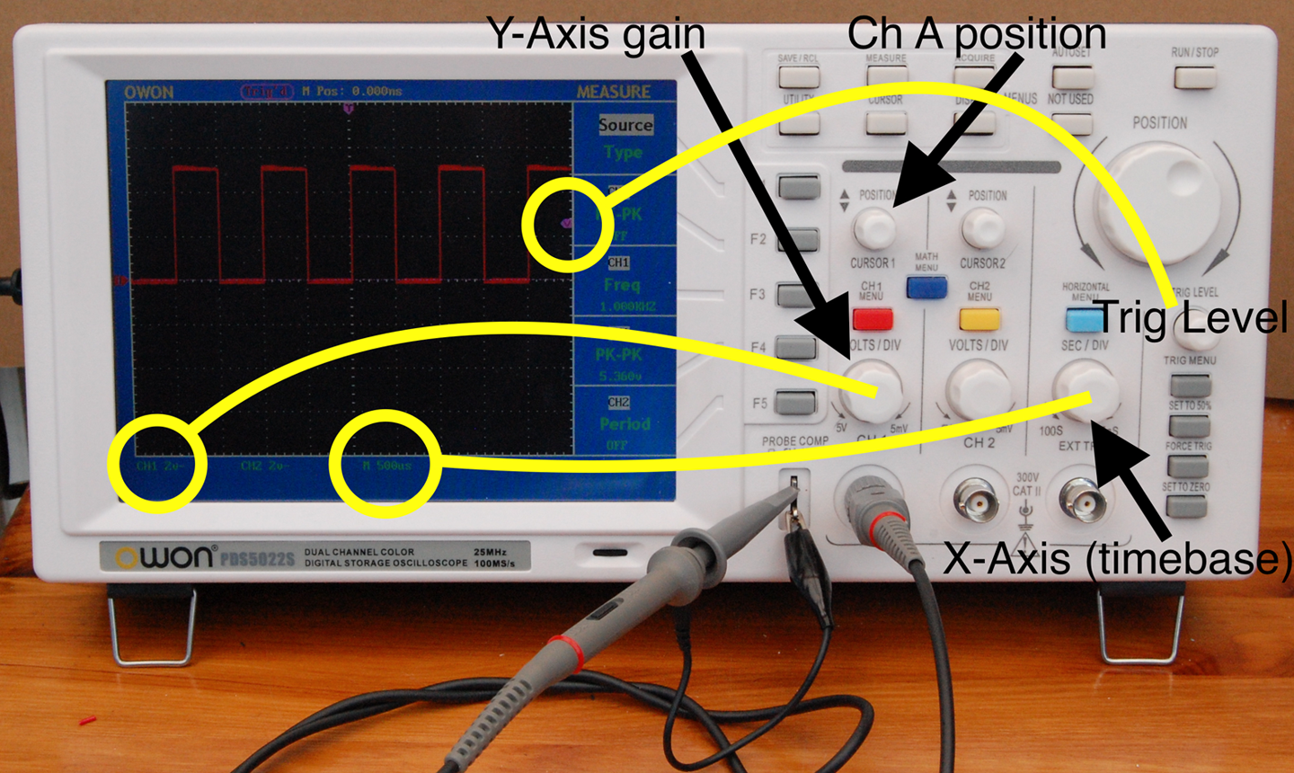
Figure 21-8. Displaying a Signal on an Oscilloscope
Most oscilloscopes, including the one shown in Figure 21-8, have two channels that allow you to display two signals at the same time as well as a host of other features such as automatic measurement of frequency and signal amplitude.
When choosing an oscilloscope to buy, you can spend from a few hundred dollars to many thousands of dollars. You pay more for higher frequency range, better displays, and more advanced features. A basic 20MHz oscilloscope like the one shown in Figure 21-8 is a perfectly good starting point and has served me well for many years.
In addition to standalone oscilloscopes, you can also buy “PC scopes” that do not have a screen but rather rely on a USB connection to the PC running the oscilloscope software. As with standalone oscilloscopes, PC scopes are available at all prices and qualities. I prefer a standalone device as it’s always there on my workbench and I don’t have to wait for it to boot up, but many people find the extra features that often come with a PC scope and the bigger and better display of a computer monitor outweigh any disadvantages.
See Also
For more information on getting the most from your oscilloscope, get to know the manual really thoroughly. You may find all sorts of features that are not immediately obvious from the controls on the front.
21.10 Use a Function Generator
Solution
Use a function generator (a.k.a. a signal generator).
The function generator shown in Figure 21-9 is a typical low-cost function generator capable of generating two independent sine, square, or triangle waveforms of up to 20 MHz.
To use the function generator:
- Turn its output off
- Set the waveform you want (sine and square are the most common)
- Set the p-p (peak-to-peak) amplitude
- Set the DC offset
- Optionally attach one channel of an oscilloscope to the signal and test it appears as expected by turning on the signal generator’s output for a moment
- Connect the signal-generator output to the input of the circuit you are testing
- Turn the signal-generator output on
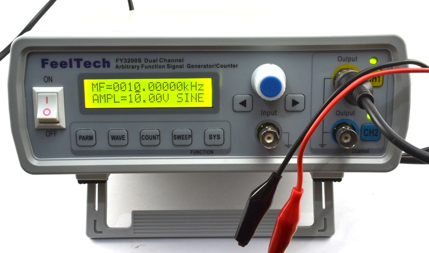
Figure 21-9. A Low-cost DDS (Direct Digital Synthesis) Function Generator
Don’t Forget DC Offset
If you have a single-supply amplifier or other circuit, if the input signal is swinging negative on each cycle, you may damage the circuit you are testing.
Signal generators with digital controls, like the one shown in Figure 21-9, assume a full AC signal and a DC offset have to be explicitly set.
Discussion
Figure 21-10 shows the oscilloscope trace for a 10kHz sinewave with an amplitude of 2V peak-to-peak and a DC offset of 2.5V generated by the function.
See Also
If you are on a budget, you can make your own oscillator as shown in Recipe 16.5.
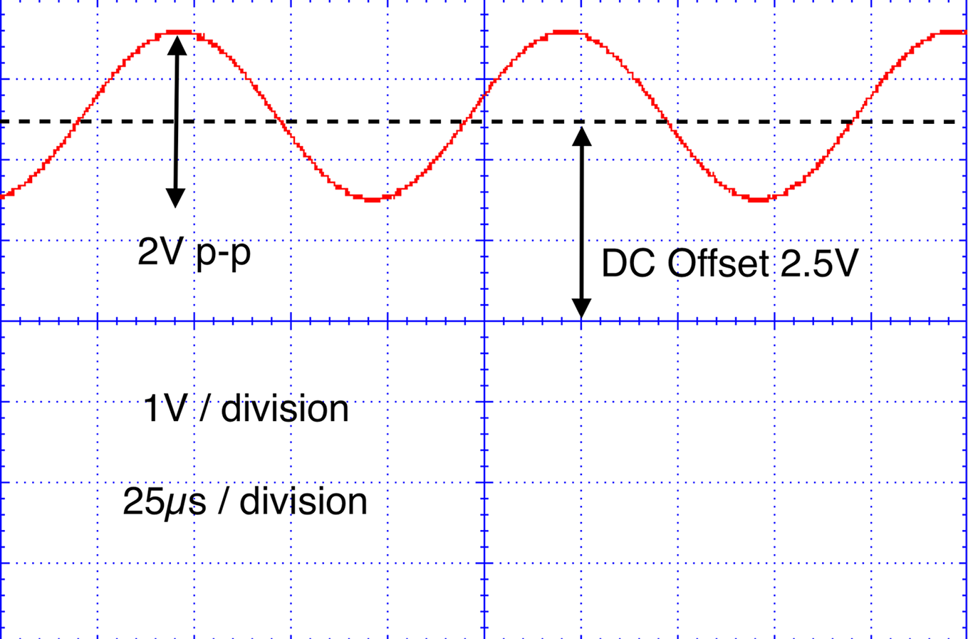
Figure 21-10. Waveform Amplitude and DC Offset
21.11 Simulation
Solution
Use circuit-simulator software.
A free online circuit simulator is a great way to get started with circuit simulation. The PartSim is one such easy-to-use simulator. Sign up for a PartSim account and then start drawing your schematic in the simulator. Figure 21-11 shows the schematic for the simple RC filter from Recipe 16.3.
In addition to drawing R1 and C1, you can also specify an AC-voltage source to drive it. In this case, as the parameter in Figure 21-11 suggests, the test signal will be a 5V square wave (pulse) with rise and fall times of 1µs, a pulse length of 15µs, and an overall period of 30µs. This corresponds roughly to the 32.7kHz carrier signal of Recipe 16.3.
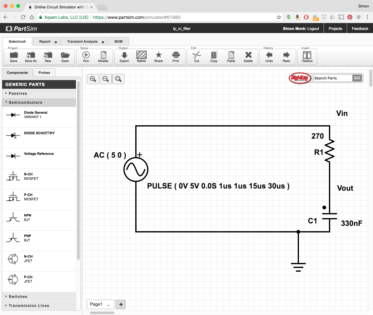
Figure 21-11. PartSim Schematic Editor
When you click the Run button you will be prompted to enter some parameters for a simulation as shown in Figure 21-12.
There are various types of simulations that can be run, but in this case we are interested in the “Transient Response.” The Start and Stop times determine how long the simulation will run and the Time Step is the step between each calculated value in the simulation.
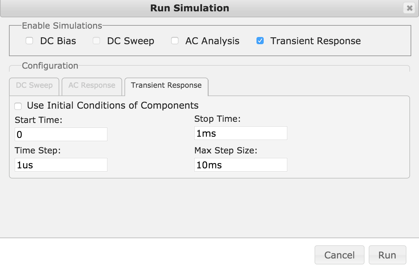
Figure 21-12. Simulation Parameters
When you click Run, you will see a new tab appear in the window with the name “transient response” that shows the result of the simulation as shown in Figure 21-13.
You can see that the output is indeed greatly attenuated by the RC filter.
Discussion
Simulation is very useful in analog design, not least because it tells you how the circuit should behave, whereas a signal generator and oscilloscope will tell you how just one prototype behaves. A physical prototype has the problem that there may be a fault in its construction or components that causes it to behave differently when you make a second prototype. Simulation will tell you what to expect in a reliable and consistent manner.
In addition to idealized components like resistors, capacitors, and perfect op-amps, simulators like PartSim also have a huge array of “models” for actual components, including specific op-amp models.
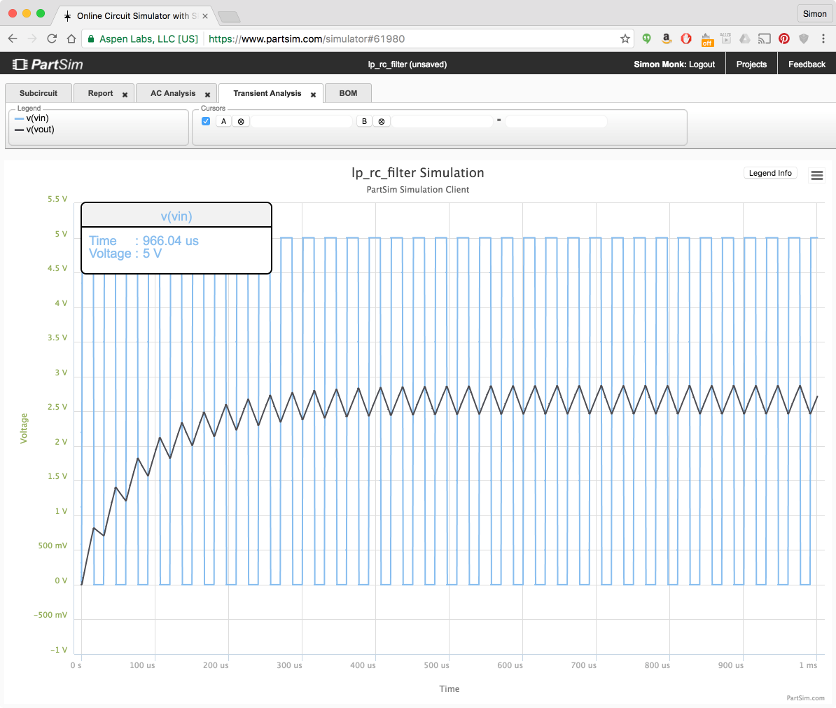
Figure 21-13. PartSim Simulation Results
See Also
PartSim is based on the open source SPICE simulation software; learn more at: http://bwrcs.eecs.berkeley.edu/Classes/IcBook/SPICE/.
21.12 Working Safely with High Voltages
Solution
Assume that coming into contact with a high voltage will kill you.
Although a little hyperbolic, this statement is a good thing to keep at the front of your mind when working with high voltages. Frankly anything above 50V should scare you. So AC with its fatal combination of high voltage and high availability of current should scare you a lot.
Here are some rules I stick to when working on AC:
- If you are not sure you have the skills and experience to work on AC, find a friend to help you who does, or do something else.
- Never work on a project while it is connected to AC. I actually put the plug in front of me, so that I can see it’s not plugged in. Don’t rely on the outlet switch.
- Don’t do this kind of work if you feel tired. That’s when mistakes happen.
- Always discharge any capacitors in the project (see Recipe 21.7).
- If you make a project using high voltages, always make sure it is enclosed so that other people cannot accidentally get shocked.
- Connect any metal of your project to earth.
- Use standard connectors (such as “kettle leads”) that are correctly rated for the voltage and current you are using.
- Think about what you are doing and check everything before you power up.
Discussion
According to the American Burn Association:
In the United States, on average of 400 people die from electrocution and 4,400 are injured each year because of electrical hazards.
In addition to the risk of a current flowing through your heart and stopping it, burns caused by your body effectively acting as a heating element as well as arcing sparks are risks associated with high voltages.
See Also
For the full American Burn Association report, see: http://www.ameriburn.org/Preven/ElectricalSafetyEducator’sGuide.pdf.