Table of Contents for
Electronics Cookbook
 Electronics Cookbook
Published by
O'Reilly Media, Inc., 2017
Electronics Cookbook
Published by
O'Reilly Media, Inc., 2017
- Cover
- nav
- Electronics Cookbook
- Electronics Cookbook
- Preface
- Theory
- Resistors
- Capacitors and Inductors
- Diodes
- Transistors and Integrated Circuits
- Switches and Relays
- Power Supplies
- Batteries
- Solar Power
- Arduino and Raspberry Pi
- Switching
- Sensors
- Motors
- LEDs and Displays
- Digital ICs
- Analog
- Operational Amplifiers
- Audio
- Radio Frequency
- Construction
- Tools
- Parts and Suppliers
- Arduino Pinouts
- Raspberry Pi Pinouts
- Units and Prefixes
- Index
- About the Author
- Colophon
Chapter 13. Motors
13.0 Introduction
This chapter looks at various types of motors and how both their speed and direction can be controlled. This involves the electronics of controlling fairly high load currents as well as the software needed. This chapter will cover examples for Arduino and Raspberry Pi.
When people talk of motors, what tends to spring to mind are the small DC motors that you might find in a battery-powered toy car. DC motors are common and often combined with a gearbox to reduce their high speed of rotation into a single unit called a gearmotor.
Stepper motors operate on a different principle and are found in printers of all sorts including 3D printers as they can be advanced in small steps (typically 1/200 of a revolution or more).
Servomotors fit a different niche, allowing accurate positioning of their “arm” in a restricted range of angles (about 180°). Servomotors are often found controlling the steering of a remote-control car or the control surfaces of a remote-control plane or helicopter.
All of these types of motors are available in various sizes to meet the power requirements of different applications. Whatever the size, controlling such motors follows the same basic principles.
13.1 Switch DC Motors On and Off
Solution
Use a transistor switch, but add a snubbing diode as shown in Figure 13-1. This is based on Recipe 11.1, which is fine for a small DC motor. For higher currents use a power MOSFET as described in Recipe 11.3.
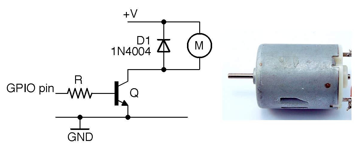
Figure 13-1. Schematic for Switching a DC Motor Alongside a 6V DC Motor
Discussion
The diode D1 prevents the transistor from being damaged. A “snubbing” diode like this should always be used to protect a switching transistor from excessive reverse voltage that occurs when the inductive load of the motor releases stored energy as a pulse of voltage in the opposite polarity to that in which it was driven. This reverse voltage is called “back-emf.”
It is not usually necessary to use a snubbing diode with a power MOSFET, because these devices have built-in diodes to prevent damage from electrostatic discharge, which will also protect against voltage spikes. They are (at least for relatively modest motors) sufficient to protect the transistor. However, adding a diode as you would with a BJT is the safest thing to do.
If you want to wire up the circuit of Figure 13-1, you can use the test programs in Recipe 11.6 and Recipe 11.7 to control a motor from an Arduino or Raspberry Pi.
See Also
Many of the techniques described in Chapter 11 can be used to switch a motor.
To control the speed of a motor, see Recipe 13.2.
13.2 Measure the Speed of a DC Motor
Solution
Using a transistor switch and PWM to adjust the speed of the motor, measure the motor’s speed using an optical detector and slotted wheel attached to the shaft of the motor.
You can use the schematic in Figure 13-2 and pulse the GPIO control pin with PWM as described in Recipe 10.13 and Recipe 10.14.
Discussion
Using PWM to control a motor actually controls the power supplied to the motor rather than its speed, but assuming the motor’s load remains constant, these amount to the same thing.
Measuring the motor speed requires a sensor that does not interfere with the rotation of the motor. One way to do this is to use an optical sensor like the prebuilt model shown in Figure 13-2 along with a laser-cut disk that has slots in it. As the disk rotates it alternately blocks and allows light to pass, resulting in a series of pulses that can be used to determine both the speed of the motor and the number of rotations it has made.
The optical sensor includes a built-in comparator and has an “open collector” (Recipe 11.11) output that requires a 1kΩ pull-up resistor to 5V. These sensors are readily available from eBay for a few dollars.
The motor-control circuit uses a MOSFET in the circuit described in Recipe 11.3.
The sketch ch_13_motor_speed_feedback (see Recipe 10.2) reports the speed of the motor in RPM (revolutions per minute) once every second in the Serial Monitor. It also allows you to send a PWM value of 0 to 255 to control the speed of the motor.
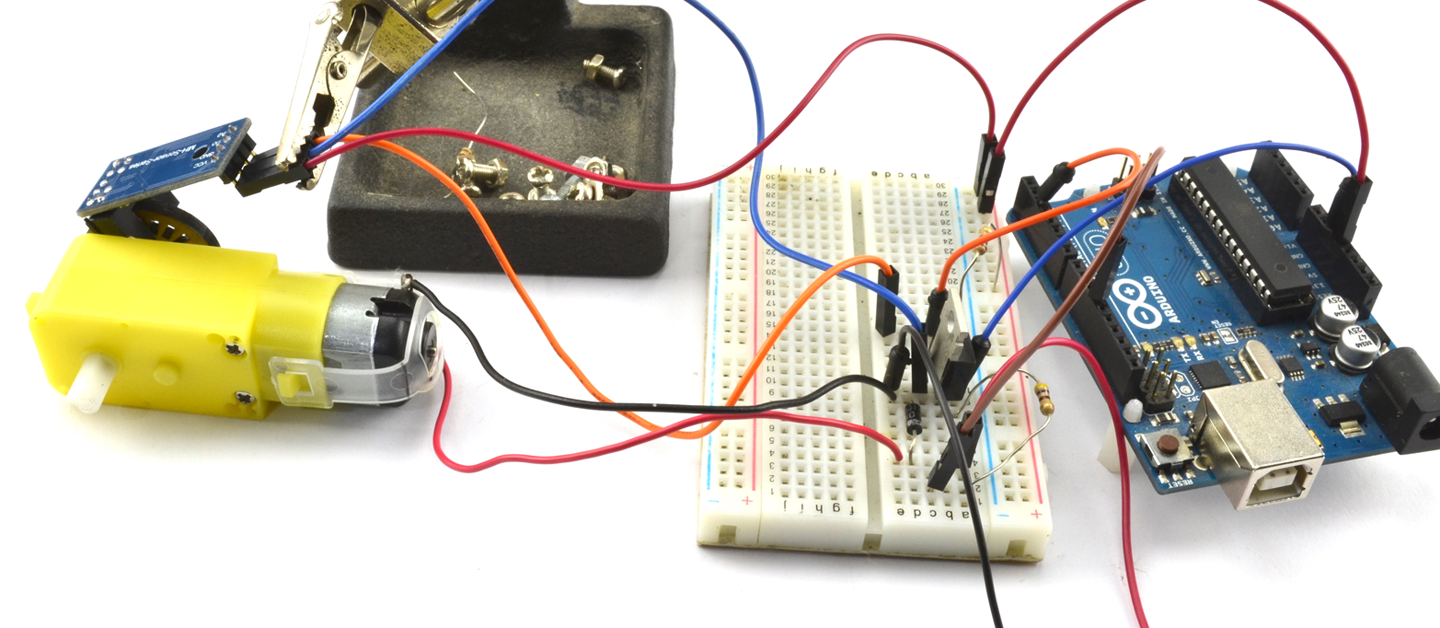
Figure 13-2. Measuring Motor Speed
Make sure that the Line endings drop-down list of the Serial Monitor is set to “No line ending.”
constintoutputPin=11;constintsensePin=2;constintslotsPerRev=20;constlongupdatePeriod=1000L;// mslonglastUpdateTime=0;longpulseCount=0;floatrpm=0;voidsetup(){pinMode(outputPin,OUTPUT);Serial.begin(9600);Serial.println("Enter speed 0 to 255");attachInterrupt(digitalPinToInterrupt(sensePin),incPulseCount,RISING);}voidloop(){if(Serial.available()){intsetSpeed=Serial.parseInt();analogWrite(outputPin,setSpeed);}updateRPM();}voidincPulseCount(){pulseCount++;}voidupdateRPM(){longnow=millis();if(now>lastUpdateTime+updatePeriod){lastUpdateTime=now;rpm=float(pulseCount)*60000.0/(20.0*updatePeriod);pulseCount=0;Serial.println(rpm);}}
An interrupt is used so that every time the sensePin goes from LOW to HIGH the function incPulseCount is called that increments the value of pulseCount.
The function updateRPM will use pulseCount to calculate the RPM once per second before resetting pulseCount to 0.
See Also
To just turn a motor on and off, see Recipe 13.1, and to control the direction of a DC motor, see Recipe 13.3.
13.3 Control the Direction of a DC Motor
Solution
Use an H-bridge circuit that consists of two push-pull drivers. To keep the number of components low, this is normally accomplished using an H-bridge IC. Figure 13-3 shows the schematic for using the popular L293D motor controller with an Arduino to control two DC motors independently.
The L293D has separate voltage supplies for the ICs logic (VCC1) and the motor (VCC2). This allows the motor to operate at a different voltage than the logic and also reduces the problem of electrical noise caused by the motor disrupting the logic.
Speed control of the motors is accomplished by using a PWM signal to drive the 1,2EN and 3,4EN pins that enable the push-pull drivers in pairs. The direction of one motor is controlled by the L293D pins 1A and 2A and the second motor by 3A and 4A. Table 13-1 shows the four possible states of motor drive for the control pins 1A and 2A.
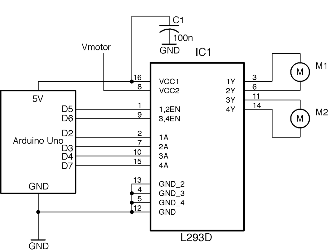
Figure 13-3. Using an L293D IC to Control Two Motors
| 1A | 2A | Motor M1 |
|---|---|---|
| LOW | LOW | Off |
| LOW | HIGH | Clockwise |
| HIGH | LOW | Counter-clockwise |
| HIGH | HIGH | Fast-stop |
Arduino software
To control the motors, three Arduino pins are needed for each motor. One to control the speed and two for the A and B control pins for the direction that are connected to the 1A and 2A control pins for one motor and the 3A and 4A pins of the L293 for the other.
constintmotor1SpeedPin=5;constintmotor2SpeedPin=6;constintmotor1DirAPin=2;constintmotor1DirBPin=3;constintmotor2DirAPin=4;constintmotor2DirBPin=7;voidsetup(){pinMode(motor1SpeedPin,OUTPUT);pinMode(motor2SpeedPin,OUTPUT);pinMode(motor1DirAPin,OUTPUT);pinMode(motor1DirBPin,OUTPUT);pinMode(motor2DirAPin,OUTPUT);pinMode(motor2DirBPin,OUTPUT);Serial.begin(9600);// M1 full speed clockwiseanalogWrite(motor1SpeedPin,255);digitalWrite(motor1DirAPin,LOW);digitalWrite(motor1DirBPin,HIGH);// M2 half speed counter-clockwiseanalogWrite(motor2SpeedPin,127);digitalWrite(motor2DirAPin,HIGH);digitalWrite(motor2DirBPin,LOW);}voidloop(){}
The code sets all the control pins to be outputs and then sets one motor to go at full speed in one direction and the other at half speed in the other. Try experimenting with this code to make the motors behave differently.
Raspberry Pi software
The 3.3V digital outputs of a Raspberry Pi will work just fine connected to the L293D, but the logic supply to the L293D must be 4.5V or more, so the 5V pin of the Raspberry Pi GPIO connector should be used. Table 13-2 shows the connections between Raspberry Pi and L293D.
| Raspberry Pi GPIO Pin | L293D Pin Name | L293 Pin Number(s) | Function |
|---|---|---|---|
| 5V | VCC1 | 16 | Logic supply |
| GND | GND | 12 | Ground |
| GPIO18 | 1,2EN | 1 | M1 speed |
| GPIO23 | 3,4EN | 9 | M2 speed |
| GPIO24 | 1A | 2 | M1 direction A |
| GPIO17 | 2A | 7 | M1 direction B |
| GPIO27 | 3A | 10 | M2 direction A |
| GPIO22 | 4A | 15 | M2 direction B |
The following Python programs (ch_13_l293d.py) will set M1 to operate at full speed in one direction and M2 at half-speed in the other direction:
importRPi.GPIOasGPIOGPIO.setmode(GPIO.BCM)# Define pinsmotor_1_speed_pin=18motor_2_speed_pin=23motor_1_dir_A_pin=24motor_1_dir_B_pin=17motor_2_dir_A_pin=27motor_2_dir_B_pin=22# Set pin modesGPIO.setup(motor_1_speed_pin,GPIO.OUT)GPIO.setup(motor_2_speed_pin,GPIO.OUT)GPIO.setup(motor_1_dir_A_pin,GPIO.OUT)GPIO.setup(motor_1_dir_B_pin,GPIO.OUT)GPIO.setup(motor_2_dir_A_pin,GPIO.OUT)GPIO.setup(motor_2_dir_B_pin,GPIO.OUT)# Start PWMmotor_1_pwm=GPIO.PWM(motor_1_speed_pin,500)motor_1_pwm.start(0)motor_2_pwm=GPIO.PWM(motor_2_speed_pin,500)motor_2_pwm.start(0)# Set one motor to full speedmotor_1_pwm.ChangeDutyCycle(100)GPIO.output(motor_1_dir_A_pin,False)GPIO.output(motor_1_dir_B_pin,True)# Second motor to half speedmotor_2_pwm.ChangeDutyCycle(50)GPIO.output(motor_2_dir_A_pin,True)GPIO.output(motor_2_dir_B_pin,False)input("Enter '0' to stop ")("Cleaning up")GPIO.cleanup()
The code follows the same pattern as its Arduino counterpart. First, the pins are set to be outputs and then two PWM channels are defined to control the motor speeds. Finally, one motor is set to full speed in one direction and the other to half-speed in the other direction.
The function GPIO.cleanup() sets all the pins to be inputs just before the program exits to stop both motors.
Discussion
Figure 13-4 shows a “schematic” for what is going on with an H-bridge driver. Don’t try and build this schematic; if you do, prepare for the possibility of destroying some of the transistors if Q1 and Q2 or Q3 and Q4 are turned on at the same time. Also, this circuit will only stand a chance of working if the motor voltage is almost the same as the logic voltage of the control pins (see Recipe 11.4).
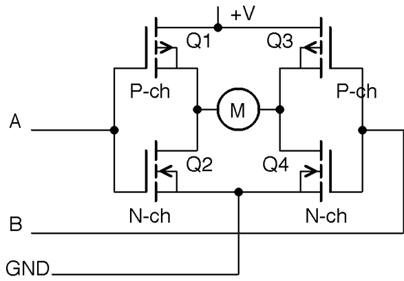
Figure 13-4. A Crude H-Bridge Driver
The idea of the circuit is that the control pin A makes Q1 conduct if it is LOW and Q2 conduct if it is HIGH. Similarly control pin B makes Q3 conduct if it is low and Q4 conduct if pin B is HIGH.
By setting A and B, you can control the direction of flow of current through the motor according to Table 13-1.
See Also
For more information on push-pull (half-bridge) drivers, see Recipe 11.8.
13.4 Setting Motors to Precise Positions
Solution
A servomotor offers the solution to this problem. Wire the servomotor up as shown in Figure 13-5.
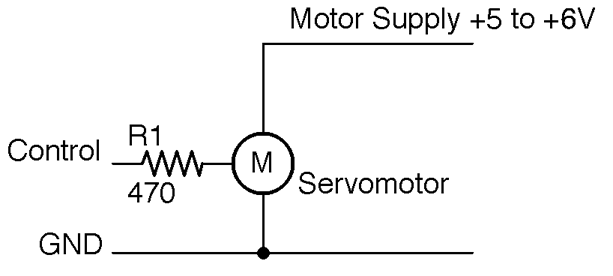
Figure 13-5. Connecting a Servomotor to a GPIO Pin
Generally servomotors will use a separate power supply from the supply used by the Arduino or Raspberry Pi, as the large load current as the motor starts may well drop the supply voltage enough to reset the controlling device. However, for a small lightly loaded servomotor, you may get away with using the same supply for both.
The resistor R1 is there to protect the GPIO pin, but is not strictly necessary as most servomotors draw very little current from the control pin. But if you do not have the datasheet for the servo you are using then R1 is a sensible precaution.
Figure 13-6 shows a small 9g hobby servo. The connector to the servo is fairly standardized, but you should also check the servomotor’s datasheet.
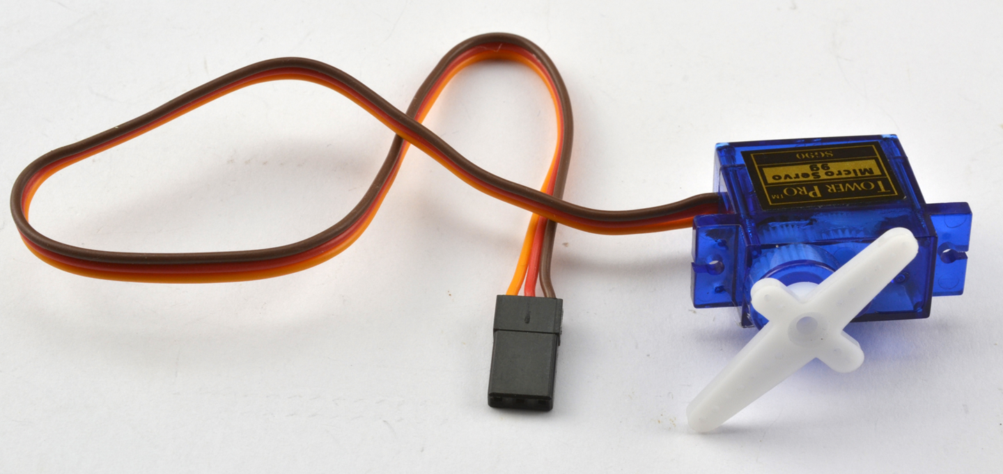
Figure 13-6. A 9g Servomotor
The red lead is the positive supply to the motor, the brown lead the ground connection, and the orange lead the control signal.
The control signal will normally be fine with a 3.3V logic, but if the datasheet for the servomotor indicates that this needs to be higher, use a level converter (Recipe 10.17).
Arduino software
The following example code (ch_13_servo) in the downloads for the book (see Recipe 10.2) assumes that the control pin of a servo is connected to pin 9 of an Arduino Uno.
When you open the Arduino Serial Monitor you will be prompted to enter an angle for the servoarm:
#include <Servo.h>constintservoPin=9;Servoservo;voidsetup(){voidsetup(){servo.attach(servoPin);servo.write(90);Serial.begin(9600);Serial.println("Angle in degrees");}voidloop(){if(Serial.available()){intangle=Serial.parseInt();servo.write(angle);}}
Make sure that you have Line endings drop-down on the Serial Monitor set to “No line ending.”
The servo.write method of the servo library sets the servo arm to an angle in degrees between 0 and 180.
Raspberry Pi software
The Raspberry Pi equivalent of the Arduino sketch is ch_13_servo.py in the book downloads (see Recipe 10.4):
importRPi.GPIOasGPIOimporttimeservo_pin=18# Tweak these values to get full range of servo movementdeg_0_pulse=0.5# msdeg_180_pulse=2.5# msf=50.0#50Hz = 20ms between pulses# Do some calculations on the pulse width parametersperiod=1000/f# 20msk=100/period# duty 0..100 over 20msdeg_0_duty=deg_0_pulse*kpulse_range=deg_180_pulse-deg_0_pulseduty_range=pulse_range*kGPIO.setmode(GPIO.BCM)GPIO.setup(servo_pin,GPIO.OUT)pwm=GPIO.PWM(servo_pin,f)pwm.start(0)defset_angle(angle):duty=deg_0_duty+(angle/180.0)*duty_rangepwm.ChangeDutyCycle(duty)try:whileTrue:angle=input("Angle (0 to 180): ")set_angle(angle)finally:("Cleaning up")GPIO.cleanup()
The set_angle function makes use of the variables deg_0_duty and duty_range, which are calculated once at the start of the program to calculate the duty cycle that will generate a pulse of the right length for the specified angle.
Servomotors rarely have exactly the same range of movement, so this program and its Arduino equivalent are a great way to find the range of angles that your servomotor can reach.
Discussion
Figure 13-7 shows how the pulses arriving at a servomotor’s control pin alter the angle of the servomotor’s arm.
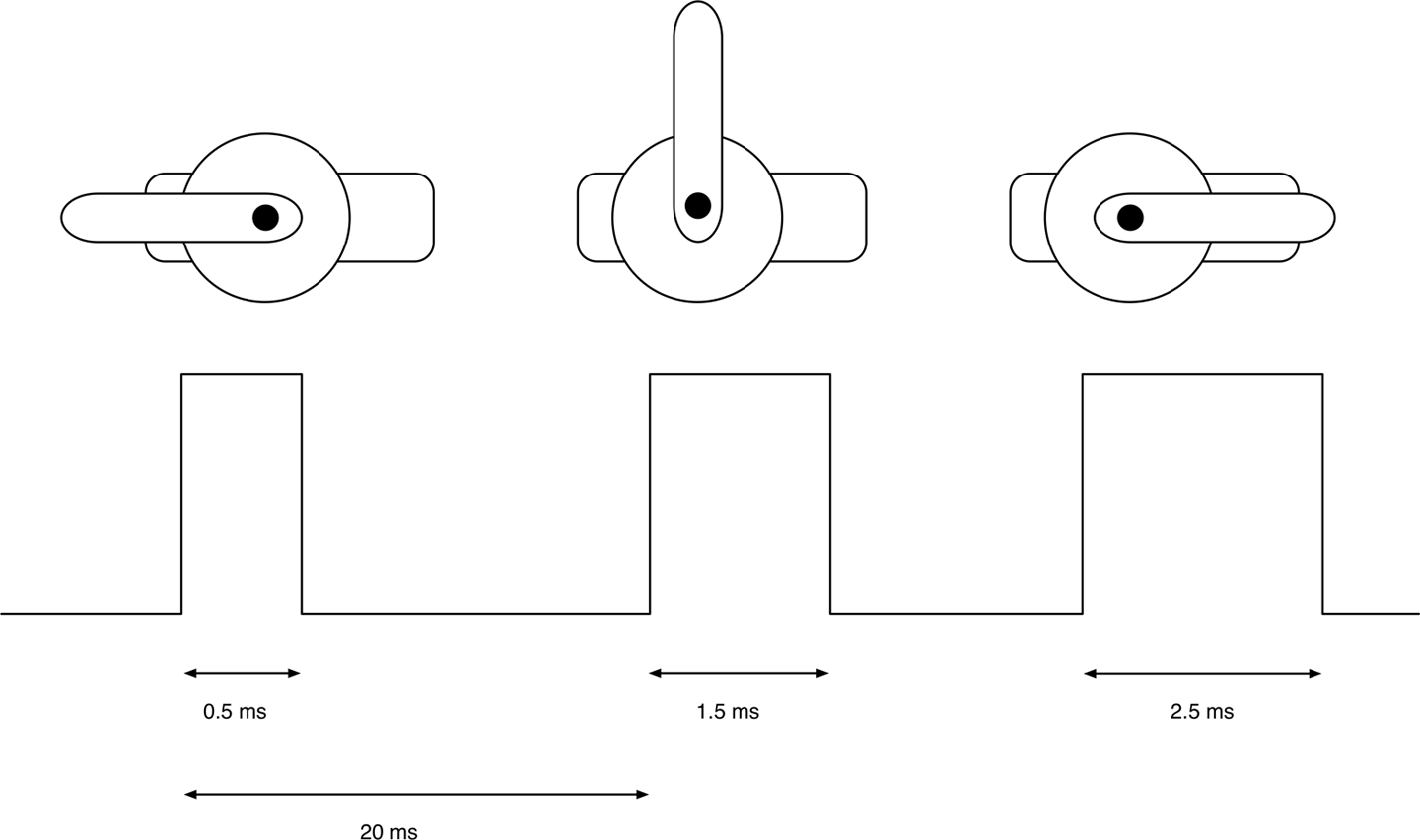
Figure 13-7. Pulse-Length Controls Position of Arm on a Servomotor
The servomotor expects a pulse every 20ms to maintain its position. The length of that pulse determines the position of the servomotor’s arm, which can normally travel through about 180°. A short pulse of between 0.5 and 1ms will position the arm at one end of its travel. A pulse of 1.5ms will position the servomotor’s arm in the center position and a long pulse of up to 2.5ms at its furthest travel.
Connect Lots of Servos
If you have a lot of servomotors to connect to an Arduino or a Raspberry Pi, then it can help to use a servomotor interface board such as the ServoSix board (Figure 13-8).
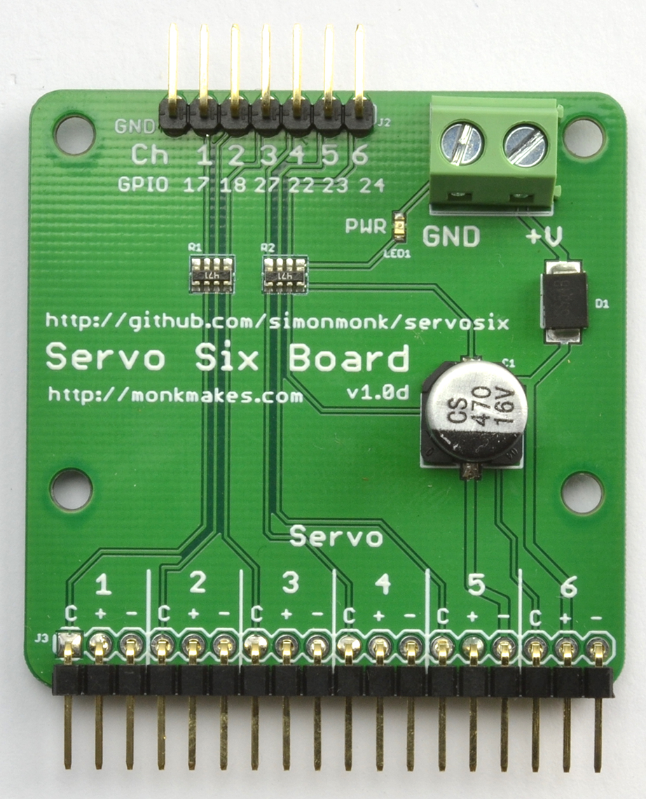
Figure 13-8. The MonkMakes ServoSix Board
Using the Python GPIO library to generate the pulses can result in some jitter in the movement of the servoarm. This is due to inaccuracies of the pulse timing as Raspbian tries to do several things at once.
This can be improved by using the ServoBlaster service that configures certain GPIO pins exclusively for servo use or the ServoSix library that is built on ServoBlaster, but it just configures the pins for servo use while the controlling program is running.
Another alternative is to devolve the control of the servos entirely to hardware such as the Adafruit 16-channel servoboard, which is then sent control messages from the Raspberry Pi.
See Also
For more information on the ServoBlaster Python library for Raspberry Pi, see https://github.com/richardghirst/PiBits/tree/master/ServoBlaster.
You can find the ServoSix library at https://github.com/simonmonk/servosix and the ServoSix connection board at https://www.monkmakes.com/servosix/.
To use the Adafruit servo interface board, see https://www.adafruit.com/product/815.
13.5 Move a Motor a Precise Number of Steps
Solution
A bipolar stepper motor can do what you need. Use a dual H-bridge IC such as the L293D used in Recipe 13.3 to drive the two coils of a bipolar stepper motor. Figure 13-9 shows the schematic diagram for this using an Arduino Uno and Figure 13-10 shows the diagram for a Raspberry Pi.
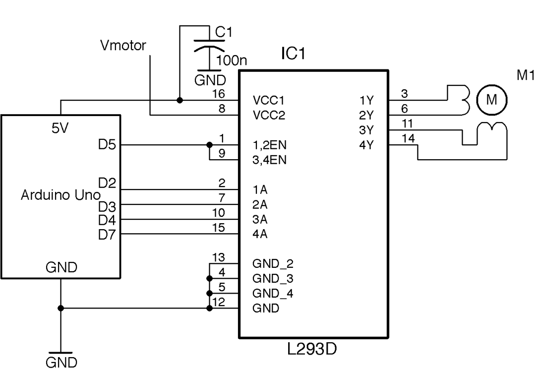
Figure 13-9. Controlling a Bipolar Stepper Motor Using an Arduino Uno
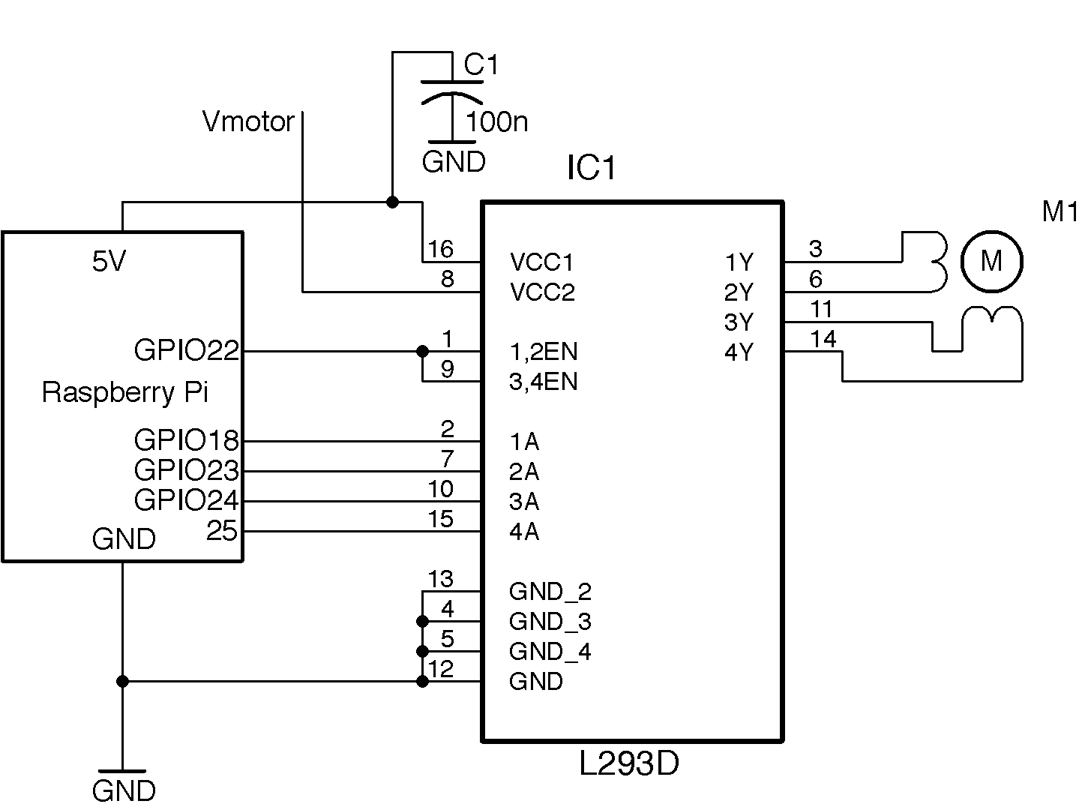
Figure 13-10. Controlling a Bipolar Stepper Motor Using a Raspberry Pi
A push-pull driver is needed for each of the two coils of the stepper motor. The enable pins of the L293D are both tied to a single GPIO pin. Generally the enable pins will be permanently enabled, although they could be used with a high-frequency PWM signal if the stepper motor voltage is below the power-supply voltage.
Arduino software
You can find an Arduino sketch called ch_13_bi_stepper in the downloads for the book (Recipe 10.2):
#include <Stepper.h>constintin1Pin=2;constintin2Pin=3;constintin3Pin=4;constintin4Pin=7;constintenablePin=5;Steppermotor(200,in1Pin,in2Pin,in3Pin,in4Pin);voidsetup(){pinMode(in1Pin,OUTPUT);pinMode(in2Pin,OUTPUT);pinMode(in3Pin,OUTPUT);pinMode(in4Pin,OUTPUT);pinMode(enablePin,OUTPUT);digitalWrite(enablePin,HIGH);Serial.begin(9600);Serial.println("Command letter followed by number");Serial.println("p20 - set the motor speed to 20");Serial.println("f100 - forward 100 steps");Serial.println("r100 - reverse 100 steps");motor.setSpeed(20);}voidloop(){if(Serial.available()){charcommand=Serial.read();intparam=Serial.parseInt();if(command=='p'){motor.setSpeed(param);}elseif(command=='f'){motor.step(param);}elseif(command=='r'){motor.step(-param);}}}
The sketch uses the Stepper library that is included with the Arduino IDE. The library requires you to specify the number of steps as the first parameter in the following line:
Steppermotor(200,in1Pin,in2Pin,in3Pin,in4Pin);
To try out the program, open the Serial Monitor and send commands such as f100, where f is the direction (forward or reverse) and 100 is the number of steps.
Raspberry Pi software
The Raspberry Pi software for driving a bipolar stepper motor can be found in the file ch_13_bi_stepper.py. To download the code for the book see Recipe 10.4.
importRPi.GPIOasGPIOimporttimeGPIO.setmode(GPIO.BCM)in_1_pin=18in_2_pin=23in_3_pin=24in_4_pin=25en_pin=22GPIO.setup(in_1_pin,GPIO.OUT)GPIO.setup(in_2_pin,GPIO.OUT)GPIO.setup(in_3_pin,GPIO.OUT)GPIO.setup(in_4_pin,GPIO.OUT)GPIO.setup(en_pin,GPIO.OUT)GPIO.output(en_pin,True)period=0.02defstep_forward(steps,period):foriinrange(0,steps):set_coils(1,0,0,1)time.sleep(period)set_coils(1,0,1,0)time.sleep(period)set_coils(0,1,1,0)time.sleep(period)set_coils(0,1,0,1)time.sleep(period)defstep_reverse(steps,period):foriinrange(0,steps):set_coils(0,1,0,1)time.sleep(period)set_coils(0,1,1,0)time.sleep(period)set_coils(1,0,1,0)time.sleep(period)set_coils(1,0,0,1)time.sleep(period)defset_coils(in1,in2,in3,in4):GPIO.output(in_1_pin,in1)GPIO.output(in_2_pin,in2)GPIO.output(in_3_pin,in3)GPIO.output(in_4_pin,in4)try:('Command letter followed by number');('p20 - set the inter-step period to 20ms (control speed)');('f100 - forward 100 steps');('r100 - reverse 100 steps');whileTrue:command=input('Enter command: ')parameter_str=command[1:]# from char 1 to endparameter=int(parameter_str)ifcommand[0]=='p':period=parameter/1000.0elifcommand[0]=='f':step_forward(parameter,period)elifcommand[0]=='r':step_reverse(parameter,period)finally:('Cleaning up')GPIO.cleanup()
This code does not use a library, but directly sets the outputs of the push-pull drivers to activate the coils in the right sequence to move the motor forward or backward for the specified number of steps.
Using Python 2?
The preceding code is written for Python 3. If you are running the program as Python 2, then you will need to change the line:
command = input('Enter command: ')
to:
command = raw_input('Enter command: ')
The Python programs in this book are designed to work with Python 2 or Python 3, but the input/raw_input issue is one source of incompatibility between the Python versions that is difficult to code around.
Discussion
Unlike servomotors, stepper motors can rotate continuously—they just do it one step at a time. Typically a stepper motor will have a few tens to a few hundred steps to one full rotation. Moving the stepper motor from one step position to the next involves activating its two coils in a certain pattern.
The L293D lends itself well to experimenting with stepper motors on a breadboard. Figure 13-11 shows an Arduino wired up from the schematic of Figure 13-9. Note that the GND connections are connected inside the chip, so not all ground connections in the schematic need to be made.
See Also
The stepper motor used to test out the preceding examples is from Adafruit, where you will also find a datasheet for the motor).
To use unipolar stepper motors (usually 5-lead), see Recipe 13.6.
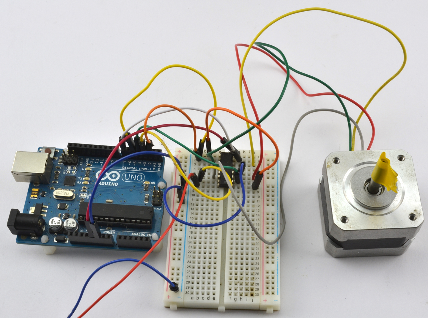
Figure 13-11. Using a Breadboard with an L293D
13.6 Choose a Simpler Stepper Motor
Solution
Unipolar stepper motors are a little easier to use than their bipolar relatives discussed in Recipe 13.6. They do not need a push-pull half-bridge driver, but can be controlled using a Darlington array chip like the ULN2803. Figure 13-12 shows the schematic for using this IC with an Arduino and Figure 13-13 for a Raspberry Pi.
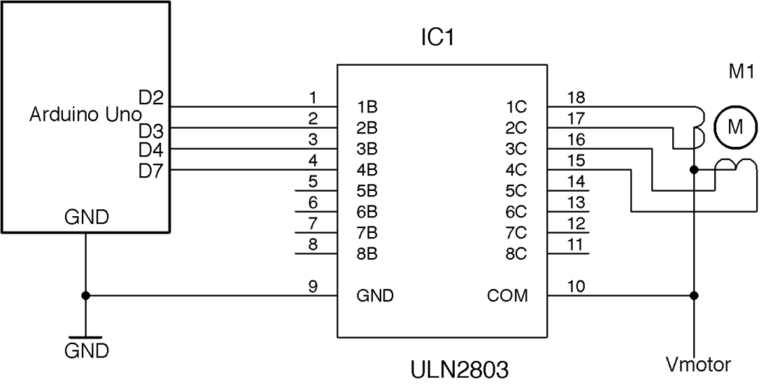
Figure 13-12. Using an ULN2803 to Control a Unipolar Stepper Motor (Arduino)
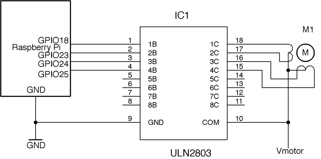
Figure 13-13. Using an ULN2803 to Control a Unipolar Stepper Motor (Raspberry Pi)
The ULN2803 contains eight open-collector Darlington transistors, each capable of sinking about 500mA and so can be used to drive two unipolar stepper motors.
Arduino software
You can find an example Arduino sketch that uses the stepper library in ch_13_uni_stepper with the downloads for the book (see Figure 10-2).
#include <Stepper.h>constintin1Pin=2;constintin2Pin=3;constintin3Pin=4;constintin4Pin=7;Steppermotor(513,in1Pin,in2Pin,in3Pin,in4Pin);voidsetup(){pinMode(in1Pin,OUTPUT);pinMode(in2Pin,OUTPUT);pinMode(in3Pin,OUTPUT);pinMode(in4Pin,OUTPUT);Serial.begin(9600);Serial.println("Command letter followed by number");Serial.println("p20 - set the motor speed to 20");Serial.println("f100 - forward 100 steps");Serial.println("r100 - reverse 100 steps");motor.setSpeed(20);}voidloop(){if(Serial.available()){charcommand=Serial.read();intparam=Serial.parseInt();if(command=='p'){motor.setSpeed(param);}elseif(command=='f'){motor.step(param);}elseif(command=='r'){motor.step(-param);}}}
The sketch is pretty much the same as that of Recipe 13.5, but in this case there is no enable pin possible. See the sketch in Recipe 13.5 for a description of the code.
Raspberry Pi software
The Raspberry Pi version of the software can be found in the program ch_13_uni_stepper.py. It is identical to that of Recipe 13.5 but with the driver-enable feature removed:
importRPi.GPIOasGPIOimporttimeGPIO.setmode(GPIO.BCM)in_1_pin=18in_2_pin=23in_3_pin=24in_4_pin=25GPIO.setup(in_1_pin,GPIO.OUT)GPIO.setup(in_2_pin,GPIO.OUT)GPIO.setup(in_3_pin,GPIO.OUT)GPIO.setup(in_4_pin,GPIO.OUT)period=0.02defstep_forward(steps,period):foriinrange(0,steps):set_coils(1,0,0,1)time.sleep(period)set_coils(1,0,1,0)time.sleep(period)set_coils(0,1,1,0)time.sleep(period)set_coils(0,1,0,1)time.sleep(period)defstep_reverse(steps,period):foriinrange(0,steps):set_coils(0,1,0,1)time.sleep(period)set_coils(0,1,1,0)time.sleep(period)set_coils(1,0,1,0)time.sleep(period)set_coils(1,0,0,1)time.sleep(period)defset_coils(in1,in2,in3,in4):GPIO.output(in_1_pin,in1)GPIO.output(in_2_pin,in2)GPIO.output(in_3_pin,in3)GPIO.output(in_4_pin,in4)try:('Command letter followed by number');('p20 - set the inter-step period to 20ms (control speed)');('f100 - forward 100 steps');('r100 - reverse 100 steps');whileTrue:command=raw_input('Enter command: ')parameter_str=command[1:]# from char 1 to endparameter=int(parameter_str)ifcommand[0]=='p':period=parameter/1000.0elifcommand[0]=='f':step_forward(parameter,period)elifcommand[0]=='r':step_reverse(parameter,period)finally:('Cleaning up')GPIO.cleanup()
See Also
The unipolar stepper motor that I used to validate these recipes is this Adafruit model: https://www.adafruit.com/product/858.
To use bipolar stepper motors, see Recipe 13.6.
The ULN2803 datasheet can be found here: http://www.ti.com/lit/ds/symlink/uln2803a.pdf.