Table of Contents for
Electronics Cookbook
 Electronics Cookbook
Published by
O'Reilly Media, Inc., 2017
Electronics Cookbook
Published by
O'Reilly Media, Inc., 2017
- Cover
- nav
- Electronics Cookbook
- Electronics Cookbook
- Preface
- Theory
- Resistors
- Capacitors and Inductors
- Diodes
- Transistors and Integrated Circuits
- Switches and Relays
- Power Supplies
- Batteries
- Solar Power
- Arduino and Raspberry Pi
- Switching
- Sensors
- Motors
- LEDs and Displays
- Digital ICs
- Analog
- Operational Amplifiers
- Audio
- Radio Frequency
- Construction
- Tools
- Parts and Suppliers
- Arduino Pinouts
- Raspberry Pi Pinouts
- Units and Prefixes
- Index
- About the Author
- Colophon
Chapter 8. Batteries
8.0 Introduction
In Chapter 7 you learned about various ways of supplying low-voltage DC to your electronics designs from AC. In this chapter you will learn how to use various types of batteries and photovoltaic solar cells.
8.1 Estimating Battery Life
Solution
The capacity of a battery is specified in Ah (ampere hours) or mAh (milliampere hours). To calculate how many hours your battery will last, you need to divide this number by the current consumption of your project in A or mA.
For example, a 9V PP3 rechargeable battery typically has a capacity of about 200mAh. If you were to connect an LED with a suitable series resistor that limited the current to 20mA, the battery should be good for about:

Discussion
The estimate of time you get using the preceding calculation is very much an estimate and all sorts of factors such as the age of the battery, the temperature, and the current will affect the actual battery life.
If you are using a number of batteries in serial (e.g., in a battery holder that contains 4xAA batteries), then you do not get to multiply the battery life by 4, because the same current will be flowing out of each battery (Figure 8-1).
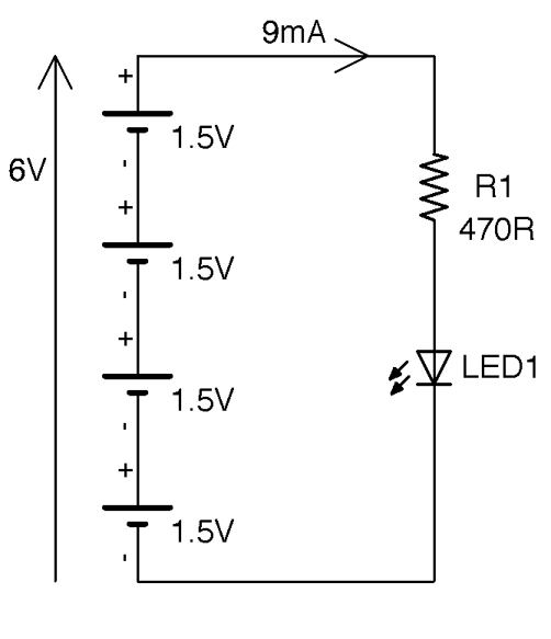
Figure 8-1. Batteries in Series
From Kirchhoff’s Current Law (Recipe 1.4) we know the current flowing past any point in the circuit will be the same. Assuming an LED with a forward voltage of 1.8V the current will be around 9mA. Even though there is more than one battery cell, each cell will have 9mA flowing through it. A typical AA battery has a capacity of around 2000mAh and so we could expect this circuit to run for:

It is best to avoid putting batteries in parallel because none of the cells in the battery will be at exactly the same voltage and when you connect them together, the first thing that will happen is their voltages will equalize with the higher voltage batteries discharging into the lower voltage batteries. If the batteries are rechargeable, you may be okay if the voltage difference is very small, but for nonrechargeable batteries, this charging process can heat the batteries and be dangerous.
Batteries all have an internal resistance, very similar to the ESR of a capacitor (Recipe 3.2). This will cause heating as the battery discharges, which is why you cannot use a small 200mAh battery to supply 10A for 72 seconds. The internal resistance of the battery will both limit the current and cause the battery to heat up. Small batteries tend to have higher internal resistance than big batteries.
Most nonrechargeable batteries bought from a component supplier will specify the maximum continuous discharge current.
See Also
For information on choosing between different types of rechargeable batteries see Recipe 8.3 and for nonrechargeable batteries see Recipe 8.2.
To measure the current used by your project using a multimeter, see Recipe 21.4.
8.2 Selecting a Nonrechargeable Battery
Solution
Decide what your minimum battery life for the product should be and calculate the capacity of the battery you need in mAh, then use Table 8-1 to select a battery.
If you need more volts than a single battery cell provides, then place several of the cells in series in a battery holder.
| Battery Type | Approx. Capacity (mAh) | Voltage (V) |
|---|---|---|
| Lithium Button Cell (e.g., CR2032) | 200 | 3 |
| Alkaline PP3 Battery | 500 | 9 |
| Lithium PP3 | 1,200 | 9 |
| AAA Alkaline | 800 | 1.5 |
| AA Alkaline | 2,000 | 1.5 |
| C Alkaline | 6,000 | 1.5 |
| D Alkaline | 15,000 | 1.5 |
Discussion
Higher capacity nonrechargeable batteries are expensive and so C and D cells are found less and less often in favor of rechargeable LiPo battery packs (see Recipe 8.3).
You should also be wary of using exotic or unusual batteries. It’s generally a good idea to stick to universally available batteries like AA cells unless you need something smaller in which case AAA batteries will do.
Battery holders such as the 4 x AA battery holder shown in Figure 8-2 are readily available to hold 1, 2, 3, 4, 6, and 8 AA cells to make a battery pack capable of supplying 1.5, 3, 4.5, 6, 9, and 12V, respectively.
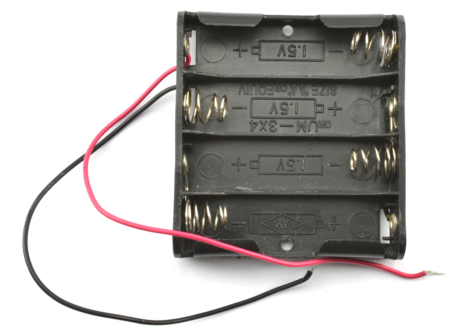
Figure 8-2. A 4 x AA Battery Pack
Perfect batteries would allow you to draw as large a current as you want. However, in reality batteries have a small resistance that will cause heating as the battery discharges. The higher the current the greater the heat produced. Smaller capacity batteries have a lower maximum discharge rate than larger batteries.
See Also
For information on rechargeable batteries, see Recipe 8.2.
8.3 Selecting a Rechargeable Battery
Solution
Decide how long you would like your project to operate between charges and use Table 8-2 to choose a battery.
| Battery Type | Approx. Capacity (mAh) | Voltage (V) |
|---|---|---|
| NiMh button cell pack | 80 | 2.4-3.6 |
| NiMh AAA cell | 750 | 1.25 |
| NiMh AA cell | 2,000 | 1.25 |
| LC18650 LiPo cell | 2,000 to 8,000 | 3.7 |
| LiPo Flat cell | 50 to 8,000 | 3.7 |
| Sealed lead acid (SLA) | 600, 8,000 | 6 or 12 |
Discussion
LiPo (lithium polymer) and the closely related lithium ion cells are the lightest and also now as cheap per mAh as older technologies such as MiMh, but they require care when charging and discharging or they can catch fire (see Recipe 8.6).
You will still find NiMh batteries in products like electric toothbrushes. They are heavier than LiPos of the same capacity but are easy to charge (see Recipe 8.4).
SLA batteries (sealed lead acid) are even heavier than NiMh cells but cope well with trickle charging and last for years. However, their use is on the decline in favor of lighter-weight LiPo batteries.
Many rechargeable batteries will specify safe charge and discharge rates in units of C. This refers to a ration of the battery’s nominal capacity. So, a 1Ah battery that says it can be discharged at 5C is capable of supplying 5A (5 x 1A). If the maximum charge current is specified as 2C the battery can be charged at 2A.
See Also
For a similar recipe but for nonrechargeable batteries, see Recipe 8.2.
8.4 Trickle Charging
Problem
You want to charge a NiMh or SLA battery while it’s connected to your circuit and you don’t need to charge it quickly.
Don’t Trickle Charge LiPo Batteries Like This
Note that LiPo batteries should not be trickle charged in this way. Instead, see Recipe 8.6 on charging LiPo batteries.
Solution
Trickle charge the battery from a power supply using a resistor to limit the current. If you don’t know how the power supply works, then also include a diode in the circuit to prevent damage to the power supply when the power is turned off. Figure 8-3 shows the schematic for charging a 6V battery from a 12V supply.
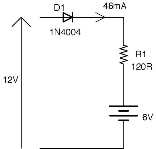
Figure 8-3. Trickle Charging
Discussion
A battery’s datasheet will specify the charging current to use for fast charging and in this case slow trickle charging in terms of C, where in this case, C is not capacitance but rather the capacity of the battery in mAh. So the datasheet for an AA rechargeable battery might say that it should be trickle charged at C/10 mA, meaning that if the battery is a 2000mAh AA cell, it can be trickle charged at 2000/10 = 200mA indefinitely without damaging the battery. Charging below 200mA will still result in the battery being charged, and in situations like battery backup (Recipe 8.5) charging at C/50 (40mA) is probably a good compromise between charging speed and power consumption of the circuit.
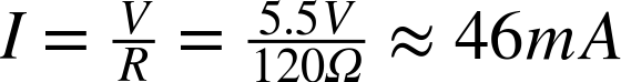
To charge at 40mA we just need to set the value of R. The voltage across R will be 12V – 6V – 0.5V = 5.5V. We know that the current is 40mA, so we can calculate R using Ohm’s Law as:

Using the standard resistor value of 120Ω will result in a slightly higher current of:
We also need to make sure the resistor has a sufficient power rating, which we can calculate as:

So, a ¼W resistor is probably OK, but ½W would not get as hot.
An alternative to using a resistor to limit the current is to use Recipe 7.7 to provide a constant charging current. This design is more complex and expensive, but will cope better with variations in the input voltage and the battery’s voltage changing as it charges.
See Also
Charging from a photovoltaic solar cell is very similar to trickle charging (see Recipe 9.1).
8.5 Automatic Battery Backup
Solution
Use a battery of slightly lower voltage than the power adapter–supplied voltage and a pair of diodes in the arrangement shown in Figure 8-4.
The diodes ensure that the output is supplied from either the battery or the power supply, whichever has the higher voltage. Since you want the power supply to be providing the voltage most of the time, arrange for it to be a volt or more higher than the battery voltage (remember the battery voltage will drop as it discharges). In Figure 8-4, when the power supply is producing 10V, D1 will be forward-biased (conducting) and D2 reverse-biased. This reverse-biasing of D2 prevents any accidental charging of the battery (which may not be rechargeable). If the power supply were to turn off, D2 becomes forward-biased, providing the output voltage and D1 would become reverse-biased preventing any possible flow of current into the power supply that could damage it, especially if it is an SMPS design (Recipe 7.8).
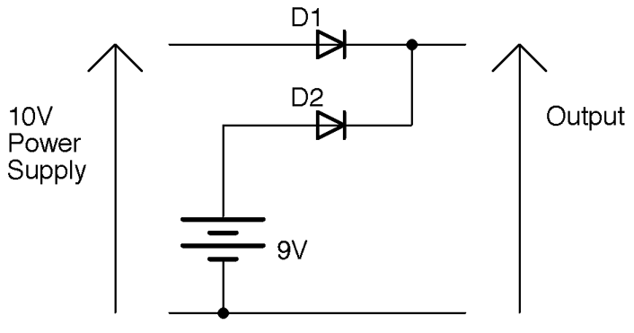
Figure 8-4. Automatic Battery Backup
Discussion
When selecting a diode type for D1 and D2, you need to make sure it can handle the current that the output needs to provide. Although in most cases regular diodes like the 1N4xxx series are just fine, they will result in a forward-voltage drop of at least 0.5V. You can reduce this voltage drop by using Schottky diodes (Recipe 4.2).
The circuit of Figure 8-4 will work just fine for rechargeable or nonrechargeable batteries, but it will not charge the batteries. If using rechargeable batteries, you can modify the circuit slightly so that the power supply trickle charges the battery and supplies the output. Figure 8-5 shows the schematic for this. See Recipe 8.4 for the calculation for the charging resistor.
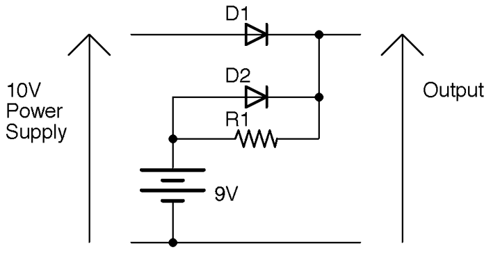
Figure 8-5. Trickle Charge and Battery Backup
Now when the power supply is in charge some of the current from D1 will flow through R1 and charge the battery (D2 is reverse-biased and can effectively be ignored). When the power supply is off (0V) D2 becomes forward-biased and supplies power to the output. At this time, R1 becomes irrelevant as D2 will be conducting.
See Also
See Recipe 4.2 for help selecting the right diode.
For the basics of what diodes do, see Recipe 4.1.
8.6 Charging LiPo Batteries
Solution
Use a LiPo-charging IC designed specifically for the purpose of charging LiPo batteries. The schematic of Figure 8-6 is an example design using the MCP73831 IC.
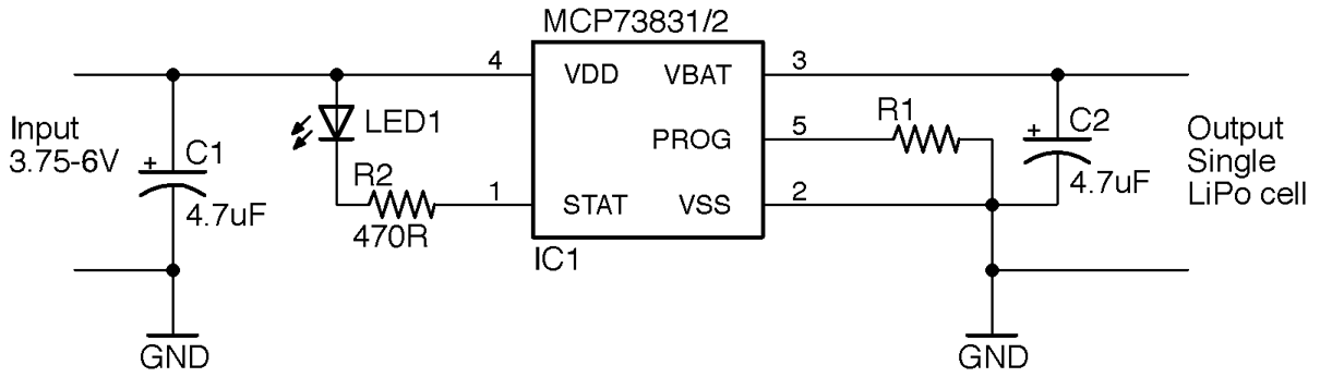
Figure 8-6. Charging a LiPo Battery
Many consumer electronics use LiPo batteries (often charged from a USB connection) with chips like the MCP73831 and many are low cost (less than $1) and include all sorts of advanced features that make sure the LiPo cell is charged safely.
The MCP73831 only needs two capacitors and a resistor to make a complete LiPo-charging circuit. The LED and R2 provide a status indicator that shows that the battery is charging and can be omitted if you don’t need it.
The chip will automatically control the charge current, turning it to a safe trickle charge when the cell is fully charged. However, you can set the maximum charge current in amps (consult the datasheet for the LiPo cell that you plan to use) by means of R1, using the formula:
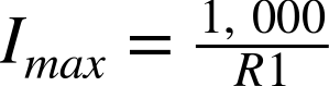
So, to charge at 500mA (the maximum allowed by the chip anyway) set R1 to 2kΩ.
As an alternative to using a design of your own to charge a LiPo cell, you can also buy ready-made LiPo charge modules such as the Adafruit 1905 and Sparkfun PRT-10217 (both use the MCP73831).
Discussion
LiPo batteries have made the news in recent years because they will catch fire if abused. Using a charger chip like the MCP73831 in your circuits will help ensure your design is safe and reliable. For extra safety, you can add a thermal fuse (Recipe 7.16) to the supply to the charging circuit.
If you are looking for a lower-tech solution then consider using a NiMh or SLA battery instead.
Unlike NiMh or SLA batteries, LiPo batteries are not suited for charging in parallel. Each cell effectively has to be charged independently using special hardware. If your project cannot operate directly from the 3.7V of a LiPo cell and needs a bit more voltage, then it is generally easier to use a boost converter (Recipe 7.9) to generate the voltage you need.
See Also
You can find the datasheet for the MCP73831 here: http://bit.ly/2n2XUPP.
8.7 Get Every Drop of Power with the Joule Thief
Solution
The novelty circuit known as a joule thief allows you to power an LED from an alkaline AA cell even when its voltage drops to around 0.6V.
A joule thief is actually a small self-oscillating boost converter (see Recipe 7.9) that requires just a transistor, resistor, and homemade transformer to drive an LED from a single 1.5V battery, even when the battery voltage drops as low as 0.6V. The circuit is shown in Figure 8-7.
The circuit is very similar in operation to the self-oscillating boost converter used in Recipe 7.15 except that the secondary winding has the same number of turns as the primary and is connected back to the base via a resistor rather than using parasitic (from the winding) capacitance.
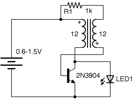
Figure 8-7. Joule Thief Schematic
Discussion
Figure 8-8 shows a joule thief. This circuit is interesting because it is fun to make one and see just how long an AA battery can power an LED.
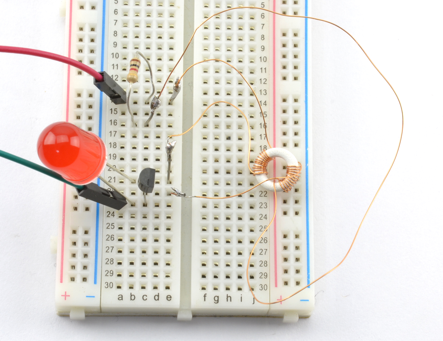
Figure 8-8. A Joule Thief on a Breadboard
I made my transformer by winding 12 turns of 30 AWG (34 SWG) enameled copper wire, for each winding, around a tiny toroidal ferrite core. In reality, more or less of any ferrite core and even plastic insulated wire will work just fine.
The supply generates pulsed DC at a frequency of about 50kHz (depending on the transformer).
See Also
For more practical boost converters, see Recipe 7.9.
Recipe 7.15 uses a very similar circuit to this recipe.
For information on wire gauges, see Recipe 2.10.