Table of Contents for
Electronics Cookbook
 Electronics Cookbook
Published by
O'Reilly Media, Inc., 2017
Electronics Cookbook
Published by
O'Reilly Media, Inc., 2017
- Cover
- nav
- Electronics Cookbook
- Electronics Cookbook
- Preface
- Theory
- Resistors
- Capacitors and Inductors
- Diodes
- Transistors and Integrated Circuits
- Switches and Relays
- Power Supplies
- Batteries
- Solar Power
- Arduino and Raspberry Pi
- Switching
- Sensors
- Motors
- LEDs and Displays
- Digital ICs
- Analog
- Operational Amplifiers
- Audio
- Radio Frequency
- Construction
- Tools
- Parts and Suppliers
- Arduino Pinouts
- Raspberry Pi Pinouts
- Units and Prefixes
- Index
- About the Author
- Colophon
Chapter 6. Switches and Relays
6.0 Introduction
Mechanical switches allow the flow of current to be turned on and off by flipping a toggle from one position to another or by pressing a button. They are so simple that they require little in the way of explanation other than to describe the various types of switches available and to highlight their limitations.
Relays long predate transistors as a means of using a small current to switch to a much bigger one. However, their flexibility and separation of the control side from the switching side mean that they are still in use today.
6.1 Switch Electricity Mechanically
Solution
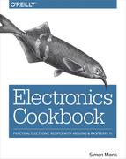
Switches generally work by mechanically bringing together two metal contacts. Figure 6-1 shows how this might work.
When the push button is pressed, it presses the sprung metal contact at the top to the fixed contact in the base of the switch.
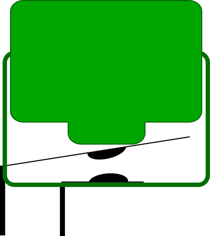
Figure 6-1. The Mechanical Construction of a Push Switch
Discussion
There are several things that can make switching less straightforward than you might expect:
- When switching high voltages there may be arcing (sparking) just before the two contacts connect and even more so when they disconnect. This causes heat and can damage the contacts.
- When switching high currents at any voltage, there is a danger of the contacts spot-welding themselves together as the contact is made, preventing the switch from turning off again.
- A continuous high current through a switch will cause the contacts (which have a small resistance) to heat up, shortening the life of the switch.
- The contacts often bounce, making and releasing contact a few times in very rapid succession before settling. This can cause a problem when used with software that toggles something on and off. In Recipe 12.1 you will see how a switch press can be debounced.
For these reasons switches have a maximum voltage and current, and there are often separate maximums for switching AC and DC.
See Also
For a discussion of the various types of switch, see Recipe 6.2.
6.2 Know Your Switches
Solution
Figure 6-2 shows a selection of switches.
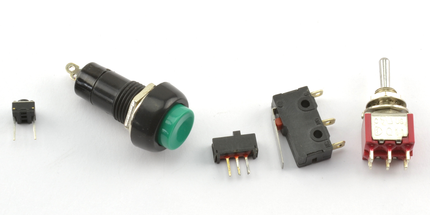
Figure 6-2. A Selection of Switches
The switches from left to right are:
- A tactile push switch. This is probably the most commonly used switch in commercial products. They are low-cost circuit board–mountable push switches.
- A panel mount push switch. These are good for creating one-off projects as they can just be mounted into a hole drilled into an enclosure.
- A slide switch. Moving the slider connects the center contact to either the left or right pins.
- Microswitch. The hinged lever and mounting holes make it easy to attach to a mechanical assembly. Because they have a hinged lever, they do not need much force to operate. These switches are durable and reliable and often built into microwave ovens to turn off the power if the door is opened.
- A toggle switch. These are the classic on/off switches.
Discussion
If you are designing a project, then you are probably most likely to be using a microcontroller of some sort, in which case a simple push switch is all that is required. Even if you have a situation where you might want to use a switch to select between two options, chances are you would use a pair of push switches and some feedback as to which is selected in a display.
Slide and toggle switches have mostly been relegated to the role of switching power on and off to the project, although you will occasionally find them on circuit boards as “selector” switches.
Toggles (and other switches) are available in many different switching configurations. Some of those described include DPDT, SPDT, SPST, and SPST. These letters stand for:
- D—Double
- S—Single
- P—Pole
- T—Throw
A DPDT switch is double pole, double throw. The word pole refers to the number of separate switch elements that are controlled from the one mechanical lever. So, a double-pole switch can switch two things on and off together. A single-throw switch can only open or close a contact (or two contacts if it is a double pole). However, a double-throw switch can make the common contact be connected to one of two other contacts. Figure 6-3 shows some of these configurations.
As seen in Figure 6-3 when drawing a schematic with a double-pole switch, it is common to draw the switch as two switches (S1a and S1b) and connect them with a dotted line to show that they are linked mechanically.
The matter is further complicated because you can have three poles or more on a switch, and double-throw switches are sometimes sprung, and do not stay in one or both of these positions. They may also have a center-off position where the common contact is not connected to any other contact.
Another kind of switch that you may encounter is the rotary switch. This has a knob that can be set to a number of positions. If you have a multimeter, then this is the kind of switch that you will use to select the range. Such switches are not often used. Rotary encoders coupled with a microcontroller (Recipe 12.2) are the more modern way of making a selection using a control knob that you turn.
Figure 6-3. Switch Poles and Throws
See Also
To use switches with an Arduino or Raspberry Pi, see Recipe 12.1.
6.3 Switching Using Magnetism
Solution
A reed switch is made up of a pair of contacts running parallel to each other that are close but not touching. The contacts are enclosed in a glass capsule and when a magnet is brought close to the contacts they are drawn together, closing the switch.
Figure 6-4 shows a reed switch with and without a magnet next to it.
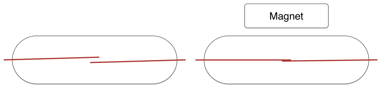
Figure 6-4. Switch Poles and Throws
Discussion
Reed switches are often found in intruder alarms on doors and windows. A fixed magnet is attached to the door and the reed switch to the door frame. When the door is opened, the magnet moves away from the reed switch, triggering the alarm.
See Also
Reed switches are also found in reed relays but are rarely used these days.
6.4 Rediscover Relays
Solution
An electromechanical relay has two parts, a coil that acts as an electromagnet and switch contacts that close when the coil is energized. Figure 6-5 shows a relay, along with the pinout of the relay and a photo of an actual relay.
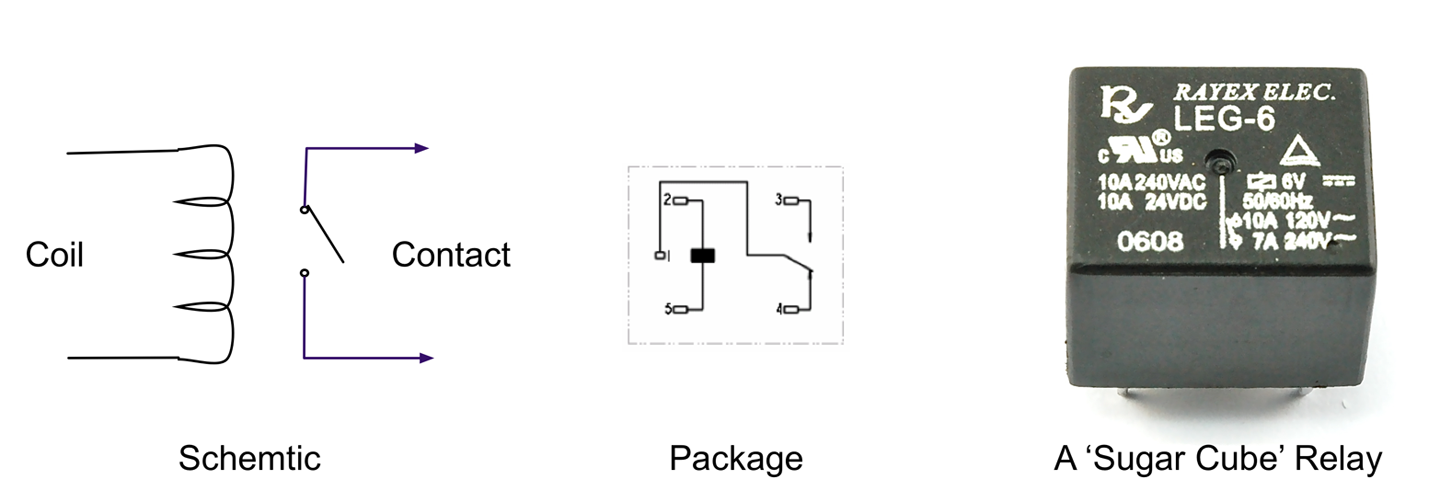
Figure 6-5. A Relay
Discussion
Although somewhat old-fashioned, relays are still in use today. They are equally happy switching AC or DC and are easily interfaced to a microcontroller.
If you take a relay apart, you will probably see something like Figure 6-6.
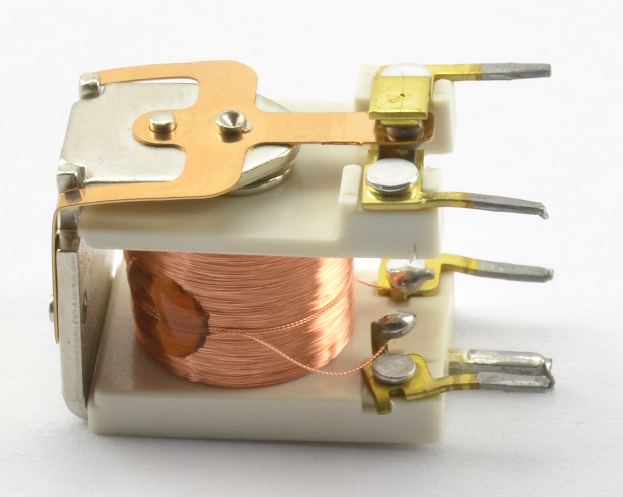
Figure 6-6. Inside a Relay
Here you can clearly see the coil that forms the electromagnet that when energized will move the contacts seen at the top.
The electromagnet of a relay is a big coil of wire and when released will produce a voltage spike that should be snubbed using a diode (see Recipe 11.9).
See Also
See Recipe 11.9 for information on using a relay with an Arduino or Raspberry Pi.
Today SSRs are often used in place of electromechanical relays (see Recipe 11.10).