Table of Contents for
Electronics Cookbook
 Electronics Cookbook
Published by
O'Reilly Media, Inc., 2017
Electronics Cookbook
Published by
O'Reilly Media, Inc., 2017
- Cover
- nav
- Electronics Cookbook
- Electronics Cookbook
- Preface
- Theory
- Resistors
- Capacitors and Inductors
- Diodes
- Transistors and Integrated Circuits
- Switches and Relays
- Power Supplies
- Batteries
- Solar Power
- Arduino and Raspberry Pi
- Switching
- Sensors
- Motors
- LEDs and Displays
- Digital ICs
- Analog
- Operational Amplifiers
- Audio
- Radio Frequency
- Construction
- Tools
- Parts and Suppliers
- Arduino Pinouts
- Raspberry Pi Pinouts
- Units and Prefixes
- Index
- About the Author
- Colophon
Chapter 11. Switching
11.0 Introduction
Most modern electronics are concerned with switching things. Microcontrollers and any other digital logic device use transistors as switches. Taking this a step further, devices like Arduino and Raspberry Pi can switch external devices, perhaps controlling lighting or power to a heater.
The recipes in this chapter are all concerned with using transistors and other devices to switch. This includes some recipes to extend the switching power of an Arduino and Raspberry Pi.
11.1 Switch More Power than Your Pi or Arduino Can Handle
Solution
Use a transistor in a common-emitter arrangement as a “low-side” switch with a resistor to limit the base current. Figure 11-1 shows the schematic for this circuit, that, along with Recipe 11.2, you will use time and time again in your designs.
This type of switching is called “low-side” switching because the transistor acts as a switch between the low voltage of GND and the load.
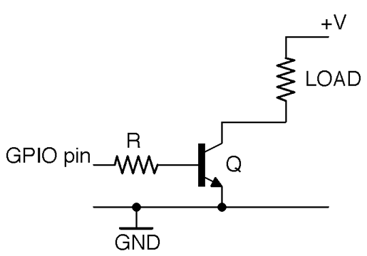
Figure 11-1. Using a Transistor as a Switch
Discussion
The resistor R makes sure that the current drawn from the GPIO pin does not exceed the current limit of the pin (40mA for Arduino and 16mA for Raspberry Pi; see also Recipe 10.7). It also protects the transistor from too much base current flowing. This protective role must be balanced against the limited gain of a bipolar transistor, which may only be 100 or less. So if you are planning to use the transistor to switch a current of 1A, you could reasonably expect a base current of 10mA. This means that for this 1A load, you need to choose a value of R that gives a base current somewhere between the available current of the GPIO and 10mA.
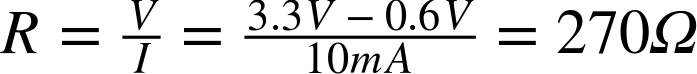
Aiming for a 10mA base current (if you are using a 5V GPIO pin and assume that the base-emitter voltage is a fairly constant 0.6V) you can calculate the value of R as:

Applying the same calculation for a 3.3V GPIO pin you get:
The two connections from this circuit to an Arduino or Raspberry Pi are the GND connection and the GPIO pin. The positive voltage supply to the load is entirely separate from the Raspberry Pi or Arduino. This means that you are not restricted to switching the logic level of the Arduino or Pi (3.3V or 5V) but can switch up to the maximum voltage that the transistor is capable of switching.
Having said that, you will often use the positive voltage supply of an Arduino or Raspberry Pi for the convenience of having a single voltage source.
See Also
For a discussion of bipolar transistors, see Recipe 5.1.
GPIO ports and their output logic are described in Recipe 10.7.
You will find an example of switching with a transistor using an Arduino in Recipe 11.6 and for a Raspberry Pi in Recipe 11.7.
For switching using a MOSFET, see Recipe 11.3.
11.2 Switch Power On the High Side
Solution
The arrangement of Figure 11-1 is called low-side switching because the switching takes place on the lower voltage side; that is, to GND rather than from the positive supply. This means that whatever is being switched has to have a connection to the positive supply voltage.
One approach to high-side switching is to simply rearrange Figure 11-1 a little as shown in Figure 11-2.
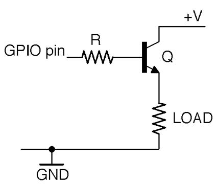
Figure 11-2. High-side Switching with an NPN BJT (Restricted Switching Range)
The circuit of Figure 11-2 cannot switch voltages (+V) greater than the GPIO pin’s voltage less half a volt.
A transistor in this arrangement is called an emitter follower (Recipe 16.4) because the emitter will generally be about 0.6V less than the base. This means that we can use this arrangement for high-side switching but only so long as the voltage at the GPIO pin is less than +V.
In short, the circuit of Figure 11-2 is only useful for switch loads where one end of the load must be connected to ground and the other does not need a supply voltage that is greater than the control voltage of the GPIO pin.
Discussion
If you need to switch a higher voltage (perhaps 12V) you might be tempted to consider an alternative to Figure 11-2 that uses a PNP transistor rather than an NPN transistor as shown in Figure 11-3.
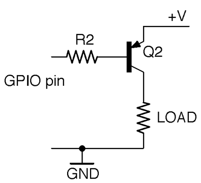
Figure 11-3. High-side Switching with a PNP BJT (Defective)
This circuit is defective because Q2 will turn on with a base current when its base is about 0.6V lower than +V. So, if you were trying to switch a 12V load from 5V logic, the base voltage would always be over 0.6V and enough base current would flow to keep the transistor on whether the GPIO pin was at 5V or GND.
If you need to be able to switch voltages of V+ that are greater than the 5V of your Arduino or 3.3V of your Raspberry Pi and you don’t want to use the tristate logic trick, then you will need to use the arrangement shown in Figure 11-4.
This uses a separate NPN transistor Q1 to control the base current to Q2 giving a full switching range.

Figure 11-4. High-side Switching with an NPN BJT Driving a PNP BJT
Low-side switching (Recipe 11.1) is the most common and simplest arrangement, and unless you have a good reason such as the need for one end of the load to be connected to ground, you should use low-side switching.
See Also
For a discussion of NPN and PNP bipolar transistors, see Recipe 5.1.
GPIO ports and their output logic are described in Recipe 10.7.
You will find an example of switching with a transistor using an Arduino in Recipe 11.6 and for a Raspberry Pi in Recipe 11.7.
For switching using a MOSFET, see Recipe 11.3.
11.3 Switch Much More Power
Solution
You can use a MOSFET as an electronic switch. Use the transistor in a common-source arrangement. Figure 11-5 shows the schematic for this circuit. Along with Recipe 11.1, you will find yourself using this circuit a lot.
This type of switching is called “low-side” switching because the transistor acts as a switch between the low voltage of GND and the load.
If the GPIO pin is high (3.3V or 5V) and exceeds the gate-threshold voltage of the MOSFET, the MOSFET will turn on, allowing current to flow from +V through the load to GND.
Choosing Logic-level MOSFETs
When using MOSFETs as switches controlled by GPIO pins you should look for devices described as logic level. These have a low-threshold voltage (generally 2V or less), whereas MOSFETs not described as logic-level may well have gate-threshold voltages of 4V to 7V.
Logic-level versions of regular MOSFETs often have the same name, but an L after the name. For example, the FQP30N06L is the logic-level version of the FQP30N06.
Low-power MOSFETs like the 2N7000 generally have pretty low gate-threshold voltages anyway and are fine with 3.3V logic without having the L designation.
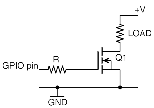
Figure 11-5. Switching with an N-Channel Enhancement-mode MOSFET
Discussion
You may be wondering why the gate resistor R is needed. In reality for most MOSFETS in most relatively low-current applications, it isn’t needed at all and you can just connect the GPIO pin directly to the gate.
However, the MOSFET’s gate appears to the GPIO pin as a capacitor that will be charged and discharged as the GPIO pin goes high and low. So, if you are switching the MOSFET at high speed (say PWM at a high frequency) or the MOSFETs’ gate capacitance is high (it increases with load current) then the maximum rated output current of the GPIO pin may be exceeded and the transistors inside the GPIO output could overheat. In any case, resistors are cheap and it’s good practice to include one.
In Figure 11-5 the gate of the MOSFET is floating. If it is connected to a GPIO set to be an output, then the MOSFET will be in a stable state, but there are several reasons why this might not be the case:
- The program to control the GPIO might not be running yet on your Raspberry Pi, in which case the GPIO will be a floating input.
- The control hardware may be detachable from the Arduino or Raspberry Pi GPIO pin while still retaining its positive supply.
- If the gate is left floating the load is likely to turn itself on and off in response to electrical noise. This is just like the experience of a floating input in an Arduino as described in Recipe 10.10.
To prevent this unwanted behavior, you can just add a pull-down resistor to keep the gate low unless the GPIO pin is actively driving the gate (see Figure 11-6). This resistor should have a resistance of perhaps 10 times that of the gate-protection resistor (R1) to prevent the effective voltage divider (Recipe 2.6) formed by R1 and R2 from reducing the gate voltage by any significant amount.
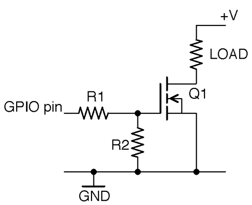
Figure 11-6. Preventing a Floating Gate from Causing Problems
See Also
For a discussion of MOSFETs, see Recipe 5.3.
GPIO ports and their output logic are described in Recipe 10.7.
You will find an example of switching with a MOSFET using an Arduino in Recipe 11.6 and for a Raspberry Pi in Recipe 11.7.
For switching using a BJT, see Recipe 11.1.
11.4 Switch Much More Power on the High Side
Solution
The problems with high-side switching using a MOSFET are similar to those of Recipe 11.2. However, whereas in Recipe 11.2 it was okay to use an emitter-follower configuration or PNP transistor on its own, the need for a gate-source voltage above the threshold voltage to turn the MOSFET on means that the switchable range is reduced by at least the threshold voltage, making the circuit unsuitable for most applications.
So, for high-side switching there is little alternative to using the circuit of Figure 11-7.
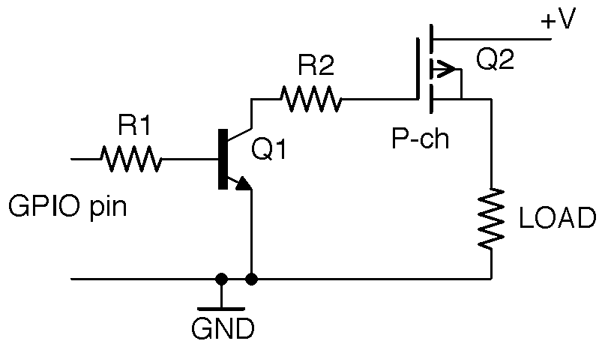
Figure 11-7. High-side Switching with a P-Channel MOSFET and BJT
Discussion
By using a BJT rather than a MOSFET for Q1, there will always be enough leakage current through Q1 to keep the gate of Q2 low when the control pin is left floating.
See Also
For a discussion of MOSFETs, see Recipe 5.3.
GPIO ports and their output logic are described in Recipe 10.7.
You will find an example of switching with a MOSFET using an Arduino in Recipe 11.6 and for a Raspberry Pi in Recipe 11.7.
11.5 Choose Between a BJT and MOSFET
Solution
Use Table 11-1 to help you decide which NPN BJT or N-Channel MOSFET to use in low-side switching.
| Technology | Examples | |
|---|---|---|
| under 100mA | BJT or MOSFET | 2N3904 or 2N7000 |
| under 200mA | MOSFET | 2N7000 |
| under 500mA | Darlington or MOSFET | MPSA14 or FQP30N06L |
| under 3A | Darlington or MOSFET | TIP120 or FQP30N06L |
| under 20A | MOSFET | FQP30N06L |
While any of these transistors would technically work, over time you’ll find that you return to a few of your favorite transistors.
Discussion
When it comes to switching small loads (say under 100mA) a small BJT (like the 2N3904) and a small MOSFET (like the 2N7000) are pretty much interchangeable. In fact, their pinouts mean that they are in the same transistor package and are pin-compatible.
Above 100mA but below 200mA I would usually select a 2N7000 because its low on-resistance means that it will not get as hot as a BJT.
Between 200mA and 500mA, I would either use a Darlington MPSA14 to save space over a FQP30N06L MOSFET (in a larger package), but only if I could afford the 1.5V or more voltage drop of the MPSA14.
Between 500mA and 3A you are definitely in large-transistor territory in a TO-220 package. If you can afford the voltage drop of a Darlington then the TIP120 is a good choice; otherwise, a FQP30N06L will serve you well.
For powers over 3A use a FQP30N06L with a heatsink.
See Also
See also Recipe 5.5.
2N3904 datasheet: https://www.sparkfun.com/datasheets/Components/2N3904.pdf
2N7000 datasheet: https://www.fairchildsemi.com/datasheets/2N/2N7000.pdf
MPSA14 datasheet: http://www.farnell.com/datasheets/43685.pdf
FQP30N06L datasheet: https://www.fairchildsemi.com/datasheets/FQ/FQP30N06L.pdf
TIP120 datasheet: https://www.fairchildsemi.com/datasheets/TI/TIP122.pdf
11.6 Switch with Arduino
Solution
If you have a 5V Arduino like the Arduino Uno, then each GPIO pin can switch a maximum of 5V at 40mA. To increase either the voltage or the current, you need to use a transistor. The principles and even the breadboard layouts are much the same whether you use a BJT or a MOSFET. See Recipe 11.5 for the relative merits of each technology.
Figure 11-8 shows the schematic for this.
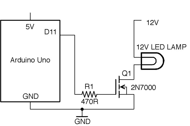
Figure 11-8. Schematic for an Arduino Controlling a 12V Load
NOT for AC
This circuit is for low-voltage DC only. Do not try and use it to switch AC. To do so would not work and would also be very dangerous.
Discussion
You can build this circuit on a breadboard to experiment. Figure 11-9 shows the breadboard layout for the project using a 2N7000, which is good for 200mA (2.4W). If you prefer, you could use a 2N3904 or an MPSA14 with exactly the same breadboard layout.
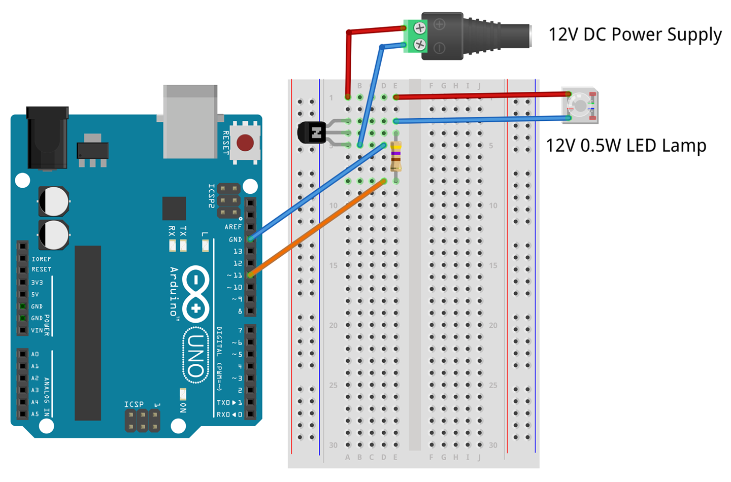
Figure 11-9. Breadboard Layout for Arduino Control Using 2N7000
If you have a higher-power LED lamp, you should use a FQP30N06L as shown in Figure 11-10. Again, you could if you prefer use a TIP120.
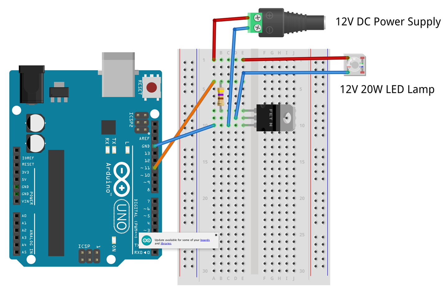
Figure 11-10. Breadboard Layout for Arduino Control Using FQP30N06L
The Arduino test program for this project is listed here and is available in the book downloads (see Recipe 10.2) where the sketch is called ch_11_on_off:
constintoutputPin=11;voidsetup(){pinMode(outputPin,OUTPUT);Serial.begin(9600);Serial.println("Enter 0 for off and 1 for on");}voidloop(){if(Serial.available()){charonOff=Serial.read();if(onOff=='1'){digitalWrite(outputPin,HIGH);Serial.println("Output ON.");}elseif(onOff=='0'){digitalWrite(outputPin,LOW);Serial.println("Output OFF.");}}}
This sketch follows a similar pattern to that of Recipe 10.13. Pin 11 is set to be an output and when a single-command character “1” or “0” is sent from the Serial Monitor (Figure 11-11) digitalWrite is used to turn pin 11 on or off.
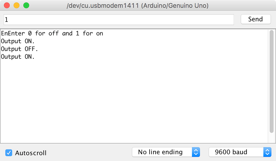
Figure 11-11. Using the Serial Monitor to Turn a Lamp On and Off
You can see the circuit in action in Figure 11-12, where a 12V SLA battery is used to power the lamp.
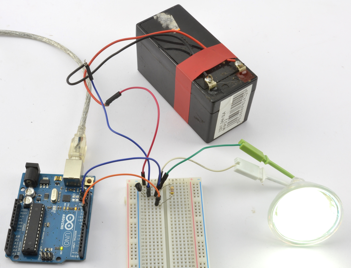
Figure 11-12. Switching a 12V DC Lamp from an Arduino
Although intended as a demonstration circuit, this recipe is actually quite powerful, allowing you to control the lamp from your computer.
See Also
For information on getting started with breadboard, see Recipe 20.1.
For transistor pinouts, see Appendix A.
The basics of an Arduino Uno are described in Recipe 10.1.
To use this same design with Raspberry Pi, see Recipe 11.7.
11.7 Switch with a Raspberry Pi
Solution
The circuits used in Recipe 11.6 will also work just fine if you wire the control connection and GND to a Raspberry Pi rather than an Arduino. Figure 11-13 shows the breadboard layout for using a 2N7000 MOSFET with a Raspberry Pi to switch a 12V LED lamp module.
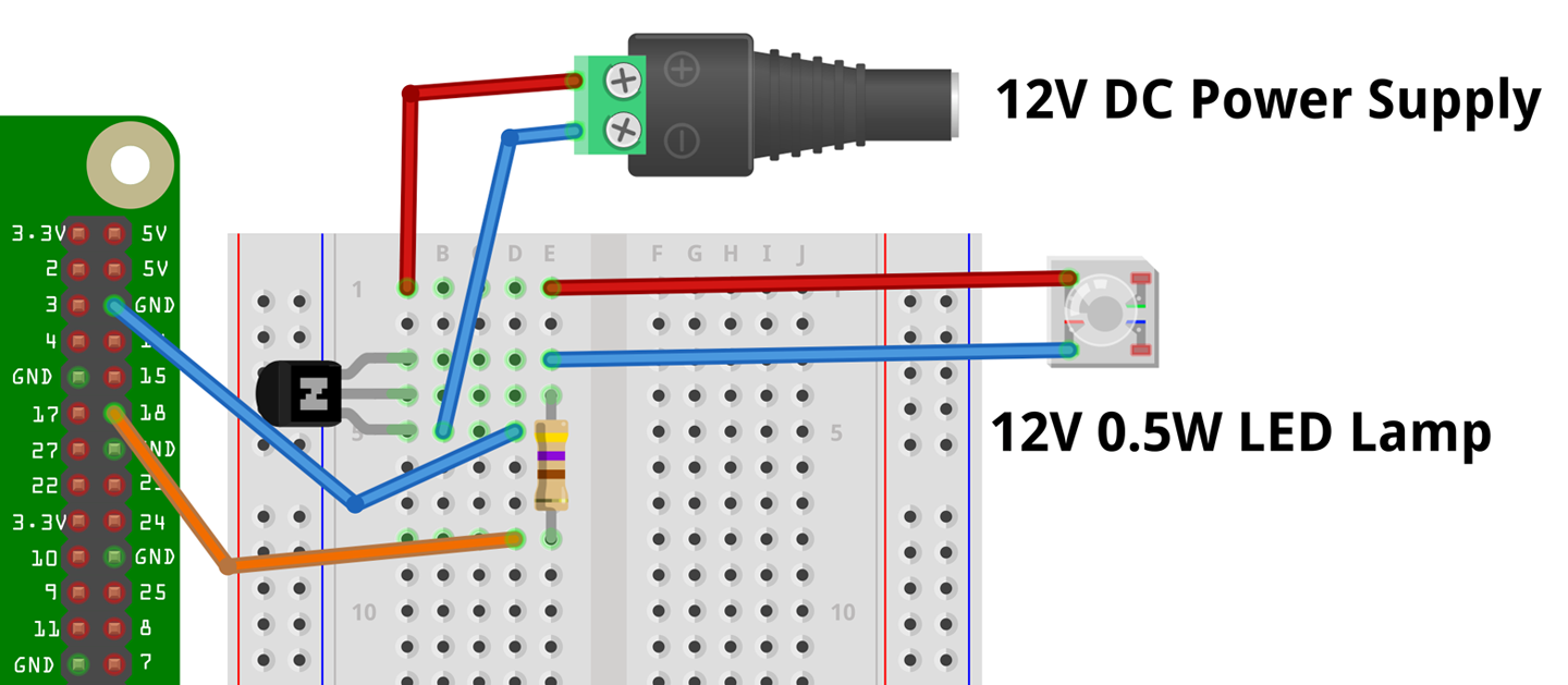
Figure 11-13. Breadboard Layout for Raspberry Pi Control Using 2N7000
To control the lamp, you can use the following program, which is called ch_11_on_off.py and can be found with the downloads for the book (see Recipe 10.4):
importRPi.GPIOasGPIOGPIO.setmode(GPIO.BCM)led_pin=18GPIO.setup(led_pin,GPIO.OUT)try:whileTrue:answer=input("1 for on 0 for off: ")ifanswer==1:GPIO.output(led_pin,True)# LED onelifanswer==0:GPIO.output(led_pin,False)# LED offfinally:("Cleaning up")GPIO.cleanup()
When you run the program you should see this in the terminal session:
$ sudo python ch_11_on_off.py
1 for on 0 for off: 1
1 for on 0 for off: 0
When you enter 1, the lamp should light (pressing 0 will turn it off again).
Discussion
As with Recipe 11.6 you can also use other transistors than the 2N7000 or FQP20N06L MOSFETs.
See Also
For information on getting started with breadboards, see Recipe 20.1.
For transistor pinouts, see Appendix A.
The basics of a Raspbery Pi are described in Recipe 10.3.
To use this same design with an Arduino, see Recipe 11.6.
11.8 Reversible Switching
Solution
Use transistors in the half-bridge configuration shown in Figure 11-14.
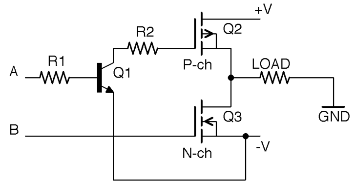
Figure 11-14. A Half-Bridge
This circuit combines elements of Recipe 11.3 and Recipe 11.4 and relies on their being three power lines: +V, –V, and GND in the middle. Thus, the three power lines might be +6V, –6V, and 0V.
The control signals A and B turn on Q2 and Q3, respectively. If A and B are both low with respect to –V no current will flow through the load. If A is high, Q2 will conduct and current will flow through Q2 to the load and then to GND. Conversely, if A is low and B is high, Q3 will conduct and current will flow from GND through the load to –V.
Under no circumstances should A and B both be high, since if both Q2 and Q3 are conducting there will effectively be a short-circuit between +V and –V and a damagingly large current will flow. In fact, if you are connecting A and B to GPIO pins and using software to set them high or low, you should put a small delay in between settings to allow A and B to be high at the same time. For example, to change from A high, B low to A low, B high, you should follow these steps:
- Set A low
- Delay
- Set B high
Discussion
The half-bridge and its relative the full-bridge are often used to control DC motors, where their ability to reverse the direction of the flow of current allows them to reverse the direction in which the motor rotates.
Although it is perfectly possible to build half-bridge circuits from discrete components, it is more common to use an IC. You will meet several of these in Chapter 13.
See Also
For a full-bridge circuit, see Recipe 13.3.
For the FQP27P06 P-Channel MOSFET’s datasheet, see https://www.sparkfun.com/datasheets/Components/General/FQP27P06.pdf.
11.9 Control a Relay from a GPIO Pin
Solution
Use a low-power BJT or MOSFET to switch the power to the relay’s coil as shown in Figure 11-15.
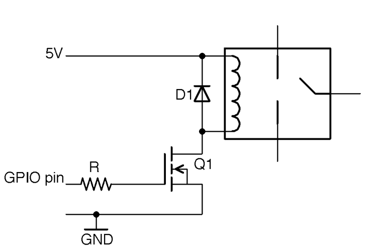
Figure 11-15. Controlling a Relay from a GPIO Pin
A typical relay coil will need about 50mA to activate the relay contacts, which is slightly too much to use an Arduino pin directly and far too much for a Raspberry Pi GPIO pin. A relay with a nominal 5V coil will generally work with a little over 4V if you use a BJT, but supplying the full 5V by way of a MOSFET is generally better. So a good choice for Q1 would be a 2N7000. R is not at all critical, but 1kΩ would be fine.
The diode D1 is called a “freewheeling” or “flyback” diode and provides a discharge path for high voltages generated as the relay coil is switched off, which protects Q1.
Discussion
Building a design like this on a breadboard can be a little tricky, as most common relay packages don’t have pins that will fit into the breadboard, so you may have to solder short extension wires to the relay coil or use a prototyping setup like the MonkMakes Protoboard that has a place to solder a relay. Figure 11-16 shows the breadboard layout for using a relay with an Arduino and Figure 11-17 for a Raspberry Pi.
To test out the relay on an Arduino and Raspberry Pi, you can use the programs described in Recipe 11.6 and Recipe 11.7, respectively.
Although it can be tempting to try to get away with connecting the relay coil directly to a GPIO pin, this may damage the Arduino or Pi and is most certainly operating outside of the specifications for the Arduino, Raspberry Pi, or relay and cannot be guaranteed to work correctly.
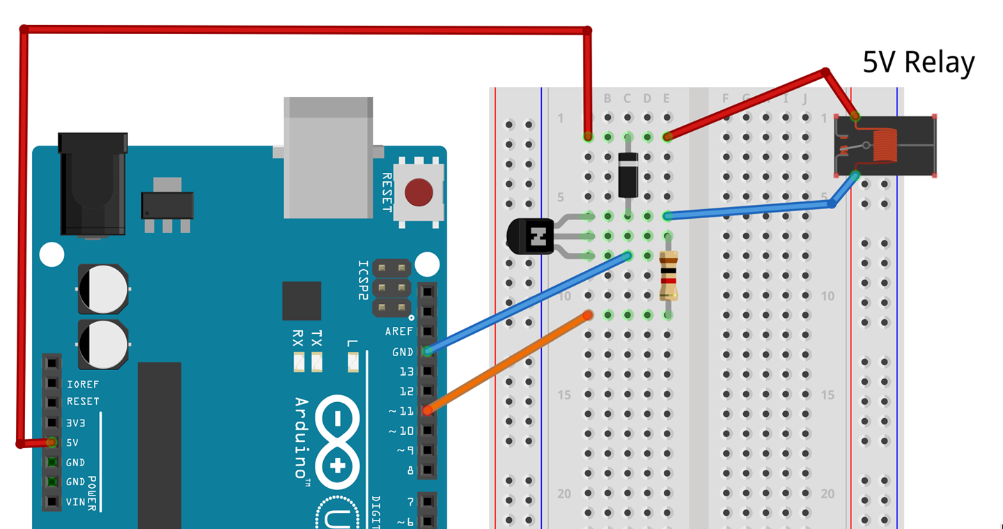
Figure 11-16. Breadboard Layout for Controlling a Relay from an Arduino
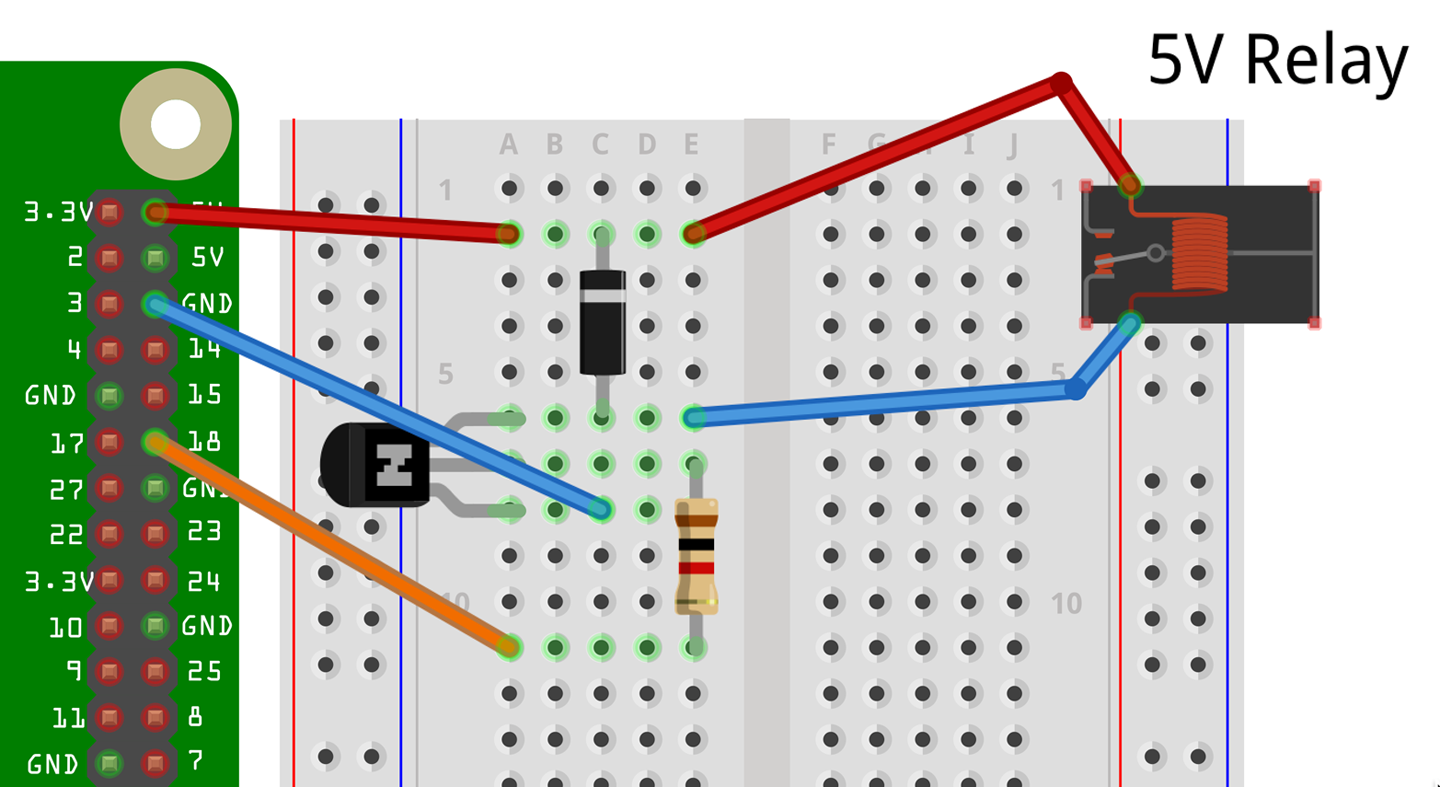
Figure 11-17. Breadboard Layout for Controlling a Relay from a Raspberry Pi
See Also
For information on relays see Recipe 6.4.
11.10 Control a Solid-State Relay from a GPIO Pin
Solution
SSRs are generally opto-isolated, which means that controlling them is as simple as using an LED. In fact, it’s usually easier because in an SSR a series resistor is generally included. Figure 11-18 shows an SSR module connected to a Raspberry Pi. The SSR’s negative input terminal is connected to GND and the positive terminal to a GPIO pin.
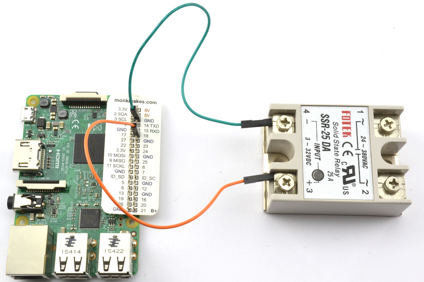
Figure 11-18. Controlling an SSR Using a Raspberry Pi GPIO Pin
Switch AC
Do not use an SSR to control AC unless you are sure you can wire things up safely and you know exactly what you are doing.
Under no circumstances should you work on a live/hot system while you are prototyping, and always use an RCD-protected AC outlet.
See also Recipe 21.12.
Discussion
To test out the relay on an Arduino and Raspberry Pi, you can use the programs described in Recipe 11.6 and Recipe 11.7, respectively.
See Also
A safe and easy way to control AC using an SSR is to use a PowerSwitch Tail.
11.11 Connect to Open-Collector Outputs
Solution
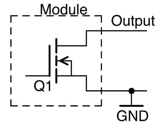
As the name suggests, a circuit that has an open-collector output uses an NPN BJT as an output stage (Figure 11-19) with the implication that the emitter is connected to GND, with no internal connections to the collector except to the output.
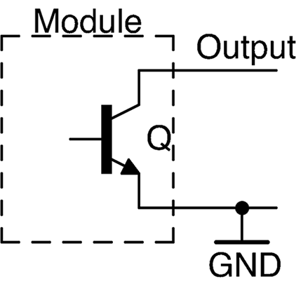
Figure 11-19. A Module with an Open-Collector Output
At first glance this may seem strange, and a common mistake is to treat an open-collector output as a logic output and connect it straight to a GPIO pin. Unless the internal pull-up resistor on the GPIO pin (Recipe 10.7) is enabled, this will not work.
Leaving the collector floating like this has the advantage that by simply using a resistor from the collector to a positive supply, the output voltage of the open collector can be set to match that of the GPIO input you are connecting it to. Figure 11-20 shows how an open-collector output can be used with 3.3V logic (left) and 5V logic (right).
The value of R1 is not critical and needs to lie somewhere in the large range of not exceeding the transistor’s collector current limit and not being succeptable to electrical noise. So, anything between 1kΩ and 1MΩ is fine. Common resistor values for this are 1kΩ and 10kΩ.
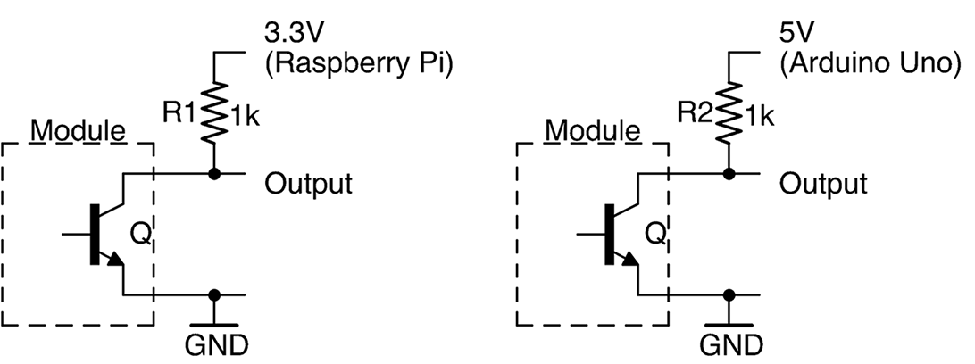
Figure 11-20. Pulling Up an Open-Collector Output
If your GPIO pin has the ability to enable an internal pull-up resistor you can use this instead of an external resistor.
Discussion
If the circuit or module you are using specifies the current rating of the open-collector output, you can use it to directly drive a load (e.g., a relay). The load should be in place of the resistor between the output and a positive voltage supply.
The MOSFET equivalent of an open-collector output is the open-drain output (see Figure 11-21). This can be used in exactly the same way as its BJT equivalent. In fact, it’s not uncommon to find device outputs labeled as open collector that actually use a MOSFET.