Table of Contents for
Electronics Cookbook
 Electronics Cookbook
Published by
O'Reilly Media, Inc., 2017
Electronics Cookbook
Published by
O'Reilly Media, Inc., 2017
- Cover
- nav
- Electronics Cookbook
- Electronics Cookbook
- Preface
- Theory
- Resistors
- Capacitors and Inductors
- Diodes
- Transistors and Integrated Circuits
- Switches and Relays
- Power Supplies
- Batteries
- Solar Power
- Arduino and Raspberry Pi
- Switching
- Sensors
- Motors
- LEDs and Displays
- Digital ICs
- Analog
- Operational Amplifiers
- Audio
- Radio Frequency
- Construction
- Tools
- Parts and Suppliers
- Arduino Pinouts
- Raspberry Pi Pinouts
- Units and Prefixes
- Index
- About the Author
- Colophon
Chapter 15. Digital ICs
15.0 Introduction
In many projects the only digital IC you will need is a microcontroller. With sufficient GPIO pins you can do most digital tasks. In this chapter, you will find recipes for digital ICs that still manage to find a role in modern electronics design.
Sometimes, a single digital logic IC is all you need. A single digital logic IC is often cheaper and removes the need for programming that would otherwise arise if you used a microcontroller.
15.1 Protecting ICs from Electrical Noise
Solution
Use a 100nF capacitor as close as possible to the power pins of the digital IC. The shorter the leads to the capacitor the better.
This process of connecting a capacitor with short circuit board tracks to the power pins of an IC is called “decoupling” because each IC has its own little reservoir of charge and will therefore not be “coupled” to a neighboring capacitor by affecting its power supply. Capacitors used in this way are also called “bypass” capacitors.
Figure 15-1 shows a circuit board containing a digital IC with a 100nF multilayer ceramic (MLC) capacitor for both a through-hole and SMD.
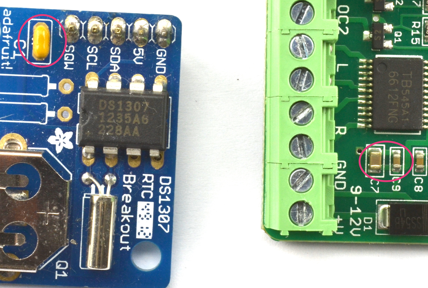
Figure 15-1. Decoupling Capacitors
The circuit board on the right of Figure 15-1 actually has two capacitors in parallel as the decoupling capacitor. The smaller one is 100nF and the larger one 10µF. You may think that the effect of the 100nF would be lost, but its lower ESR (see Recipe 3.2) allows it to respond faster to pulses of power consumption from the chip. So, the 10µF capacitor is in turn providing a larger local energy store for the smaller capacitor and IC to draw on, but one that has a higher ESR and therefore cannot respond as quickly. Such an arrangement of ever-decreasing capacitor values as you approach the power rails of the IC is particularly common where larger currents are being switched such as in motor controllers and audio power amplifiers.
Discussion
Digital ICs contain lots of transistors that switch very quickly. The decoupling capacitor provides a little reservoir of charge so that this switching does not result in excessive electrical noise on the power lines that could go on to affect other parts of the circuit.
It is considered to be good practice to include a decoupling capacitor next to every digital IC. In fact, this is also true of analog ICs.
See Also
For more information on capacitors, see Chapter 3.
15.2 Know Your Logic Families
Discussion
Logic-gate ICs, like the mafia, are arranged into families. TTL (transistor transistor logic) used to be a popular choice, but is now totally obsolete unless you are repairing an equally obsolete computer from the last century. TTL chips starting with the number 74 (e.g., 7400) used to compete with CMOS chips with names that started with 40 (e.g., 4011). Each had their own overlapping ranges of logic gates, flip-flops, shift registers, and counters.
TTL was faster than CMOS, but CMOS used less current and was far less fussy about its supply-voltage range. Now these two families have merged into a single “best-of-both-worlds” family called high-speed CMOS. If you started playing with electronics in the 1970s, you can still find your favorite logic ICs from both families but under one name starting with 74HC. For instance, the 7400 of old is now the 74HC00 and the 4011 of old is now called the 74HC4001.
A high-speed CMOS chip has a supply-voltage range of 2V to 6V and only consumes about 1µA until it starts switching. Their outputs can also generally source or sink 4mA at their outputs (per gate).
The original 40xx CMOS is still available and can be useful where you need a greater power-supply range than high-speed CMOS can provide.
See Also
For the datasheet of a typical high-speed CMOS device, see http://www.ti.com/lit/ds/symlink/sn74hc00.pdf.
15.3 Control More Outputs Than You Have GPIO Pins
Solution
Use a serial-to-parallel shift register such as the 74HC4094 and write some code to load its registers with data using a serial interface that only requires three pins. LEDs can then be attached to the outputs. Figure 15-2 shows a schematic for this.
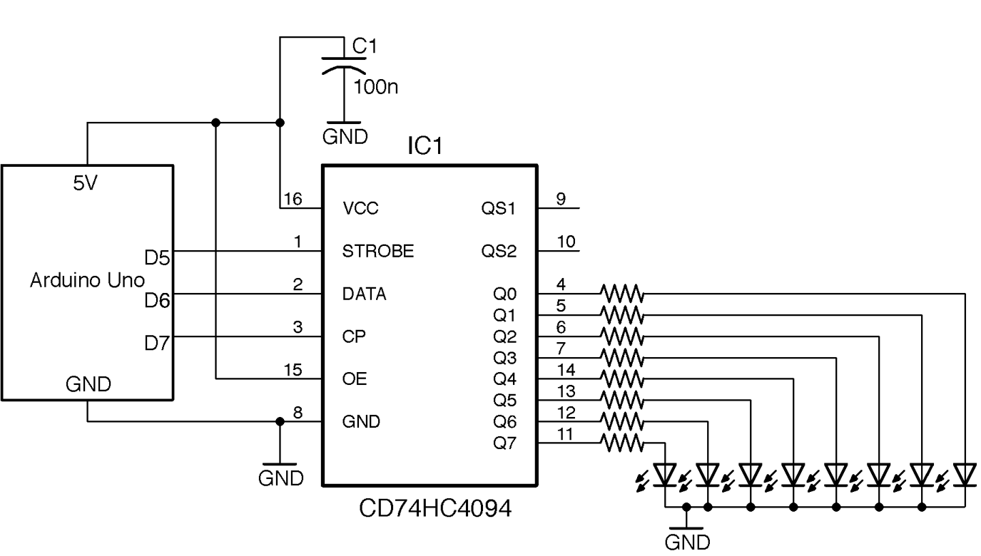
Figure 15-2. Connecting an 74HC4094 to an Arduino Uno
The total current allowed by the 74HC4094 is 50mA so assuming 6mA per LED, a suitable series resistor would be 680Ω if all the LEDs are lit at the same time, to allow 8 x 6mA = 48mA.
Arduino software
You can find the Arduino code to send data to the shift register with the downloads for the book (Recipe 10.2) in the sketch ch_15_sift_reg:
constintstrobePin=5;constintdataPin=6;constintclockPin=7;voidsetup(){pinMode(strobePin,OUTPUT);pinMode(dataPin,OUTPUT);pinMode(clockPin,OUTPUT);Serial.begin(9600);Serial.println("Enter Byte");}voidloop(){if(Serial.available()){charbits=Serial.parseInt();shiftOut(dataPin,clockPin,MSBFIRST,bits);digitalWrite(strobePin,HIGH);delayMicroseconds(10);digitalWrite(strobePin,LOW);Serial.println(bits,2);}}
This sketch uses the Arduino shiftOut function to send the serial data and uses these parameters: the pin to send the data on, the clock pin, a flag to determine the order the data is sent (in this case, most significant bit [MSB] first), and the actual data to send.
If you open the Arduino Serial Monitor, you will be prompted for a value to load into the shift register. This value will be shifted in and then a confirmation of the data in binary will be displayed as shown in Figure 15-3. The value entered should be a decimal value between 0 and 255. This value will be echoed in binary in the Serial Monitor for confirmation.
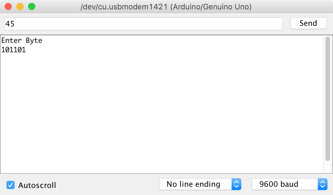
Figure 15-3. Sending Data to the Shift Register
Raspberry Pi software
The following test program assumes you have connected the STROBE pin of the 74HC4094 to GPIO18, the DATA pin to GPIO23, and the CLOCK pin to GPIO24.
The Python code (ch_15_shift_reg.py) follows a similar pattern as that of the Arduino, but in this case we have to implement the shift_out function. This sets the data_pin to the eighth bit of the data, and then pulses the clock_pin before shifting the data left by one bit position, and so on for all eight bits in MSB first order:
importRPi.GPIOasGPIOimporttimeGPIO.setmode(GPIO.BCM)strobe_pin=18data_pin=23clock_pin=24GPIO.setup(strobe_pin,GPIO.OUT)GPIO.setup(data_pin,GPIO.OUT)GPIO.setup(clock_pin,GPIO.OUT)defshift_out(bits):# MSB first. 8 bitsforiinrange(0,8):b=bits&0b10000000bits=bits<<1GPIO.output(data_pin,(b==0b10000000))time.sleep(0.000001)GPIO.output(clock_pin,True)time.sleep(0.000001)GPIO.output(clock_pin,False)time.sleep(0.000001)try:whileTrue:bits=input("Enter Byte ")(bin(bits))shift_out(bits)GPIO.output(strobe_pin,True)time.sleep(0.000001)GPIO.output(strobe_pin,False)finally:("Cleaning up")GPIO.cleanup()
Discussion
Figure 15-4 shows the logical diagram for the 74HC4094.
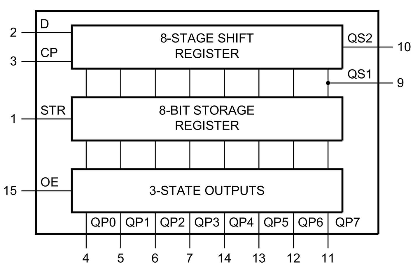
Figure 15-4. The 74HC4094
The 74HC4094 is a serial-to-parallel shift register. The 8-stage shift register’s data is set a bit at a time by setting the data (D) pin either HIGH or LOW and then pulsing the clock (CP) pin to transfer that bit. The data pin is then set to the next value and the clock pulsed again to shift the bit already in the shift register along one position and then add the new bit at the beginning. This process continues until all eight bits are loaded into the shift register.
The contents of the shift register are not actually transferred to the 74HC4094’s outputs until the strobe pin (STR) is pulsed.
The 74HC4094 also has an output enable (OE) pin that switches all eight outputs either to a high impedance state or to the bit pattern of HIGHs and LOWS in the 3-state-outputs register. If you connect this OE pin to a PWM output you can use it to control the brightness of all the LEDs at the same time.
You can cascade a number of shift registers together by tying their clocks together and attaching the QS2 data output from one shift register to the data input of the next.
See Also
Another way of controlling lots of LEDs from a small number of GPIO pins is to use Charlieplexing (Recipe 14.6).
You can find the datasheet for the 74HC4094 here: http://bit.ly/2mqB0ET.
For more information on the Arduino shiftOut function, see http://bit.ly/2msRHAg.
15.4 Build a Digital Toggle Switch
Solution
Use an 74HC00 IC to make a reset-set flip-flop as shown in Figure 15-5.
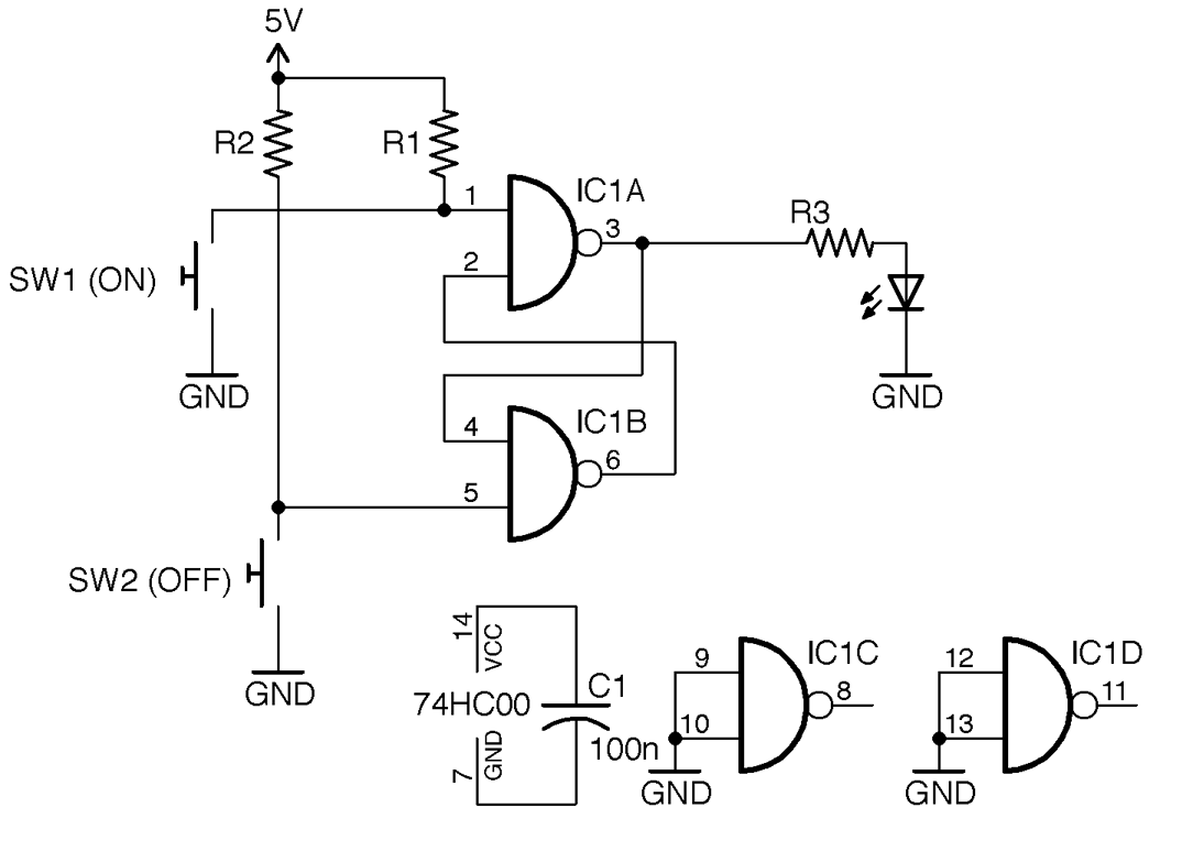
Figure 15-5. Using Flip-Flop and Push Buttons to Switch an LED On and Off
When SW1 is pressed the LED will light and stay lit until SW2 is pressed.
Discussion
R1 and R2 are pull-up resistors that keep the inputs to flip-flop high until the buttons are pressed. One advantage of this way of switching is that if the switches bounce (Recipe 12.1) it will have no effect on the operation of the circuit.
Note that in Figure 15-5 the inputs of the two unused gates in the 74HC00 are tied to ground. This is considered good practice as it prevents the otherwise floating inputs from causing the gates to oscillate in time with electrical noise.
In addition to switching an LED on or off, you could adapt this circuit to switch large loads with a transistor by combining it with Recipe 11.1 or Recipe 11.3.
See Also
You can find the datasheet for the 74HC00 here: http://bit.ly/2lLK0R5.
15.5 Reduce a Signal’s Frequency
Solution
Use a frequency-divider IC such as the 8-stage 74HC590 in the arrangement shown in Figure 15-6.
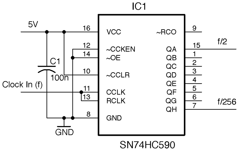
Figure 15-6. A Frequency Divider Using the 74HC590
The output at QA will be half the input frequency f, QB a quarter, and so on until QH has an output frequency of 1/256 of the input frequency.
Discussion
For most designs it is preferable to use a microcontroller when it comes to things like counting. However, counting clock cycles with a microcontroller is significantly slower than the clock frequency of the microcontroller itself. So, a maximum frequency might be a few hundred kHz. To count higher frequencies, QH or one of the other outputs of the 74HC590 could be connected to a digital input on a microcontroller to allow frequencies up to the 24MHz maximum the 74HC590 allows.
See Also
You can find the datasheet for the 74HC590 here: http://www.nxp.com/documents/data_sheet/74HC590.pdf.
15.6 Connect to Decimal Counters
Solution
Connect the clock and reset the pins of a 74HC4017 decimal counter IC to an Arduino or Raspberry Pi and attach LEDs to the outputs of the 74HC4017 with suitable current-limiting resistors as shown in Figure 15-7.
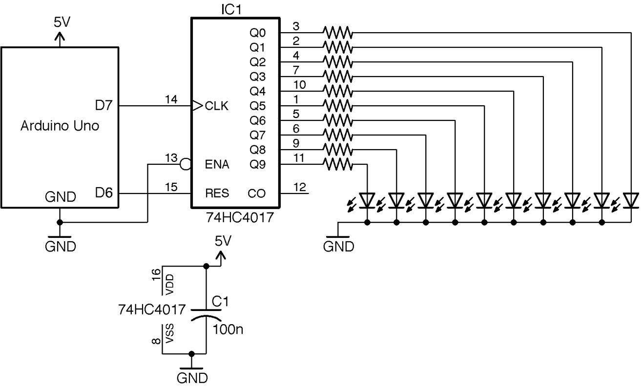
Figure 15-7. Using a 74HC4017 Decimal Counter with an Arduino
The 74HC4017 is a decade counter with decoded outputs. That is, each time it receives a pulse on its clock (CLK) pin it advances to the next output. So, first Q0 is high, then Q1, and so on. The reset pin (RES) sets the counter back to the first output Q0.
Since only one of the LEDs is ever on at a time, the full 20mA output of the 74HC4017 can be used to drive the LEDs.
Arduino software
The Arduino sketch ch_15_decade_counter is given here. You can find it with the downloads for the book (Recipe 10.2):
constintresetPin=6;constintclockPin=7;voidsetup(){pinMode(resetPin,OUTPUT);pinMode(clockPin,OUTPUT);Serial.begin(9600);Serial.println("Enter digit 0..9");}voidloop(){if(Serial.available()){intdigit=Serial.parseInt();setDigit(digit);}}voidsetDigit(intdigit){digitalWrite(resetPin,HIGH);delayMicroseconds(1);digitalWrite(resetPin,LOW);for(inti=0;i<digit;i++){digitalWrite(clockPin,HIGH);delayMicroseconds(1);digitalWrite(clockPin,LOW);delayMicroseconds(1);}}
The code starts by pulsing the reset pin so that the output Q0 will be high. It then issues the number of pulses to the clock pin requested by the number sent from the Serial Monitor.
The reason the LEDs don’t flicker and you don’t see the LEDs before the selected LED flash is that this pulsing happens very quickly (in fact, in a few millionths of a second).
Raspberry Pi software
The equivalent Python sketch for the Raspberry Pi assumes you have GPIO18 connected to the reset pin of the 74HC4017 and GPIO23 connected to the clock pin.
The program is called ch_15_decade_counter.py. See Recipe 10.4 for information on installing the example programs:
importRPi.GPIOasGPIOimporttimeGPIO.setmode(GPIO.BCM)reset_pin=18clock_pin=23GPIO.setup(reset_pin,GPIO.OUT)GPIO.setup(clock_pin,GPIO.OUT)defset_digit(digit):GPIO.output(reset_pin,True)time.sleep(0.000001)GPIO.output(reset_pin,False)time.sleep(0.000001)foriinrange(0,digit):GPIO.output(clock_pin,True)time.sleep(0.000001)GPIO.output(clock_pin,False)time.sleep(0.000001)try:whileTrue:digit=input("Enter digit 0..9 ")set_digit(digit)finally:("Cleaning up")GPIO.cleanup()
The program works in just the same way as its Arduino counterpart.
Discussion
Using a counter like the 74HC4017 can be useful when multiplexing an LED display (Recipe 14.5), as you can use it to select each digit of a 7-segment display or column of an LED matrix, without tying up too many GPIOs.
See Also
You can find the datasheet for the 74HC4017 here: http://www.nxp.com/documents/data_sheet/74HC_HCT4017.pdf.