Table of Contents for
Electronics Cookbook
 Electronics Cookbook
Published by
O'Reilly Media, Inc., 2017
Electronics Cookbook
Published by
O'Reilly Media, Inc., 2017
- Cover
- nav
- Electronics Cookbook
- Electronics Cookbook
- Preface
- Theory
- Resistors
- Capacitors and Inductors
- Diodes
- Transistors and Integrated Circuits
- Switches and Relays
- Power Supplies
- Batteries
- Solar Power
- Arduino and Raspberry Pi
- Switching
- Sensors
- Motors
- LEDs and Displays
- Digital ICs
- Analog
- Operational Amplifiers
- Audio
- Radio Frequency
- Construction
- Tools
- Parts and Suppliers
- Arduino Pinouts
- Raspberry Pi Pinouts
- Units and Prefixes
- Index
- About the Author
- Colophon
Chapter 18. Audio
18.0 Introduction
Audio electronics is all about generating signals and amplifying them enough to power a loudspeaker so that you can hear them.
This chapter contains a number of amplification and signal-generation recipes. Any resource that deals with audio-power amplifier design will explain the different classes of amplifiers, which are designated by A, B, AB, and D, and some other more exotic designs. For the most part, these letters designate how the amplifier is constructed from bipolar junction transistors and how they are biased. Since these days there is no real cost or even quality advantage (apart from the most demanding audiophile) to building an amplifier from separate transistors rather than just using an IC, I feel it is only necessary here to highlight the most common designs along with their main characteristics:
- Class A
- Low distortion but very inefficient, produces a lot of heat.
- Class B and AB
- A push-pull design. More distortion than A but much more efficient. AB is the same as B but with compensation to reduce the distortion when the amplifier switches over from pushing the loudspeaker to pulling it (see Recipe 18.4)
- Class D
- Digital amplifier. Higher distortion than A or B but very energy efficient (see Recipe 18.5)
Before launching into the construction of your own amplifier designs, think about whether you need to build the amplifier from scratch. For most one-off projects, it is easier and cheaper to use ready-made modules or even USB-powered amplified speakers.
When it comes to generating sound waves from an Arduino, you can easily generate tones. The Raspberry Pi with its large amount of memory and sophisticated hardware allows MP3 and other sounds files to be played through its audio jack, which can then be connected to an external amplifier.
18.1 Play Sounds on an Arduino
Solution
You can experiment with generating tones and driving a speaker from an Arduino if you connect a speaker to an Arduino as shown in Figure 18-1.
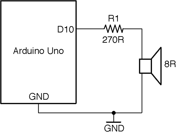
Figure 18-1. Generating Sound with an Arduino
The sketch ch_18_speaker can be found with the downloads for the book (see Recipe 10.2):
constintoutputPin=10;voidsetup(){pinMode(outputPin,OUTPUT);Serial.begin(9600);Serial.println("Enter frequency 100-8000 Hz (0 off)");}voidloop(){if(Serial.available()){intf=Serial.parseInt();if(f==0){noTone(outputPin);}else{tone(outputPin,f);}}}
The Arduino tone function takes two parameters, the pin to generate a tone on and the frequency of the tone to generate as a long integer value. The tone function can generate frequencies from 31Hz to 65,535Hz.
To use it, open the Arduino Serial Monitor and make sure you have the Line Ending drop-down list set to “No line ending” then type in a frequency in Hz and click Send.
The 5V signal generated by the tone command is a little too high a voltage to feed directly into an amplifier. It should be reduced to below 2V or so using a pair of resistors as a voltage divider. 1kΩ and 270Ω resistors with the 270Ω resistor to GND will reduce the output by a factor of about 5.
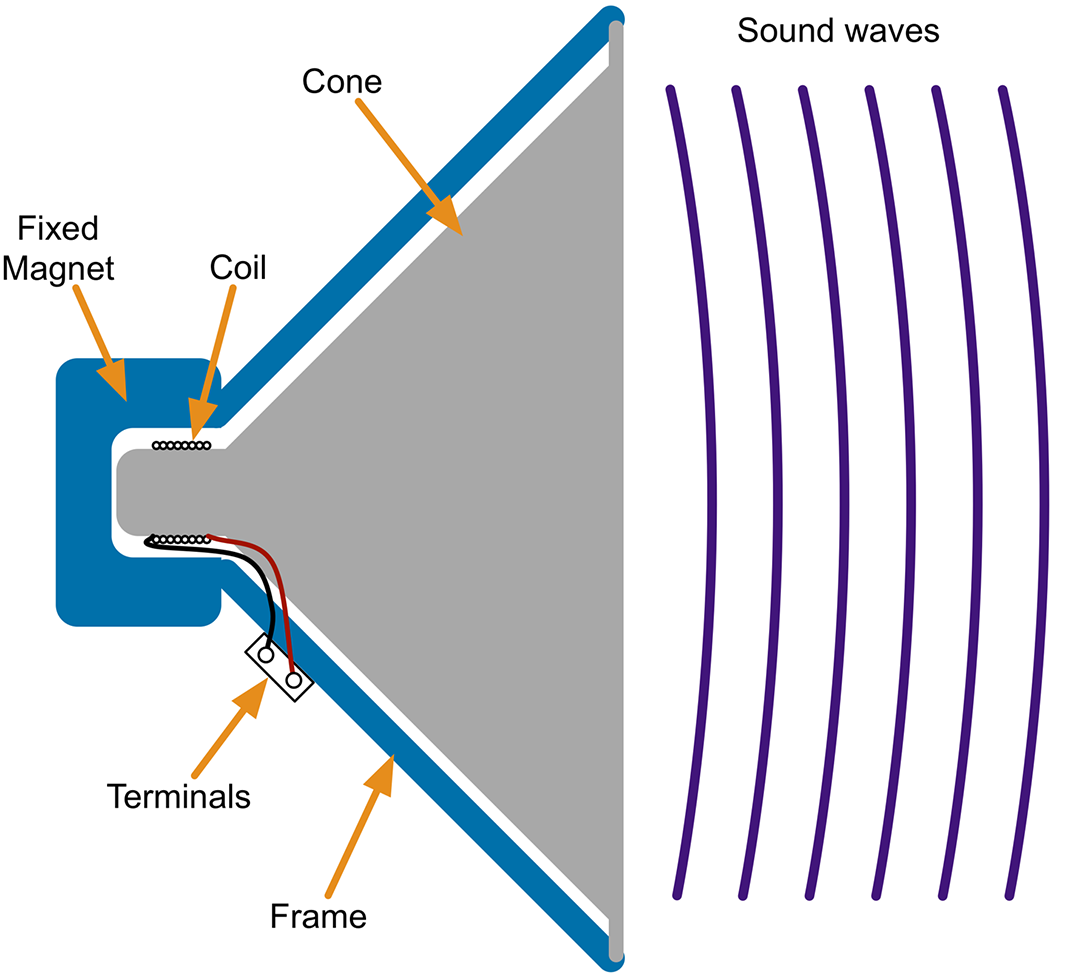
Figure 18-2. The Structure of a Loudspeaker
Discussion
A loudspeaker is an inductive load, so, like the coil of a relay, there is a risk of voltage spikes arising that could damage the GPIO pin driving the speaker. In reality, when using a small speaker driven through a resistor, these spikes will be sufficiently low in energy for the antistatic protection of the GPIO pin to take care of them.
Making crude square-wave buzzing has its place, but the Arduino is actually capable of more sophisticated sound generation using the Mozzi library, which uses a high-frequency PWM signal at 32.7kHz to generate the sound file using PWM.
To try out Mozzi and hear the difference between the square and sinewaves, install the Mozzi library and then run the example program included with the Mozzi library 01. Basics→Sinewave.
You will need to change the connection to R1 from Arduino pin 10 to pin 9 that is used by Mozzi.
If you want to know how Mozzi sounds are generated skip ahead to Recipe 18.1.
See Also
For using a voltage divider, see Recipe 2.6.
For oscillator recipes that do not require an Arduino, see Recipe 16.2, Recipe 16.5, and Recipe 16.6.
To generate better-sounding audio from an Arduino, take a look at the Arduino Mozzi library.
18.2 Play Sound with a Raspberry Pi
Solution
When it comes to hardware, most models of Raspberry Pi have a 3.5mm headphone-style jack socket that can be attached to a stereo amplifier and speakers.
In recent versions of Raspbian, you will find the OMXPlayer preinstalled. To play a sound file, you just need to name the sound file you want to play OMXPlayer. For example:
$ omxplayer file.mp3
If you need to play the sound file from within a Python program you can use the os.system command to run OMXPlayer, as follows:
importosos.system('omxplayer file.mp3')
Discussion
In addition to the headphone jack, sound can also be played through the HDMI connector. The OMXPlayer software should automatically play through HDMI unless the audio jack has something plugged into it.
You can choose the channel the sound should be played through by using the -o option, which can have a value of either local (audio socket) or hdmi. For example:
$ omxplayer -o hdmi file.mp3
See Also
You can find out more about the OMXPlayer here: http://elinux.org/Omxplayer. In addition to sound files in most formats, the player can also play video files.
For an alternative method of playing sound files using the Pygame library, see http://bit.ly/2mt4eDM.
The Raspberry Pi Zero does not have an audio jack, but you can still use it to play audio; see http://bit.ly/2mIjZH9 for details.
18.3 Incorporate an Electret Microphone Into a Project
Solution
Use a single-supply rail-to-rail op-amp like the OPA365 and amplify the signal by a factor of between 30 and 100. A gain of 30 is about right if you will be speaking directly into the microphone and 100 if you want the microphone to be useful in picking up ambient sounds.
Figure 18-3 shows the schematic for the microphone preamp with a gain of 101. For a discussion of how to set the gain, see Recipe 17.5.
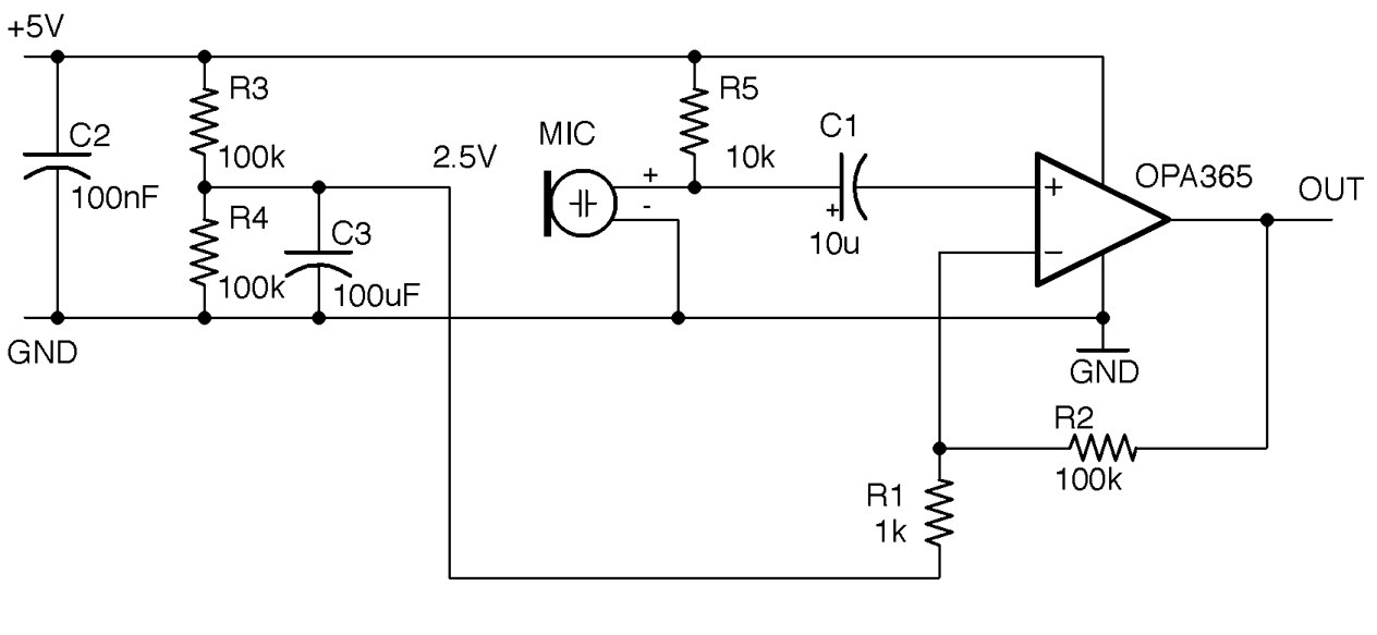
Figure 18-3. An Electret Microphone Preamplifier
C1 is used to “AC couple” the weak output from the microphone to the noninverting input of the op-amp. It allows only the AC part of the signal from the mic, rejecting the DC bias that would otherwise be present.
Discussion
Electret microphones operate like capacitors. Sound waves effectively move one plate of the capacitor closer or further away. The plates of the electret are charged during manufacture and retain that charge for the life of the microphone. These changes in capacitance are converted into a small voltage using an FET transistor built into the microphone. The microphone module is polarized and must be connected the right way around. You also need to supply a drain resistor for the FET (R5 in Figure 18-3).
The circuit of Figure 18-3 will produce an output centered around 2.5V that can be connected directly to an Arduino’s analog input and allow you to do things like measure the maximum sound level.
Figure 18-4 shows the circuit used with an Arduino Uno.
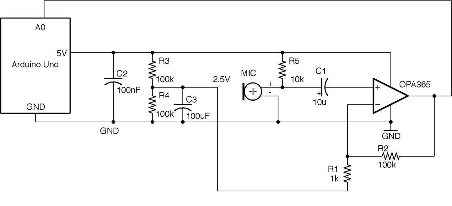
Figure 18-4. An Arduino Sound-Level Meter
This circuit can be built on a breadboard, but the OPA365 is only available as an SMD, so you will need to use a SOT-23 or SOIC breakout board such as the one from Schmartboard.com, as shown in Figure 18-5.
The Arduino sketch ch_18_sound_meter (see Recipe 10.2) samples the analog input A0 for 100ms and then reports on the maximum amplitude it sampled (Figure 18-6). You could modify this sketch to trigger some action if the sound level rises above a certain level.
Note that the maximum possible reading will be 512 (half the full analog value reading):
constintsoundPin=A0;constlongsamplePeriod=100;// mslonglastSampleTime=0;intmaxAmplitude=0;intn=0;voidsetup(){Serial.begin(9600);}voidloop(){longnow=millis();if(now>lastSampleTime+samplePeriod){processSoundLevel();n=0;maxAmplitude=0;lastSampleTime=now;}else{intamplitude=analogRead(soundPin)-512;if(amplitude>maxAmplitude){maxAmplitude=amplitude;}n++;}}voidprocessSoundLevel(){// replace or add your own code to use maxAmplitudeSerial.("Of ");Serial.(n);Serial.(" samples, the maximum was ");Serial.println(maxAmplitude);}
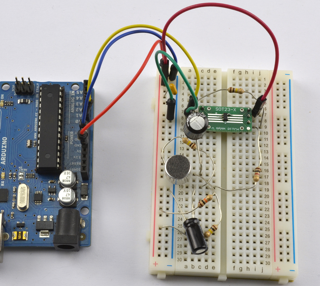
Figure 18-5. Using an SMT OPA365 on a Breadboard
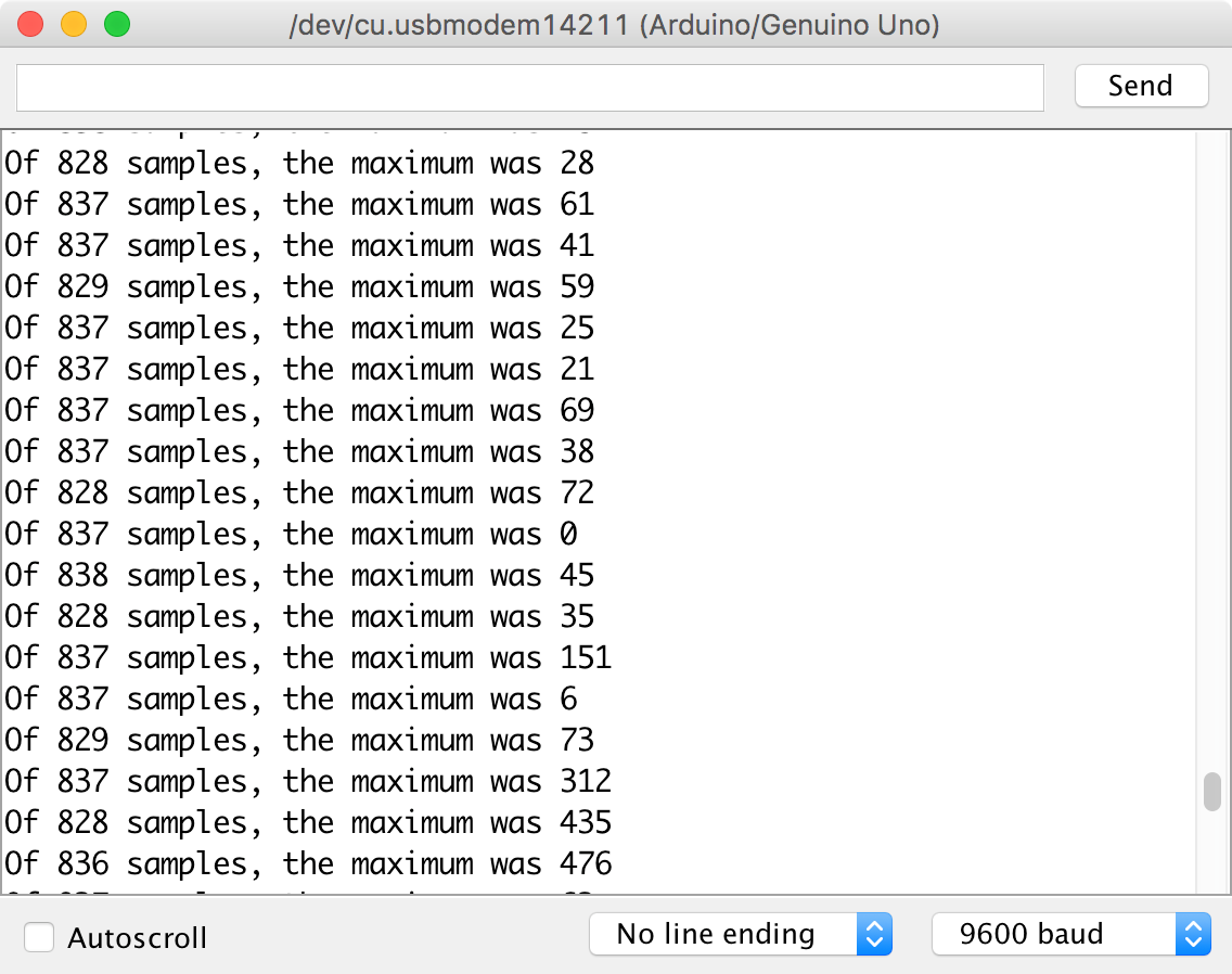
Figure 18-6. Serial Monitor Reporting Sound Level
See Also
Ready-made microphone preamplifier modules are available that use electret microphones, for example: https://www.sparkfun.com/products/12758.
Alternatively, you can use the type of microphone found in cellphones called MEMS (microelectromechanical systems). These are essentially microphones on a chip. SparkFun and others sell breakout boards for these extremely tiny microphones, such as this one: https://www.sparkfun.com/products/9868.
For information on using analog inputs with an Arduino, see Recipe 10.12.
18.4 Make a 1W Power Amplifier
Problem
You need a low-cost power amplifier to power a small speaker at low volumes, say to accompany an FM radio receiver as in Recipe 19.3.
Solution
Use a power-amp IC like the TDA7052, which will work with any power supply from 3V to 15V and can supply 1W of power into an 8Ω speaker. The schematic for a simple amplifier using this device is shown in Figure 18-7.
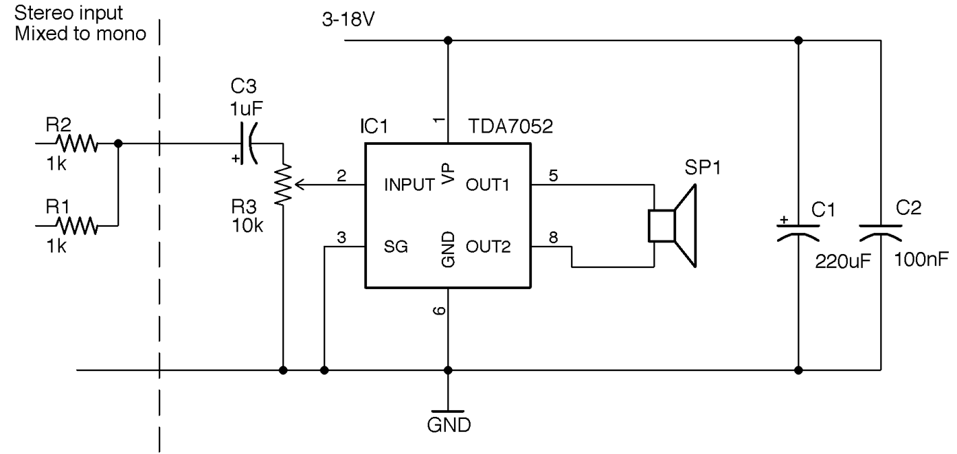
Figure 18-7. Using the TDA7052 1W Linear Power Amplifier
R1 and R2 are only provided to show how to mix the left and right signals of a stereo audio source to mono. If you have a mono source, just connect it directly to C3.
R3 acts as a volume control, and if the sound source has a volume control, you can replace this with two fixed resistors acting as a voltage divider.
C1 and C2 provide energy stores for the rapidly changing load of the IC as it drives the speaker. C1 should be placed as close to IC1 as possible.
Discussion
Figure 18-8 shows how you can build an amplifier like this on a solderless breadboard. In this case, the breadboard is stuck to a Monk Makes Protoboard for the convenience of being able to attach the speaker to screw terminals and use the audio jack and power jack.
What Counts as a “Power” Amplifier?
1W is not very powerful compared with the 20W or more you will generally find in a home stereo system. An amplifier is generally considered a “power” amp if it has enough current amplification to drive a low impedance load (i.e., 4 or 8Ω loudspeakers).
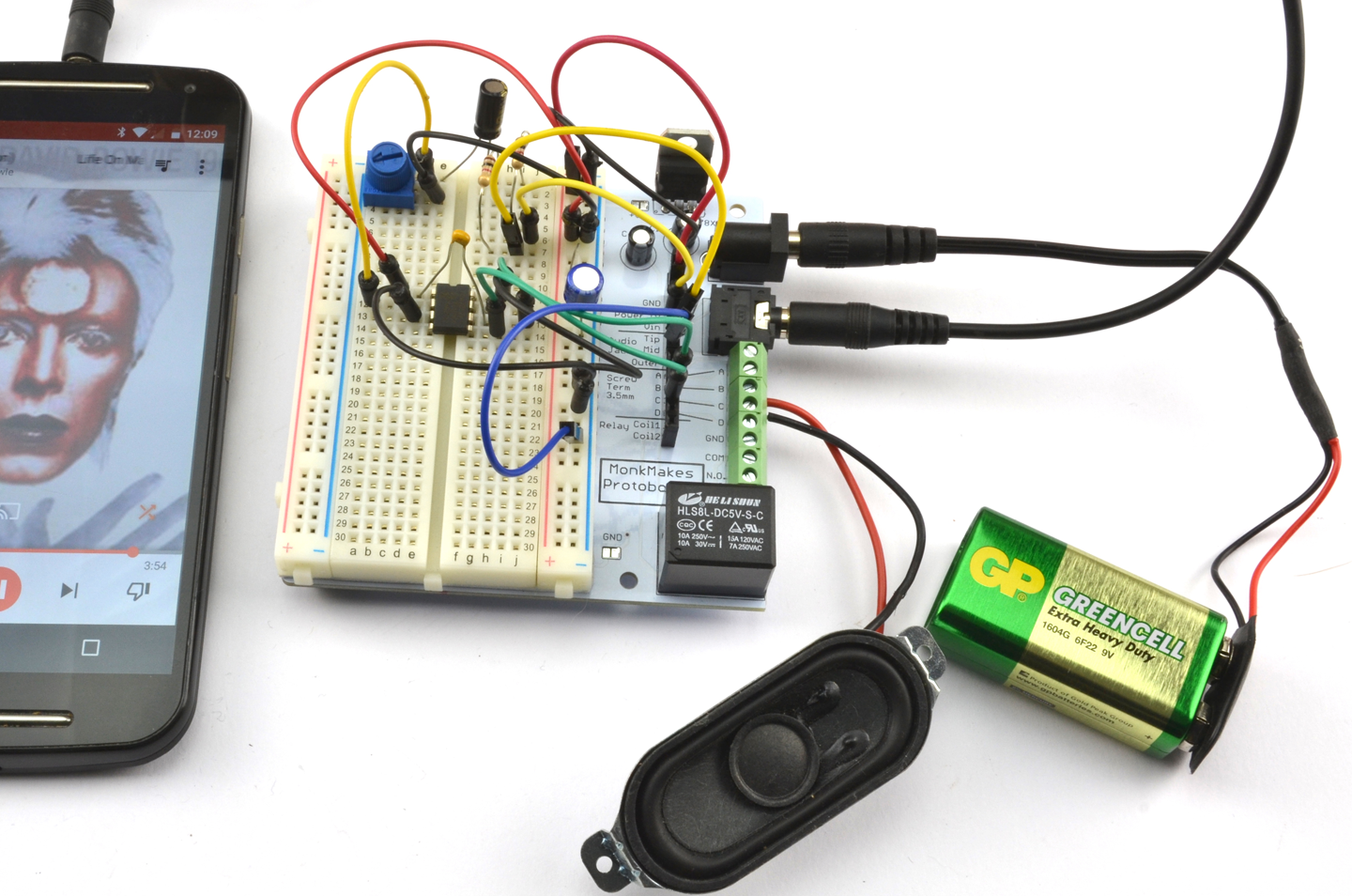
Figure 18-8. A 1W Power Amplifier Built on a Breadboard
See Also
The TDA7052 datasheet can be found here: http://bit.ly/2nA0GgB.
For high-power class-D design, see Recipe 18.5.
18.5 Make a 10W Power Amplifier
Solution
Use a class-D digital amplifier IC such as the TPA3122D2. The schematic for this is shown in Figure 18-9.
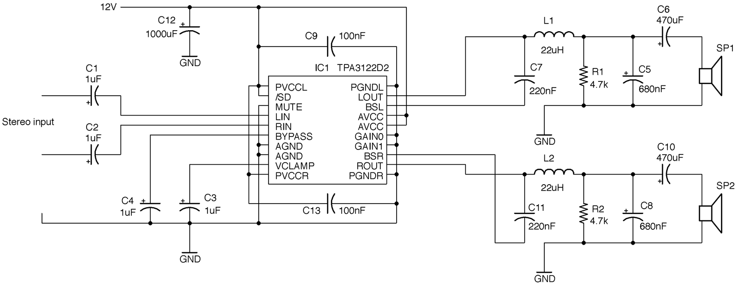
Figure 18-9. A Class-D Power Amplifier Using a TPA3122D2
This design is a modified version of the one found on page 14 of this chip’s datasheet. It will operate on a supply voltage of 10 to 30V, but at a convenient 12V will supply about 7.5W per channel into 4Ω speakers. For more power you need to increase the supply voltage.
The TPA3122D2 is a 20-pin DIL (dual in-line) IC that makes the design very suitable for prototyping on a breadboard (Figure 18-10).
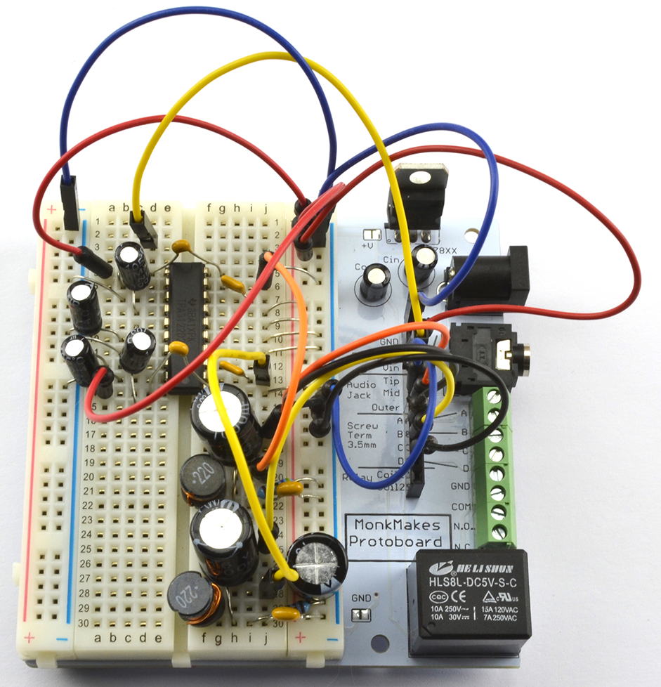
Figure 18-10. A Class-D Power Amplifier Using a TPA3122D2 on a Breadboard
One interesting feature of the TPA3122D2 is that the gain is set by two digital inputs that set the gain to one of four values. Table 18-1 shows how these pins are used. In the schematic of Figure 18-9 the lowest gain of 20dB is selected.
| GAIN1 | GAIN0 | Amplifier gain (dB) |
|---|---|---|
| LOW | LOW | 20 |
| LOW | HIGH | 26 |
| HIGH | LOW | 32 |
| HIGH | HIGH | 36 |
Discussion
Unlike traditional amplifier designs like that of Recipe 18.4 class-D amplifiers are extremely efficient, transferring sometimes over 90% of the power supplied to them to the output load (loudspeaker).
Figure 18-11 shows how a class-D amplifier works.
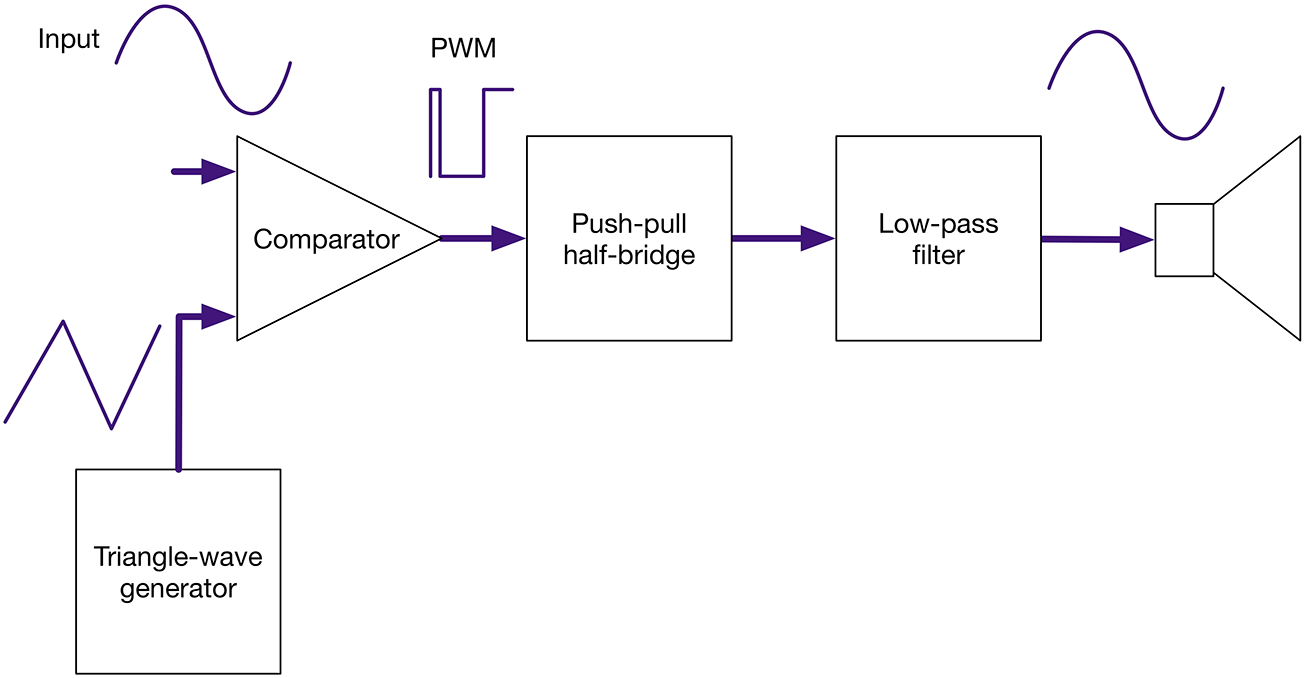
Figure 18-11. Block Diagram of a Class-D Amplifier
The input signal is converted into high-frequency PWM (250kHz in the case of the TPA3122D2) by a combination of a triangle-wave generator and comparator. This is actually the way Recipe 16.9 works. The length of the pulse will be determined by the time it takes for the triangular signal to exceed the value of the analog input. Since the analog input is a much lower frequency than the triangle wave, it can be considered as having a constant instantaneous value, while the triangle wave is “sampling” it. It’s a bit like driving fast past someone who is walking—the pedestrian is effectively stationary from the car’s perspective.
This PWM signal can then be amplified by transistors in a half-bridge switching arrangement such as the one in Recipe 11.8. This is then low-pass filtered and fed to the loudspeaker.
Digital amplifiers are perfectly acceptable for many applications, but they are unlikely to be accepted by HiFi enthusiasts without considerable improvements in design. They generally have higher levels of distortion than analog amplifiers. In Figure 18-12 you can clearly see the distortion in the sinewave being amplified.
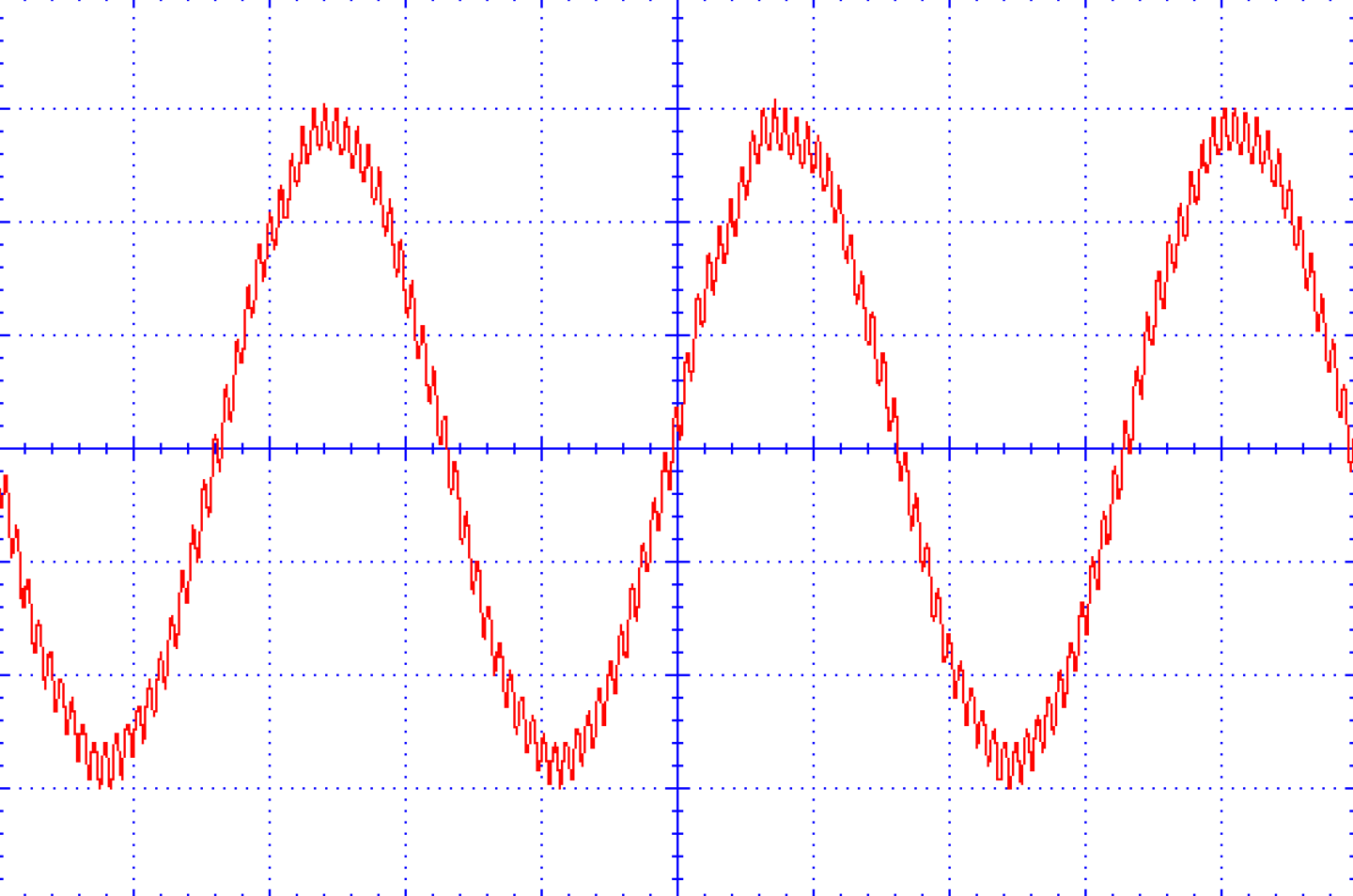
Figure 18-12. The Output of This Class-D Amplifier with a 6kHz Sinewave Input
See Also
For the TPA3122D2 datasheet see http://www.ti.com/lit/ds/symlink/tpa3122d2.pdf.