Table of Contents for
Electronics Cookbook
 Electronics Cookbook
Published by
O'Reilly Media, Inc., 2017
Electronics Cookbook
Published by
O'Reilly Media, Inc., 2017
- Cover
- nav
- Electronics Cookbook
- Electronics Cookbook
- Preface
- Theory
- Resistors
- Capacitors and Inductors
- Diodes
- Transistors and Integrated Circuits
- Switches and Relays
- Power Supplies
- Batteries
- Solar Power
- Arduino and Raspberry Pi
- Switching
- Sensors
- Motors
- LEDs and Displays
- Digital ICs
- Analog
- Operational Amplifiers
- Audio
- Radio Frequency
- Construction
- Tools
- Parts and Suppliers
- Arduino Pinouts
- Raspberry Pi Pinouts
- Units and Prefixes
- Index
- About the Author
- Colophon
Chapter 12. Sensors
12.0 Introduction
This chapter looks at sensors that convert some physical measurement such as temperature, light, or physical movement into an analog or digital electronic signal.
Many different sensors are explained, and where appropriate, ways of using them with an Arduino or Raspberry Pi are included.
12.1 Connect a Switch to an Arduino or Raspberry Pi
Solution
Connect the switch between GND and a GPIO pin set to be a digital input as shown in Figure 12-1 and enable the GPIO pin’s internal pull-up resistor.
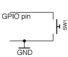
Figure 12-1. Connecting a Switch to a GPIO Pin
Your software will probably also need to “debounce” the signal from the switch.
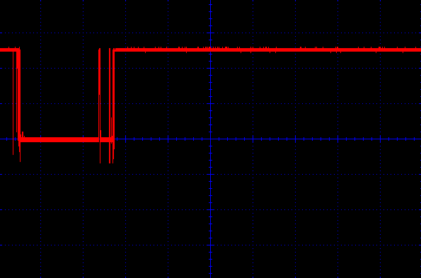
Figure 12-2. Switch Contacts Bouncing
Arduino
Here is an Arduino sketch that writes a message to the Serial Monitor whenever the switch is pressed. You can find this sketch (ch_12_switch) with the downloads for the book (see Recipe 7.2):
constintinputPin=12;voidsetup(){pinMode(inputPin,INPUT_PULLUP);Serial.begin(9600);}voidloop(){if(digitalRead(inputPin)==LOW){Serial.println("Button Pressed!");while(digitalRead(inputPin)==LOW){};delay(10);}}
The internal pull-up resistor is turned on by specifying INPUT_PULLUP in the pinMode function.
Inside the loop the inputPin is continually read until it is pressed (becomes LOW). At this point, a message is displayed in the Serial Monitor and the while loop ensures there are no further triggerings until the switch has been released. The debouncing is achieved by the 10-millisecond delay that is triggered after each button press is detected. This gives the switch contacts time to settle before they are tested again.
You can try out the example by poking the pins of a tactile push switch between GND and pin 12 on the Arduino as shown in Figure 12-3.
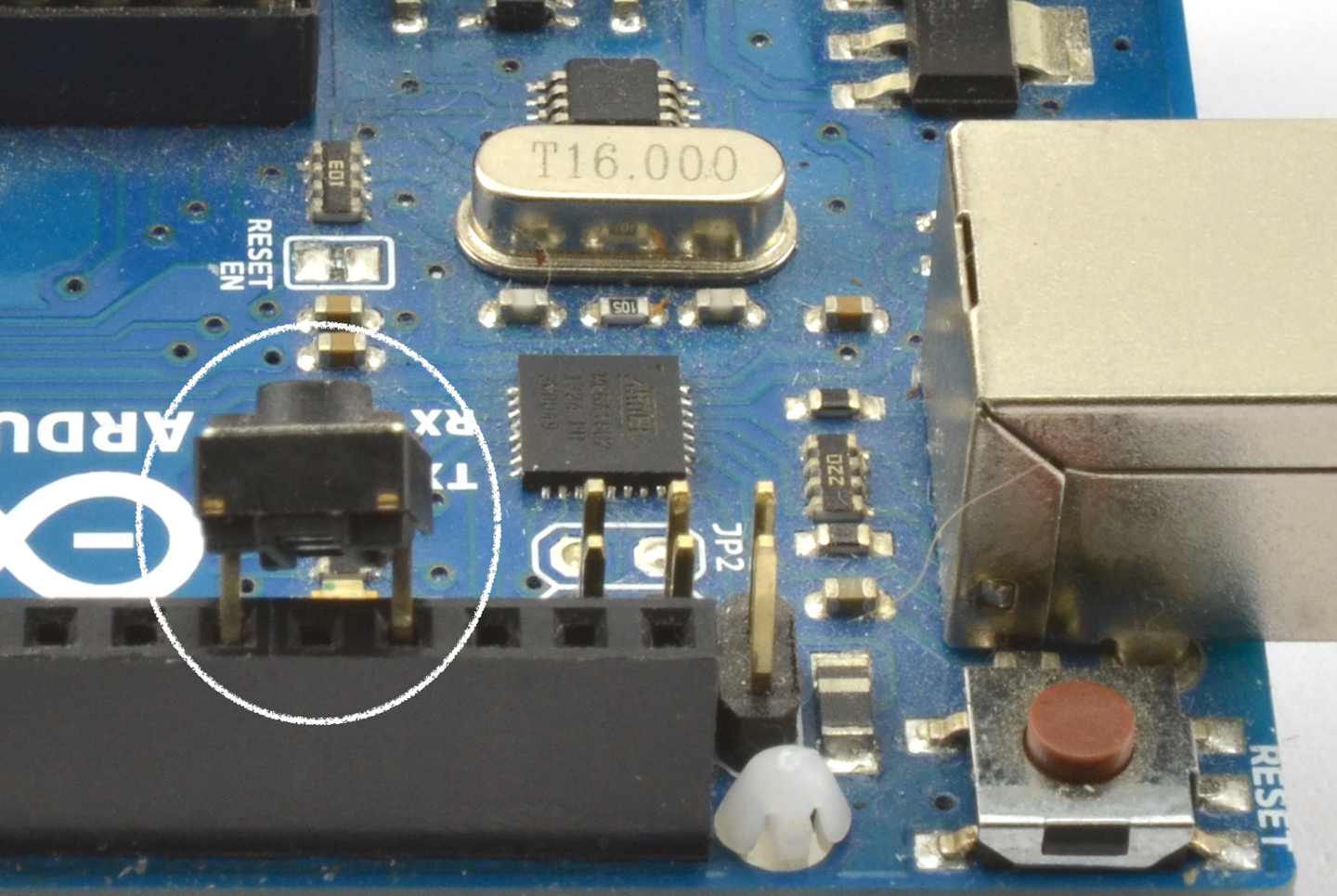
Figure 12-3. Connecting a Tactile Push Switch to an Arduino
Raspberry Pi
The equivalent code for a Raspberry Pi is listed here (ch_12_switch.py):
importRPi.GPIOasGPIOimporttimeGPIO.setmode(GPIO.BCM)input_pin=23GPIO.setup(input_pin,GPIO.IN,pull_up_down=GPIO.PUD_UP)try:try:whileTrue:ifGPIO.input(input_pin)==False:("Button Pressed!")whileGPIO.input(input_pin)==False:time.sleep(0.01)finally:("Cleaning up")GPIO.cleanup()
The logic of this program follows exactly the same pattern as for the Arduino.
Having male GPIO pins on a Raspberry Pi makes it a little more difficult to attach a switch. One way to attach the switch is to use a microswitch pushed into a pair of female-to-female jumper wires (Figure 12-4) or use a Squid Button (Figure 12-5).
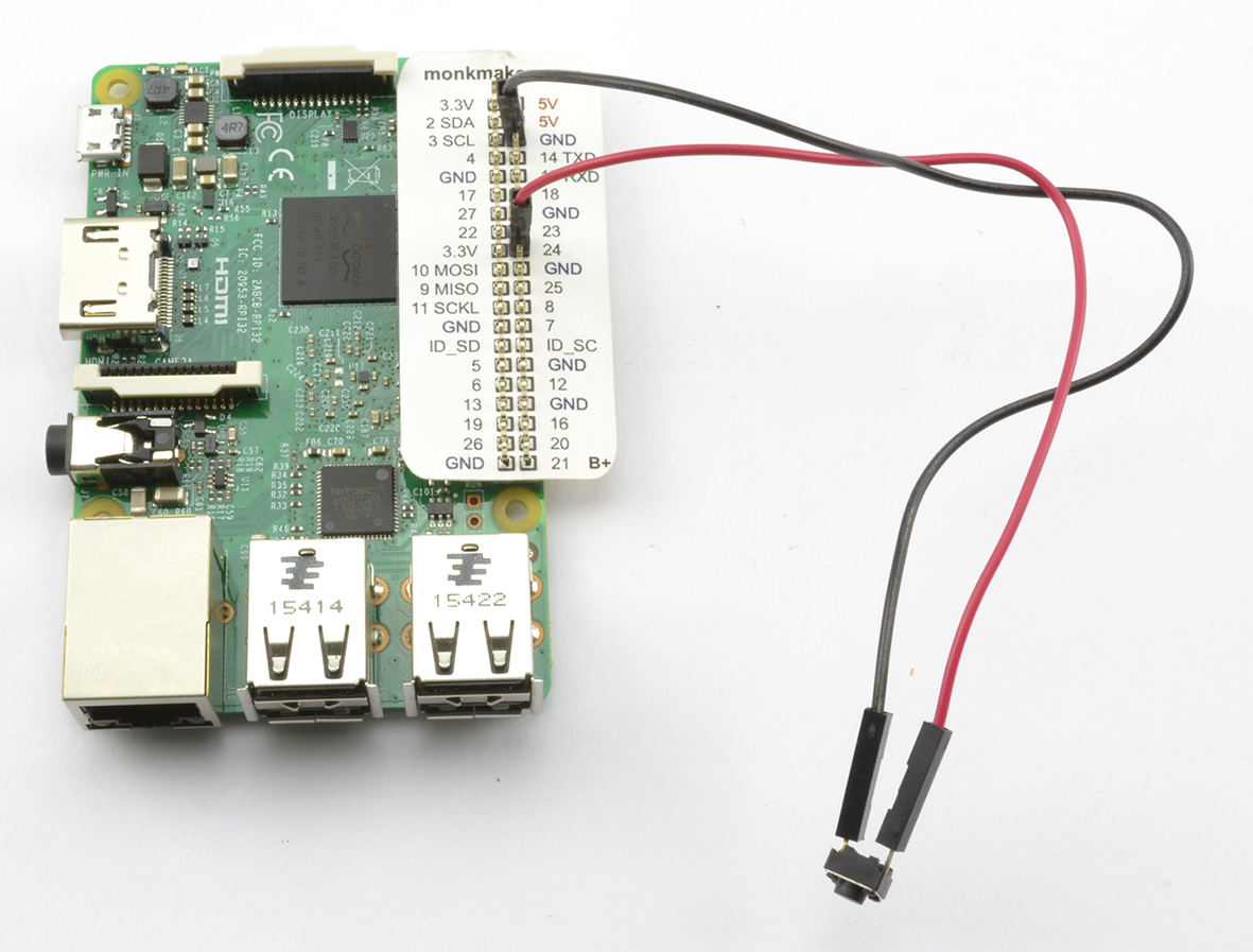
Figure 12-4. Connecting a Tactile Push Switch to a Raspberry Pi
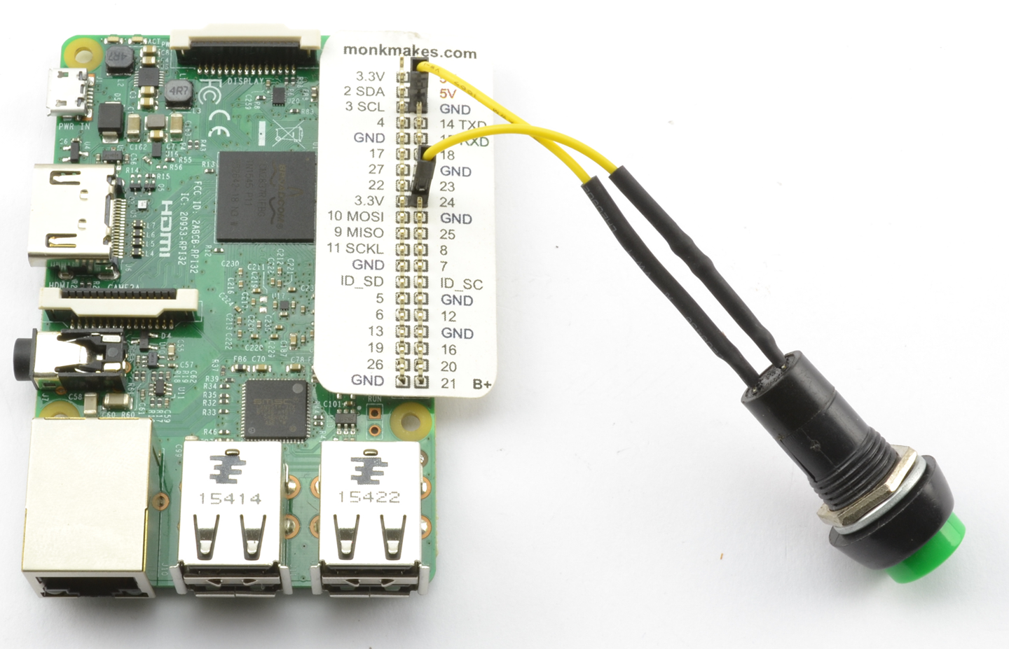
Figure 12-5. Connecting a Squid Button to a Raspberry Pi
If you plan to use a number of push switches, then whether or not you are using a Squid Button, you can use the Squid library to simplify the process of debouncing. Download and install the Squid library from https://github.com/simonmonk/squid where you will also find installation instructions. Once installed, the test program can be simplified to the following example (ch_12_switch_squid.py):
frombuttonimport*b=Button(23)whileTrue:ifb.is_pressed():("Button Pressed!")
Discussion
Microswitches (Figure 12-6) are push switches that are not designed to be directly pressed by a person, but rather have a lever attached and are used to sense physical movement such as when a linear actuator has reached its end position or as a safety interlock to make sure a microwave door is closed.
The microswitch is an SPDT device generally with closed, normally open, and common terminals (see Recipe 6.2).
Although switch using an Arduino or Raspberry Pi generally uses a pull-up resistor and switches to ground, you can also switch to the positive supply.
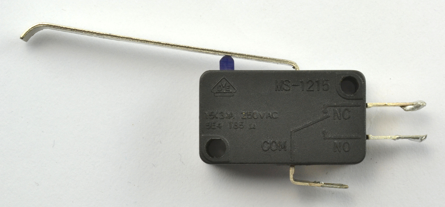
Figure 12-6. A Microswitch
To switch to the positive supply on an Arduino, you have to use an external pull-down resistor to prevent the input from floating because the Arduino does not have internal pull-down resistors on its GPIO pins (pin mode INPUT).
On the other hand, the Raspberry Pi does have internal pull-down resistors that can be enabled for a particular pin using the command:
GPIO.setup(input_pin,GPIO.IN,pull_up_down=GPIO.PUD_DOWN)
See Also
For information on the Squid Button, see https://www.monkmakes.com/squid_combo/.
Digital inputs are also described in Recipe 10.10 and Recipe 10.11.
GPIO pins are described in Recipe 10.7.
12.2 Sense Rotational Position
Solution
You’ll want a type of rotary encoder called a quadrature encoder, which behaves like a pair of switches (Figure 12-7). The sequence in which they open and close as the rotary encoder’s shaft is turned determines the direction of rotation.
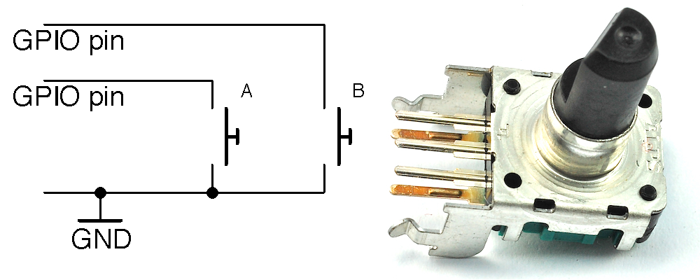
Figure 12-7. Schematic of a Rotary Encoder
A basic rotary encoder will have three pins. One for A, one for B, and a common pin. The rotary encoder shown in Figure 12-7 has two extra pins that are used for a push switch that is activated when the knob is pushed rather than turned.
When using a rotary encoder with a microcontroller or SBC, the common contact is connected to GND and the switch contacts connected to digital inputs with pull-up resistors enabled.
Arduino Software
The following Arduino sketch, which is called ch_12_quadrature, can be found with the downloads for the book (Recipe 10.12). The sketch assumes that the two switch pins are connected to pins 6 and 7:
constintaPin=6;constintbPin=7;intx=0;voidsetup(){pinMode(aPin,INPUT_PULLUP);pinMode(bPin,INPUT_PULLUP);Serial.begin(9600);}voidloop(){intchange=getEncoderTurn();if(change!=0){x+=change;Serial.println(x);}}intgetEncoderTurn(){// return -1, 0, or +1staticintoldA=0;staticintoldB=0;intresult=0;intnewA=digitalRead(aPin);intnewB=digitalRead(bPin);if(newA!=oldA||newB!=oldB){// something has changedif(oldA==0&&newA==1){result=(oldB*2-1);}elseif(oldB==0&&newB==1){result=-(oldA*2-1);}}oldA=newA;oldB=newB;returnresult;}
To avoid skipping turns, the function getEncoderTurn must be called as frequently as possible in loop.
getEncoderTurn compares the current state of the A and B switches with their states last time getEncoderTurn was called to infer whether the knob is being turned clockwise or counterclockwise, returning a value of 1 or –1, respectively. If there is no change to the values of A and B then 0 is returned.
Raspberry Pi Software
You can find the Raspberry Pi version of the rotary encoder program in the file ch_12_quadrature.py (see Recipe 10.4) and here:
importRPi.GPIOasGPIOimporttimeGPIO.setmode(GPIO.BCM)input_A=18input_B=23GPIO.setup(input_A,GPIO.IN,pull_up_down=GPIO.PUD_UP)GPIO.setup(input_B,GPIO.IN,pull_up_down=GPIO.PUD_UP)old_a=1old_b=1defget_encoder_turn():# return -1, 0, or +1globalold_a,old_bresult=0new_a=GPIO.input(input_A)new_b=GPIO.input(input_B)ifnew_a!=old_aornew_b!=old_b:ifold_a==0andnew_a==1:result=(old_b*2-1)elifold_b==0andnew_b==1:result=-(old_a*2-1)old_a,old_b=new_a,new_btime.sleep(0.001)returnresultx=0whileTrue:change=get_encoder_turn()ifchange!=0:x=x+change(x)
The test program counts up as you turn the rotary encoder clockwise, and counts down when you rotate it counterclockwise:
pi@raspberrypi ~ $ sudo python rotary_encoder.py
1
2
3
4
5
6
7
8
9
10
9
8
7
6
5
4
Discussion
Both the Arduino and Raspberry Pi versions of the software work in just the same way.
Figure 12-8 shows the sequence of pulses that you will get from the two contacts, A and B. You can see that the pattern repeats itself after four steps (hence the name quadrature encoder).
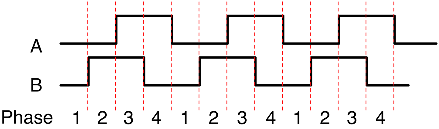
Figure 12-8. How Quadrature Encoders Work
When rotating clockwise (left to right in Figure 12-8), the sequence will be:
| Phase | A | B |
|---|---|---|
|
1 |
0 |
0 |
|
2 |
0 |
1 |
|
3 |
1 |
1 |
|
4 |
1 |
0 |
When rotating in the opposite direction, the sequence of phases will be reversed:
| Phase | A | B |
|---|---|---|
|
4 |
1 |
0 |
|
3 |
1 |
1 |
|
2 |
0 |
1 |
|
1 |
0 |
0 |
The Python program listed previously implements the algorithm for determining the rotation direction in the function get_encoder_turn. The function will return 0 (if there has been no movement), 1 for a rotation clockwise, or -1 for a rotation counterclockwise. It uses two global variables, old_a and old_b, to store the previous states of the switches A and B. By comparing them with the newly read values, it can determine (using a bit of clever logic) which direction the encoder is turning.
The sleep period of 1 millisecond is used to ensure that the next new sample does not occur too soon after the previous sample; otherwise, the transitions can give false readings (see “Contact Bounce”).
The test program should work reliably no matter how fast you twiddle the knob on the rotary encoder; however, try to avoid doing anything time consuming in the loop, or you may find that turn steps are missed.
See Also
To use a pot to sense rotation, use Recipe 12.3.
12.3 Sense Analog Input from Resistive Sensors
Solution
Put the resistive element in a voltage divider with a fixed-value resistor to convert the resistance measurement into a voltage as shown in Figure 12-9.
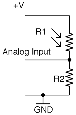
Figure 12-9. Using a Photoresistor with an Analog Input
For Raspberry Pi?
The Raspberry Pi does not have analog inputs, so to use resistive sensors with a Raspberry Pi, you either need to add analog inputs to your Raspberry Pi (see Recipe 12.4) or use the step-response method (see Recipe 12.5).
Discussion
When it comes to choosing the value of a fixed resistor, the aim should be to try and maximize the range of output voltages that will be presented to the analog input. With an Arduino Uno’s analog input range of 0 to 5V you ideally want an analog input voltage of 0 to 5V. Because a voltage divider “divides” the input voltage, you are never going to get the full voltage range as an output unless you use a higher input voltage. This introduces the potential for overvoltage at the analog input and so generally it is better to accept a slightly narrowed range rather than risk damaging your board.
Let’s take as an example a photoresistor that has a minimum resistance of 1kΩ under bright light and a resistance that rises to 1MΩ in total darkness. Assuming that you are using a 5V Arduino:

If we pick a value for the fixed resistor R2 of about 10 times of the minimum value of the photoresistor R1 then R2 would have a value of 10kΩ, so at maximum brightness:

For a resistance of 10k for the photoresistor, the Vout would be 2.5V and when the photoresistor is in complete darkness (1MΩ), the Vout would fall to 0.05V.
This would give pretty good coverage of the whole range of the photoresistor’s readings.
The following Arduino sketch assumes that R1 is a photoresistor with 1kΩ light resistance and R2 is a fixed 10kΩ resistor. The sketch calculates the resistance of R1 and displays it in the Arduino IDE’s Serial Monitor every half-second. You can find the sketch here and with the downloads for the book (see Recipe 10.2). It is called ch_12_r_adc.
constintinputPin=A0;constfloatr2=1000.0;constfloatvin=5.0;voidsetup(){pinMode(inputPin,INPUT);Serial.begin(9600);}voidloop(){intreading=analogRead(inputPin);floatvout=reading/204.6;floatr1=(r2*(vin-vout))/vout;Serial.(r1);Serial.println(" Ohms");delay(500);}
See Also
For an introduction to photoresistors, see Recipe 2.8.
For Arduino code to display such analog readings, see Recipe 10.12.
For information on voltage dividers, see Recipe 2.6.
To add analog inputs to a Raspberry Pi, see Recipe 12.4.
12.4 Add Analog Inputs to Raspberry Pi
Solution
The Raspberry Pi does not have analog inputs so connect an ADC IC to the Raspberry Pi.
Use the MCP3008 8-channel ADC chip. This chip actually has eight analog inputs, so you can connect up to eight sensors to one of these and interface to the chip using the Raspberry Pi SPI. Figure 12-10 shows the schematic for using an MCP3008 with a Raspberry Pi.
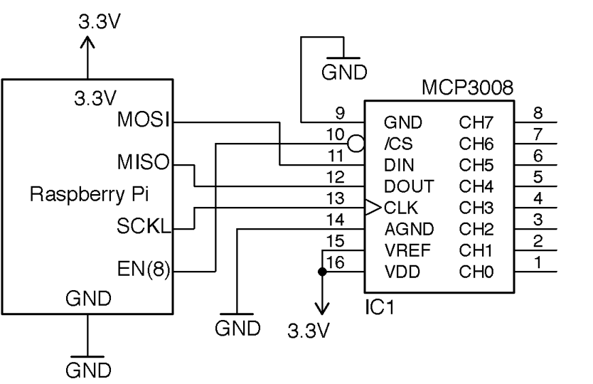
Figure 12-10. Adding Analog Inputs to a Raspberry Pi Using the MCP3008
Note that these analog inputs have a maximum input voltage of 3.3V. You will also need to make sure the SPI of the Raspberry Pi is enabled and the py-spidev Python library (included in new releases of Raspbian) is installed (Recipe 10.16).
Discussion
You can find the Raspberry Pi program to access and display the analog readings from analog channel 0 in the program ch_12_mcp3008.py (see Recipe 10.4):
importspidev,timespi=spidev.SpiDev()spi.open(0,0)defanalog_read(channel):r=spi.xfer2([1,(8+channel)<<4,0])adc_out=((r[1]&3)<<8)+r[2]returnadc_outwhileTrue:reading=analog_read(0)voltage=reading*3.3/1024("Reading=%d\tVoltage=%f"%(reading,voltage))time.sleep(1)
See Also
You can use this recipe with Recipe 12.7, Recipe 12.9, and Recipe 12.10 to read analog sensors with a Raspberry Pi.
You can use resistive sensors with a Raspberry Pi directly, without the need for an ADC IC (see Recipe 12.5).
12.5 Connect Resistive Sensors to the Raspberry Pi without an ADC
Solution
See how long it takes for a capacitor to charge the resistive sensor and use this time to calculate the resistance of the sensor.
Figure 12-11 shows the schematic for measuring resistance using nothing more than two resistors and a capacitor.
A Python library to simply read values of resistance can be downloaded from GitHub where you will also find installation instructions and documentation.
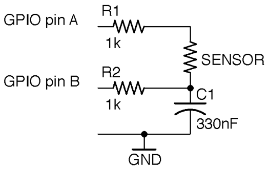
Figure 12-11. Schematic for Measuring Resistance Using the Step-response Method
The following example shows how you can use this library to measure the value of the sensor resistance when the schematic of Figure 12-11 is wired up to a Raspberry Pi with pin A connected to GPIO 18 and pin B to GPIO 23. The program is located in the examples folder of the pi_analog library and is called resistance_meter.py:
fromPiAnalogimport*importtimep=PiAnalog()whileTrue:(p.read_resistance())time.sleep(1)
To test out the method, try using a few different values of fixed resistance. You can also use different values of C1 and R1 by specifying the value of capacitance in µF and R1 in Ω in the constructor. For example, for high resistance values you might want to use a smaller capacitor (10nF) to speed up the conversion. You could use the following code:
fromPiAnalogimport*importtimep=PiAnalog(0.01,1000)whileTrue:(p.read_resistance())time.sleep(1)
Discussion
This technique relies on the ability of GPIO pins to switch between being an input and an output while the controlling program is running.
The basic steps for taking a measurement are as follows:
- Make pin A an input. Make pin B an output and LOW and wait until the capacitor is discharged.
- Make a note of the time. Make pin B an input and pin A a HIGH output. C1 will now start to charge.
- When the voltage across C1 reaches about 1.35V it will stop being a LOW input and be measured as HIGH by the GPIO pin connected to B. The time taken for this to happen is a measurement of the resistance of the sensor and R1.
See Also
The Monk Makes Electronics Starter Kit for Raspberry Pi has several projects that use this step-response method to measure temperature and light.
12.6 Measure Light Intensity
Solution
If you have an Arduino or board with analog inputs then use Recipe 12.3. If your board does not have analog inputs (say a Raspberry Pi) then use Recipe 12.4 or Recipe 12.5.
Discussion
All the preceding methods will work just fine for determining if the sensor is illuminated more brightly in one reading than in another, but obtaining a measurement in common units of light measurement is a lot trickier. Questions that make getting the light measurement difficult are:
- What frequencies of light are you talking about? All light frequencies, or just the ones the photoresistor is sensitive to?
- Do you want to measure light from a particular direction? If so, the angle of view becomes important.
Even if you answer these questions, you get into problems with the linearity of the photoresistor and will likely need to manually calibrate your meter to account for manufacturing differences in the photoresistors.
In other words, despite its apparrant simplicity making a light meter that will give you a reading in Lux or Watts per square meter is a specialist task.
See Also
For a discussion on light measurement, see https://en.wikipedia.org/wiki/Lux.
12.7 Measure Temperature on Arduino or Raspberry Pi
Solution
Use a thermistor in a voltage-divider arrangement (see Recipe 12.3), calculate the resistance, and then use the Steinhart–Hart equation to calculate the temperature.
Figure 12-12 shows the schematic for connecting a thermistor to an Arduino analog input. You should use an NTC thermistor, which has a specified nominal resistance (its resistance at 25° C) and a value of B (sometimes called beta) that determines its resistance characteristics.
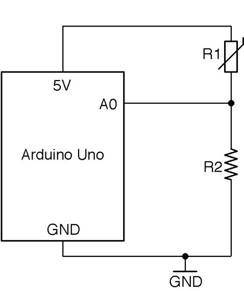
Figure 12-12. Connecting a Thermistor to an Analog Input
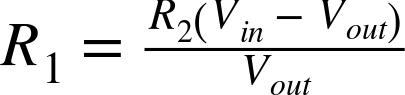
You can calculate the resistance of the thermistor R1 using the voltage-divider formula (see Recipe 2.6):

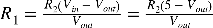
This can be rearranged to:
With a 5V Arduino and a fixed 1k resistor for R2, this gives:
The Steinhart–Hart equation states that:
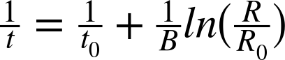
where:
- t is the temperature in Kelvin (subtract 273.15 for degrees C)
- t0 is 25° C (the standard temperature for the thermistor’s base resistance)
- B is a parameter of the thermistor that determines its sensitivity
- R is the resistance of the thermistor at temperature t
- R0 is the resistance of the thermistor at 25° C
If you plug all this math into an Arduino sketch and wire up a thermistor as shown in Figure 12-12, you end up with the following code, which can also be found with the downloads for the book in the sketch ch_12_thermistor:
constintinputPin=A0;// r2 is the bottom fixed resistor in the voltage dividerconstfloatr2=1000.0;// thermistor propertiesconstfloatB=3800.0;constfloatr0=1000.0;// other constantsconstfloatvin=5.0;constfloatt0k=273.15;constfloatt0=t0k+25;voidsetup(){pinMode(inputPin,INPUT);Serial.begin(9600);}voidloop(){intreading=analogRead(inputPin);floatvout=reading/204.6;floatr=(r2*(vin-vout))/vout;floatinv_t=1.0/t0+(1.0/B)*log(r/r0);floatt=(1.0/inv_t)-t0k;Serial.(t);Serial.println(" deg C");delay(500);}
See Also
To measure temperature using a thermistor, the step-response method, and a thermistor, see Recipe 12.8.
You can find an example of using an analog temperature-sensing IC in Recipe 12.10 and a digital device in Recipe 12.11.
12.8 Measure Temperature without an ADC on the Raspberry Pi
Solution
Use a thermistor and the pi-analog library as described in Recipe 12.5. Figure 12-13 shows the schematic for connecting a thermistor to a Raspberry Pi.
The thermistor should be an NTC device. This just means that as the temperature gets hotter the resistance gets lower. You will need to know its nominal resistance (at 25 C) and its value of B.
The pi-analog library has a program for reading the temperature in degrees C that you will find in the examples folder for the library called thermometer.py. The code for this is listed here:
fromPiAnalogimport*importtimep=PiAnalog()whileTrue:(p.read_temp_c(3800,1000))time.sleep(1)
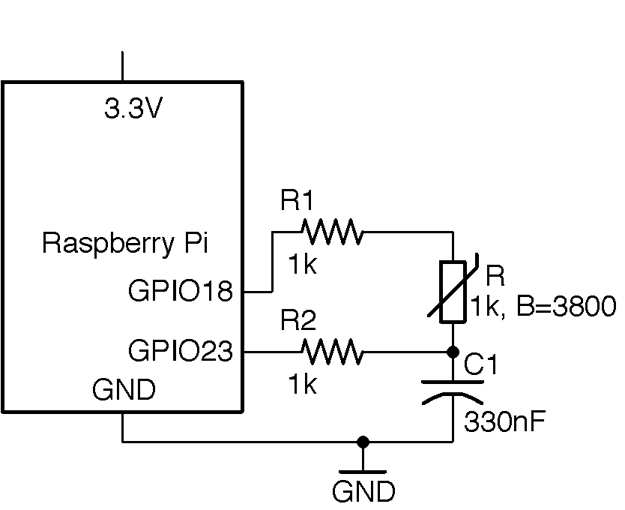
Figure 12-13. Connecting a Thermistor to a Raspberry Pi
The two parameters to read_temp_c are the thermistor’s value of B and resistance, which should be changed to suit your thermistor.
See Also
To use a thermistor with analog inputs, see Recipe 12.7.
For more information on thermistors, see https://en.wikipedia.org/wiki/Thermistor.
You can find an example of using an analog temperature-sensing IC in Recipe 12.10.
12.9 Measure Rotation Using a Potentiometer
Solution
Option 1
Use the pot as a potential divider, with the slider attached to an analog input as shown in Figure 12-14.
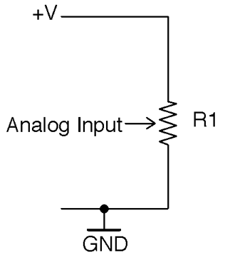
Figure 12-14. Using a Pot to Sense Rotary Position with an Analog Input
The voltage at the slider will vary from 0V to the supply voltage as you rotate the pot’s knob. You can use the same test program as Recipe 12.3 to measure the position.
Although a Raspberry Pi does not have analog inputs, you can still use this technique with a Raspberry Pi if you add an ADC chip as described in Recipe 12.4.
Option 2
For devices without an analog input, you can use the step-response method to measure the resistance between one end of the pot and the slider as shown in Figure 12-15.
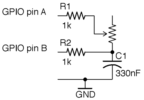
Figure 12-15. Using a Pot to Sense Rotary Position with the Step-response Method
The resistance between the slider and the end of the pot will vary from 0Ω to the maximum resistance of the pot as you rotate the pot’s knob. You can use the test program from Recipe 12.5 to measure the resistance of the pot and hence the rotary position.
Discussion
The voltage-divider approach will produce more consistent results than the step-response method.
See Also
For more on pots, see Recipe 2.3.
You can use a quadrature encoder (Recipe 12.2) to measure rotary movement.
For background on voltage dividers, see Recipe 2.6.
12.10 Measure Temperature with an Analog IC
Solution
Use a temperature-sensing IC such as the TMP36 or LM35. Figure 12-16 shows how you would connect such a device to the analog input of an Arduino. If you want to use such a sensor with a Raspberry Pi, you need to add analog inputs as described in Recipe 12.4. The TMP36 can operate from 3.3V or 5V.
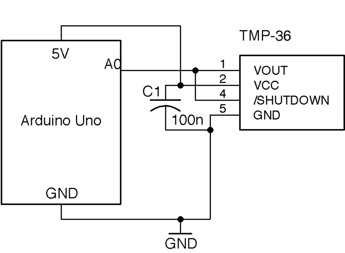
Figure 12-16. Connecting an Analog Temperature-sensing IC to an Arduino Analog Input
Note that only the SMD version of this IC has the extra SHUTDOWN pin. This can be connected to a digital output of, say, an Arduino to reduce the current consumption of the IC to 100nA when the pin is set to LOW.
C1 should be placed as close to the IC as possible.
The temperature of a TMP36 in degrees C (let’s call it t) is related to the voltage by the following formula:

where v is the output voltage of the TMP36. So, if the output voltage is 0V, the temperature is –50° C; if it is 1V, the temperature is 50° C.
Figure 12-17 shows the breadboard layout for connecting the three-pin through-hole version of the TMP36, connected to an Arduino.
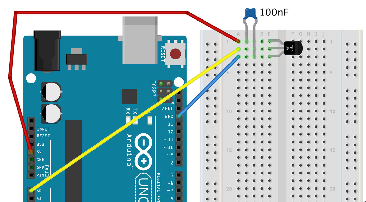
Figure 12-17. Connecting a TMP36 to an Arduino using a Solderless Breadboard
The Arduino sketch ch_12_tmp36 illustrates the use of this device. You can find this sketch here and with the downloads for the book (see Recipe 10.2):
constintinputPin=A0;constfloatsensitivity=0.01;// V/deg Cconstfloatoffset=-50.0;// deg Cvoidsetup(){pinMode(inputPin,INPUT);Serial.begin(9600);}voidloop(){intreading=analogRead(inputPin);floatvolts=reading/204.6;floatdegC=(volts/sensitivity)+offset;// float degF = degC * 9.0 / 5.0 + 32.0;Serial.println(degC);delay(500);}
The two constants sensitivity and offset allow you to use the sketch with other temperature sensors in the TMP36 family of ICs that have different sensitivity and temperature ranges.
Discussion
The TMP36 is not a very accurate device. The datasheet says ±2° C, which is fairly typical in practice and probably with similar accuracy as a thermistor (although the math is a lot easier). For greater accuracy, you should look at a digital sensor like the DS18B20 (see Recipe 12.11).
See Also
For the TMP36 datasheet, see http://bit.ly/2mbtFsg.
To measure temperature using a thermistor and an analog input, see Recipe 12.7.
You don’t have to have a microcontroller or SBC to make use of a sensor like this. For simple thermostatic applications, you can use a comparator IC (see Recipe 17.10).
12.11 Measure Temperature with a Digital IC
Solution
Use a digital temperature measurement IC like the DS18B20, which is factory calibrated to provide an accuracy of ±0.5° C.
This IC uses a 1-wire interface bus that allows up to 255 of the ICs to be connected to just one GPIO port. Figure 12-18 shows a schematic diagram for connecting a DS18B20s to an Arduino. The IC will work just as well with the 3.3V supply of a Raspberry Pi, although in the case of the Pi, GPIO pin 4 must be used as this pin is earmarked for use by the 1-wire interface.
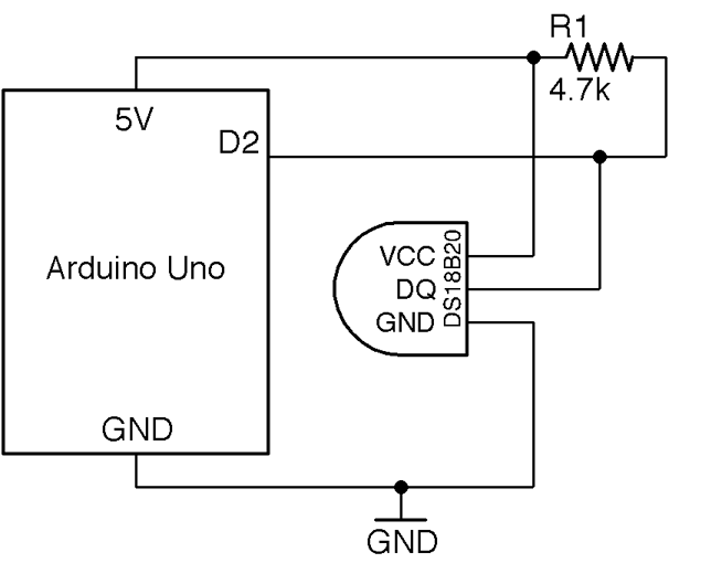
Figure 12-18. Wiring a DS18B20 Temperature Sensor to an Arduino
The 4.7kΩ external pull-up resistor is necessary for the 1-wire bus to operate reliably.
Arduino Software
Having connected the DS18B20 as shown in Figure 12-18, you will need to download the OneWire library and the DallasTemperature library. In both cases choose the Download ZIP option from the GitHub page and then add the ZIP library to your Arduino IDE from the Sketch→Include Library→Add ZIP Library menu option.
The following sketch illustrates the use of a single DS18B20, reporting the temperature to the Serial Monitor every half-second. You can find the sketch here and with the downloads for the book; it is called ch_12_ds18b20:
#include <OneWire.h>#include <DallasTemperature.h>constinttempPin=2;OneWireoneWire(tempPin);DallasTemperaturesensors(&oneWire);voidsetup(){Serial.begin(9600);sensors.begin();}voidloop(){sensors.requestTemperatures();floattemp=sensors.getTempCByIndex(0);Serial.println(temp);}
Because you can attach multiple sensors to a single GPIO pin, the getTempCByIndex function takes the number of the sensor that you wish to use (starting at 0). If you have multiple sensors you will have to use trial and error to identify which is which.
Raspberry Pi
Raspbian has support for the 1-wire interface used by the DS18B20 but you have to enable it by editing the file /boot/config.txt and adding the following line to the end of the file. Then reboot your Raspberry Pi for the change to take effect.
dtoverlay=w1-gpio
The program for this is called ch_12_ds18b20.py and can be found with the downloads for the book (see Recipe 10.4):
importglob,timebase_dir='/sys/bus/w1/devices/'device_folder=glob.glob(base_dir+'28*')[0]device_file=device_folder+'/w1_slave'defread_temp_raw():f=open(device_file,'r')lines=f.readlines()f.close()returnlinesdefread_temp():lines=read_temp_raw()whilelines[0].strip()[-3:]!='YES':time.sleep(0.2)lines=read_temp_raw()equals_pos=lines[1].find('t=')ifequals_pos!=-1:temp_string=lines[1][equals_pos+2:]temp_c=float(temp_string)/1000.0returntemp_cwhileTrue:(read_temp())time.sleep(1)
As with the Arduino version of this program, the sensor to be read is accessed by position in the line:
device_folder = glob.glob(base_dir + '28*')[0]
The interface to the DS18B20 uses a file-like structure. The file interface will always be in the folder /sys/bus/w1/devices/ and the name of the file path will start with 28, but the rest of the file path will be different for each sensor.
The code assumes that there will only be one sensor, and finds the first folder starting with 28. To use multiple sensors, use different index values inside the square brackets.
Within that folder will be a file called w1_slave, which is opened and read to find the temperature.
The sensor actually returns strings of text like this:
81 01 4b 46 7f ff 0f 10 71 : crc=71 YES
81 01 4b 46 7f ff 0f 10 71 t=24062
The code extracts the temperature part of this message. This appears after t= and is the temperature in one-thousandths of a degree Celsius.
The read_temp function calculates the temperature in degrees Celsius and returns it.
Discussion
If you want to attach multiple sensors (up to 255) you can wire them up as shown in Figure 12-19. Only the one pull-up resistor is needed, and because the sensor is digital and at a low data transmission rate, you can attach sensors to long leads with no effect on the accuracy of the reading.
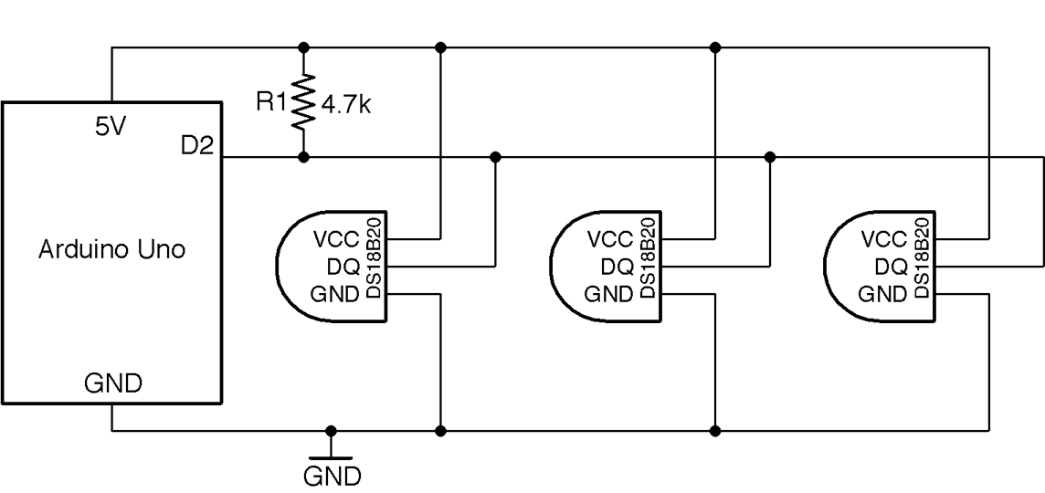
Figure 12-19. Using More than One DS18B20 Temperature Sensor
If you would rather have just two wires running to your DS18B20, you can use the device’s special parasitic power feature. In essence, it harvests energy from the data line, storing it temporarily in capacitors inside the IC. In parctical terms, the 3-wire method will allow you to use longer wires to your sensor and will be more reliable, but see the IC’s datasheet if you wish to use this mode.
If you plan to deploy your sensor somewhere wet, use encapsulated DS18B20 sensors that are enclosed in a waterproof case that can be found on eBay.
See Also
The DS18B20 datasheet can be found here: http://bit.ly/2mTPyuu
To measure temperature with a thermistor, see Recipe 12.7 and Recipe 12.8.
To measure temperature with the TMP36 analog temperature-sensing IC, see Recipe 12.10.
12.12 Measure Humidity
Solution
Use a DHT11 humidity and temperature sensor, which has a serial output that does not really conform to any bus standard like 1-wire, I2C, or SPI. However, libraries for both Arduino and Raspberry Pi are available for it.
Figure 12-20 shows how it should be connected to an Arduino. When used with a Raspberry Pi, the pin labeled VDD (voltage drain drain) should be connected to 3.3V and the DATA pin to GPIO 4.
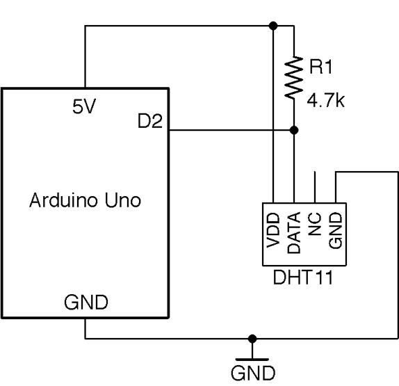
Figure 12-20. Connecting a DHT11 to an Arduino Uno
When connecting to a Raspberry Pi, use the 3.3V power connector not the 5V one and connect the data pin of the DHT11 to GPIO4.
Arduino Software
The Arduino sketch can be found with the downloads for the book (Recipe 10.2) and is called ch_12_dht11. The sketch requires the Arduino SimpleDHT library to be installed. You can do this from the Arduino Library Manager by using the option Sketch→Include Library→Manage Libraries, searching for SimpleDHT, and then clicking the Install button next to the library.
#include <SimpleDHT.h>constintpinDHT11=2;SimpleDHT11dht11;voidsetup(){Serial.begin(9600);}voidloop(){bytetemp;bytehumidity;dht11.read(pinDHT11,&temp,&humidity,NULL);Serial.(temp);Serial.(" C, ");Serial.(humidity);Serial.println(" %");delay(1000);}
The call to dht11.read is a little unusual because it passes the variables temp and humidity with an & in front of them to indicate that they can be changed within the read function. In this way, after the read function has finished executing, temp and humidity will have updated values.
Raspberry Pi Software
The Raspberry Pi code for this sensor requires an Adafruit library to be installed using the following commands:
$ git clone https://github.com/adafruit/Adafruit_Python_DHT.git
$ cd Adafruit_Python_DHT
$ sudo python setup.py install
The program itself can be found with the downloads for the book (Recipe 10.4) and is called ch_12_dht11.py:
importtime,Adafruit_DHTsensor_pin=4sensor_type=Adafruit_DHT.DHT11whileTrue:humidity,temp=Adafruit_DHT.read_retry(sensor_type,sensor_pin)(str(temp)+" C "+str(humidity)+" %")time.sleep(1)
Discussion
The DHT11 is the cheapest and most common series of similar sensors with different accuracies. For better quality results use the DHT22.
See Also
Other recipes for measuring temperature are Recipe 12.7, Recipe 12.8, Recipe 12.10, and Recipe 12.11.
12.13 Measure Distance
Solution
For distances between 4 inches (10cm) and 6 feet (2m) use an HC-SR04 ultrasonic rangefinder module.
Figure 12-21 shows how the rangefinder is connected to an Arduino. Interfacing to it requires one pin of the Arduino to act as a digital output (connected to TRIG) and one as a digital input (connected to ECHO).
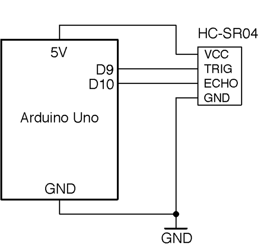
Figure 12-21. Connecting an HC-SR04 Rangefinder to an Arduino
The TRIG pin causes the HC-SR04 to emit a pulse of ultrasound at 40kHz and the ECHO pin goes high when the reflected sound wave is received. The time taken for this to happen is an indication of the distance from the sensor to the object.
To connect the rangefinder to a Raspberry Pi, the output voltage of the ECHO pin of the rangefinder needs to be reduced to 3.3V. This can be done with a simple level converter using a pair of resistors as a voltage divider. The schematic for this is shown in Figure 12-22.
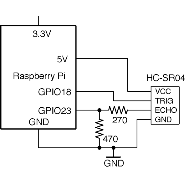
Figure 12-22. Connecting an HC-SR04 Rangefinder to a Raspberry Pi
For more information on level conversion, see Recipe 10.17.
Arduino Software
An Arduino sketch (ch_12_rangefinder) for rangefinding can be found with the downloads for the book (see Recipe 10.2):
constinttrigPin=9;constintechoPin=10;voidsetup(){pinMode(trigPin,OUTPUT);pinMode(echoPin,INPUT);Serial.begin(9600);}voidloop(){floatcm=takeSounding();Serial.(int(cm));Serial.(" cm ");intinches=int(cm/2.5);Serial.(inches);Serial.println(" inches");delay(500);}floattakeSounding(){digitalWrite(trigPin,HIGH);delayMicroseconds(10);// 10us trigger pulsedigitalWrite(trigPin,LOW);delayMicroseconds(200);// ingore echos while sending 200uslongduration=pulseIn(echoPin,HIGH,100000)+200;floatdistance=duration/29.0/2.0;returndistance;}
All the action takes place in the takeSounding function. First, a 10µs pulse is sent to the TRIG pin of the rangefinder resulting in a burst of eight cycles of 40kHz ultrasound. The 200µs delay allows time for this burst to complete before measuring the time taken until an echo is received.
The distance is calculated using the speed of sound (29cm/µs.) The value is divided by 2 because the time taken is for both the outward and return journey of the sound signal.
Raspberry Pi Software
The Raspberry Pi program can be found in the file ch_12_rangefinder.py with the downloads for the book (see Recipe 10.4):
importRPi.GPIOasGPIOimporttimetrigger_pin=18echo_pin=23# USE LEVEL CONVERTER 5V->3.3VGPIO.setmode(GPIO.BCM)GPIO.setup(trigger_pin,GPIO.OUT)GPIO.setup(echo_pin,GPIO.IN)deftime_to_echo(timeout):t0=time.time()whileGPIO.input(echo_pin)==Falseandtime.time()<(t0+timeout):passt0=time.time()whileGPIO.input(echo_pin)==Trueandtime.time()<(t0+timeout):passreturntime.time()-t0defget_distance():GPIO.output(trigger_pin,True)time.sleep(0.00001)# 10usGPIO.output(trigger_pin,False)time.sleep(0.0002)# 200uspulse_len=time_to_echo(1)distance_cm=pulse_len/0.000058distance_in=distance_cm/2.5return(distance_cm,distance_in)whileTrue:("cm=%f\tinches=%f"%get_distance())time.sleep(1)
Discussion
The HC-SR04 rangefinders are not particularly accurate, especially when used with a Raspberry Pi, where the operating system will sometimes increase the timing readings for the echo.
Another unwanted influence on the readings comes from variations in the speed of sound. This changes a little both with temperature and humidity.
See Also
The datasheet for the HC-SR04 module can be found here: http://bit.ly/2mTOPtn.