Table of Contents for
Electronics Cookbook
 Electronics Cookbook
Published by
O'Reilly Media, Inc., 2017
Electronics Cookbook
Published by
O'Reilly Media, Inc., 2017
- Cover
- nav
- Electronics Cookbook
- Electronics Cookbook
- Preface
- Theory
- Resistors
- Capacitors and Inductors
- Diodes
- Transistors and Integrated Circuits
- Switches and Relays
- Power Supplies
- Batteries
- Solar Power
- Arduino and Raspberry Pi
- Switching
- Sensors
- Motors
- LEDs and Displays
- Digital ICs
- Analog
- Operational Amplifiers
- Audio
- Radio Frequency
- Construction
- Tools
- Parts and Suppliers
- Arduino Pinouts
- Raspberry Pi Pinouts
- Units and Prefixes
- Index
- About the Author
- Colophon
Chapter 7. Power Supplies
7.0 Introduction
Anything electronic needs a source of power. This may be as simple as a battery, but often will involve reducing high-voltage AC to the normal 1–12V DC that most electronics use.
Sometimes you need to generate higher voltages from a low-voltage battery. This may be stepping up the supply from a single 1.5V AA battery to a 6 or 9V, or it may be to generate much higher voltages for applications such as the 400V to 1.5kV supply needed by Geiger-Müller tubes.
The ultimate high-voltage power supply is a solid-state Tesla coil (see Recipe 7.15).
This is the first chapter where you will encounter a fair selection of ICs. When using an IC that you are not familiar with, your first port of call should be its datasheet. It will not only tell you how to avoid destroying it (by making sure you do not exceed its maximum ratings) but will also tell you how it behaves and if you are lucky will often include “reference designs” that are complete circuits that use the chip in a practical situation. These designs are developed by the chip manufacturer to show you how to use the IC, and many of the recipes in this chapter start from such reference designs.
If the datasheet for the IC does not include such useful designs, then the next thing to search for is “application notes” for the IC. This will often expand the rather terse and scientific-looking datasheet into practical circuits using the IC.
7.1 Convert AC to AC
Solution
Use a transformer (see Recipe 3.9).
When buying a transformer designed for 60Hz AC, you will often find the windings in an arrangement something like the one shown in Figure 7-1.
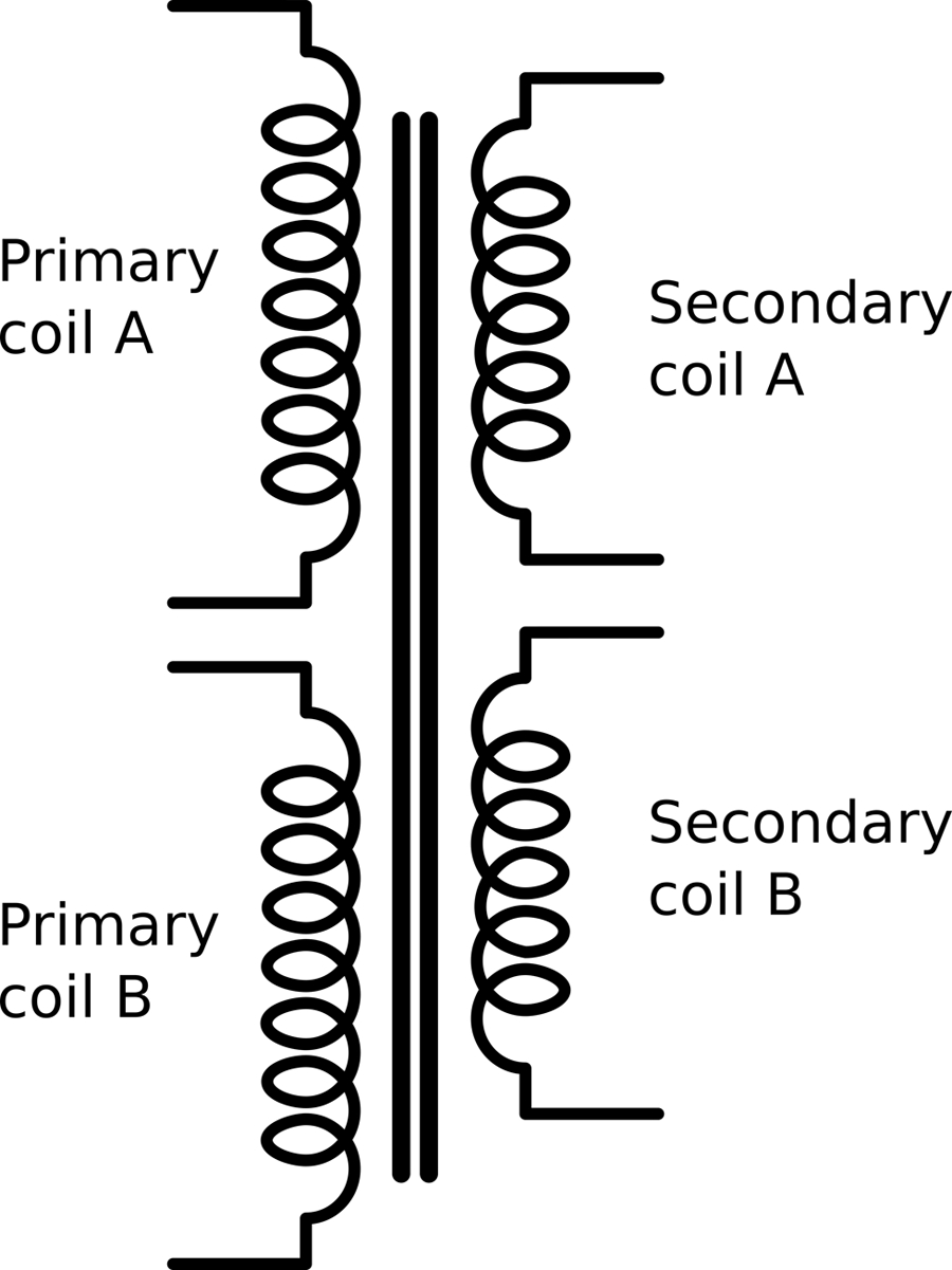
Figure 7-1. A Transformer Designed for AC
This has two identical primary coils and two identical secondary coils, all wound on the same former (laminated iron frame). This allows some flexibility in how the transformer is used. For example, US electricity is 110V whereas much of the world uses 220V AC. If you are designing a product and need the same low-voltage AC output whether the input is 100V or 220V, then two primary coils allow you to do this if you power the primaries in parallel for 110V and series for 220V.
The dual secondaries provide similar flexibility to wire in series for double the output voltage.
Discussion
Transformers are only rated to handle a certain amount of power. The resistance of the windings causes them to heat as current flows through them, and if things get too hot the insulation on the wire will break down and the transformer will fail.
A transformer will normally be rated as so many VA (volt amps). For most loads connected to a transformer 1VA is the same as 1Watt, but if large inductive loads like motors are being driven, then the current and voltage become out of phase and the apparent power will be lower than the VA rating.
See Also
For an introduction to transformers, see Recipe 3.9.
Reducing the AC voltage is often the first step in making an unregulated power supply, which is the topic of Recipe 7.2.
7.2 Convert AC to DC (Quick and Dirty)
Solution
Use an AC step-down transformer (see Recipe 7.1) and then rectify and smooth the output.
Figure 7-2 shows one schematic for the simplest method of achieving this.
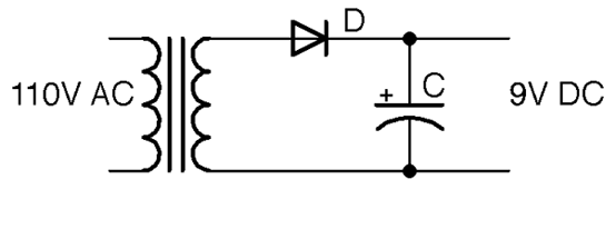
Figure 7-2. A Basic Unregulated AC-to-DC Power Supply
The output voltage in Figure 7-2 is shown as 9V. This will be 1.42 (square root of 2) of the stated output voltage of the transformer.
The diode D rectifies the low-voltage AC from the transformer (see Recipe 4.1). The capacitor C then smooths this out to a constant DC that theoretically will be the peak voltage from the cathode of the diode. The diode will prevent the capacitor from discharging back through the transformer and so once it is at the peak voltage it will stay there.
Discussion
The schematic of Figure 7-2 is missing any kind of load. The capacitor is being charged to the peak voltage, but nothing is using that charge. When you add a load to the output as shown in Figure 7-3 the capacitor will still be receiving its kicks of voltage from the diode and transformer, but now it will be discharging through the load at the same time.
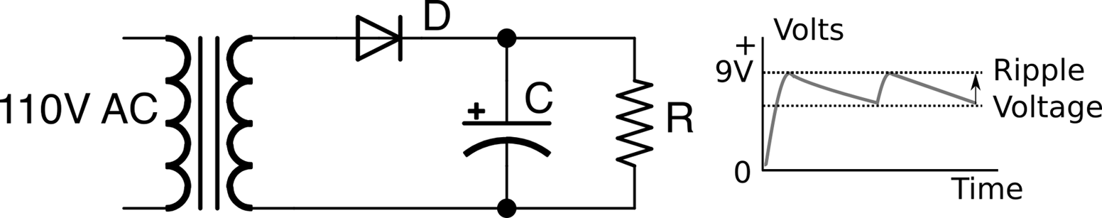
Figure 7-3. A Basic Unregulated AC-to-DC Power Supply
When using power supplies you will hear the use of the word “load,” which is the thing that is being powered by the power supply. When thinking about how the power supply will operate, you can just think of this load as a resistance. In Figure 7-3 the load is represented by R.
The characteristic voltage drop during each cycle due to the load discharging C is called the ripple voltage.
The size of this ripple voltage can be calculated from the load current and also from the size of the capacitor according to this formula:
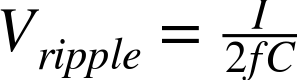
where I is the current in amps, f is the AC frequency (60Hz), and C is the capacitance in Farads.
As an example, if the load current is 100mA, a 1000µF capacitor would reduce the ripple voltage to:

Notice that the ripple voltage is proportional to the load current, so in the preceding example, a current of 1A would result in a ripple voltage of 8.3V!
This state of affairs can be improved by using a full-wave rectifier as described in Recipe 7.3, which effectively doubles the frequency f in the preceding formula, halving the ripple voltage.
See Also
For full-wave rectification, see Recipe 7.3.
7.3 Convert AC to DC with Less Ripple
Problem
The half-wave rectification of Recipe 7.2 is not very efficient. You want to reduce the ripple voltage by using full-wave rectification.
Solution
There are two solutions to this:
- If you have a center-tapped or dual secondary transformer, you just need two diodes for full-wave rectification.
- If you only have a single secondary winding, you can use four diodes as a bridge rectifier.
Full-wave rectification with dual windings
Figure 7-4 shows how you can make use of both the positive and negative halves of the AC cycle.
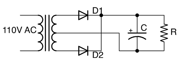
Figure 7-4. Full-wave Rectification using Dual Secondary Windings
The secondary windings are in serial, with the central connection between the windings becoming the ground of the DC output. When the end of the winding connected to D1 is at its maximum, the end of the winding connected to D2 will be at its minimum (greatest negative value). D1 and D2 will take it in turn to provide positive voltage to the capacitor and the whole AC cycle can contribute to charging the capacitor. Figure 7-5 shows the full-wave rectified output before it is smoothed by the capacitor. It is as if the negative cycles are being reversed.
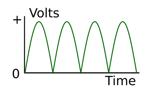
Figure 7-5. Full-wave Rectification
Using a Bridge Rectifier
If you only have a single secondary winding, then you can still achieve full-wave rectification by using an arrangement of four diodes called a bridge rectifier. Figure 7-6 shows an unregulated DC power supply using a bridge rectifier.
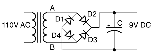
Figure 7-6. Using a bridge rectifier
To understand how this works, imagine that point A is positive and B is negative. This will allow current to flow from A through D2 to charge the capacitor. If there is a load on the power supply, then the current from the negative side of the DC output will be able to flow back through D4 to B.
When the AC cycle flips polarity and it is B that is positive and A negative, then the positive DC output is supplied through D3 and returns to A through D1.
Discussion
In Recipe 7.2 you saw how the ripple voltage halves if you use full-wave rectification rather than half-wave. The ripple voltage can be reduced by using very large capacitors, but in most circumstances it is better to use a regulated power supply as described in Recipe 7.4 or a switched mode power supply (SMPS), as discussed in Recipe 7.8.
You can buy a bridge rectifier as a single component that contains the four diodes wired up in a bridge configuration. This simplifies the wiring of your power supply as the bridge rectifier will have four terminals: two marked with a ~ to indicate AC input as well as + and – terminals for the rectified output.
See Also
To learn about half-wave rectification, see Recipe 4.1 and Recipe 7.2.
7.4 Convert AC to Regulated DC
Solution
Use a linear voltage regulator IC after your unregulated DC power supply.
Figure 7-7 shows such a circuit. As you can see, the first stage of the project is just an unregulated power supply.
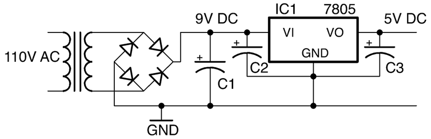
Figure 7-7. A Regulated DC Power Supply
A linear voltage regulator IC such as the very common 7805 regulator has three pins:
- GND
- Vin—unregulated DC input
- Vout—regulated DC output
In the case of the 7805, the output voltage is fixed at 5V, so as long as the input voltage is above about 7V the output will not have any significant ripple voltage (because the regulator chip needs about 2V more than its output voltage of 5V to successfully regulate the voltage).
At first sight, since C1 and C2 are in parallel, it is not immediately obvious why you would need both. However, the reason is that C1 will be a large electrolytic capacitor (470µF or more) and C2 will be a smaller MLC (typically 330nF) with a low ESR that should be positioned as close as possible to the voltage regulator. C2 along with C3, which is typically 100nF, are required by the voltage regulator IC to ensure that the regulation remains stable.
Discussion
In selecting values for C2 and C3, it is best to consult the datasheet for the voltage-regulator IC that you are using. This will normally specify values for the capacitors as well as tell you other important properties of the voltage regulator such as:
- Maximum current that can be drawn from the output (1A for a 7805)
- Maximum input voltage (35V for a 7805)
- Dropout voltage—the number of volts by which the input should exceed the output for normal operation (2V for a 7805)
Some linear voltage regulators are described as low-dropout (LDO). These have a much smaller dropout voltage than the 2V of the 7805. Some only need as little as 150mV more at the input than the output. If the input voltage of the regulator does fall below the dropout voltage, the output voltage will gradually decrease as the input voltage decreases. These regulators such as the LM2937, which has a dropout of 0.5V, are great if your input voltage is unavoidably close to the desired output. Perhaps you have a 6V battery and require a 5V output. Keeping the input voltage close to the output voltage also helps to reduce the heat generated by the regulator.
Voltage regulators are available in various packages from tiny surface-mount devices to larger packages such as the TO-220 package of the 7805, which are designed to be bolted to a heatsink for higher current use.
Most voltage regulators including the 7805 have protection circuitry that monitors the device’s temperature and if it gets too hot, it drops the output voltage and therefore limits the output current so that the device is not destroyed by the heat. Voltage regulators also have a mounting hole designed to be attached to a heatsink. This is not needed for low currents, but as the current gets higher a heatsink (see Recipe 20.7) will become necessary.
The 05 part of the 7805 refers to the output voltage and, as you might expect, you can also find 7806, 7809, 7812, and other voltages up to 24V. There is also a parallel 79XX range of negative voltage regulators should you need to provide regulated positive and negative power supplies as you do for some analog applications.
The 78LXX range of regulators are a lower-power (and smaller package) version of the 78XX regulators.
See Also
You can find the datasheet for the 7805 here: https://www.fairchildsemi.com/datasheets/LM/LM7805.pdf.
These days, most regulated AC-to-DC power supplies use SMPS design (Recipe 7.8).
7.5 Converting AC to Variable DC
Solution
Use an adjustable voltage regulator like the LM317.
Figure 7-8 shows a typical schematic for a variable output voltage regulator using the LM317.
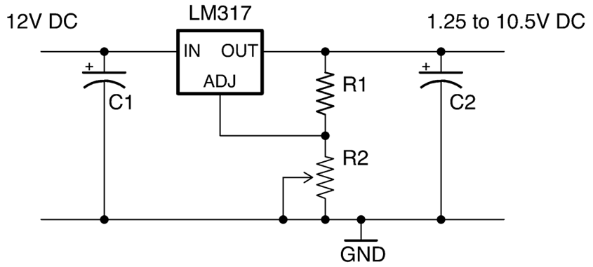
Figure 7-8. Using an LM317 Voltage Regulator
The output voltage of the LM317 varies according to the formula:
This only holds true as long as R2 is relatively low resistance (less than 10kΩ).
So, if R1 is 270Ω and R2 is a 2kΩ pot, then at one end of the pot’s travel, the output voltage will be:

When the pot’s knob is rotated fully the other way, the output voltage will be:

Discussion
As R2 increases, the output voltage also increases, but as with a fixed-output regulator, the regulator requires some spare voltage to do the regulating with. In the case of the LM317, this is about 1.5V less than the input voltage.
Adjustable voltage regulators like the LM317 are available in a number of different-sized packages and able to handle different amounts of current before their temperature-protection circuitry kicks in to prevent damage to the IC.
See Also
You can find the datasheet for the LM317 here: http://www.ti.com/lit/ds/symlink/lm317.pdf.
To use an LM317 as a current regulator, see Recipe 7.7.
7.6 Regulate Voltage from a Battery Source
Solution
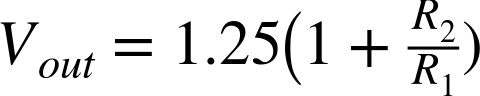
Use a fixed linear voltage regulator as shown in Figure 7-9.
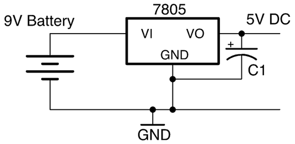
Figure 7-9. Using a Voltage Regulator with a Battery
Discussion
New batteries have a voltage that often starts a little higher than the rated voltage (perhaps 9.5V for a 9V battery). This voltage drops as the battery is used. A 9V battery will quickly fall to 8V and will probably only provide useful power until it falls to perhaps 7.5V as it’s almost completely empty.
A voltage regulator can be used to provide constant output voltage during the lifetime of the battery and also to reduce voltage to a specific voltage needed for a microcontroller (usually 3.3V or 5V).
Unlike the transformer-based DC supply of Recipe 7.4 a battery does not suffer from ripple voltage, so the capacitor at the input to the voltage regulator can be omitted. However, the capacitor at the output is still needed in most applications as the load is likely to vary a lot and could cause instability in the regulator.
See Also
For more information on batteries, see Chapter 8.
7.7 Make a Constant-Current Power Supply
Solution
Use an LM317 voltage regulator configured in constant-current mode as shown in Figure 7-10.
Figure 7-10. Using an LM317 as a Constant-Current Source
For the LM317 chip, the output current is set by the value of R1 using the formula:
So, to limit the current to a maximum of 100mA the resistor value would be chosen using:
Discussion
This circuit will automatically raise and lower the output voltage to keep the current at the desired level.
See Also
To see this circuit limit the power to a high-power LED, see Recipe 14.2.
7.8 Regulate DC Voltage Efficiently
Solution
Use a switching voltage-regulator IC like the one in the schematic shown in Figure 7-11.
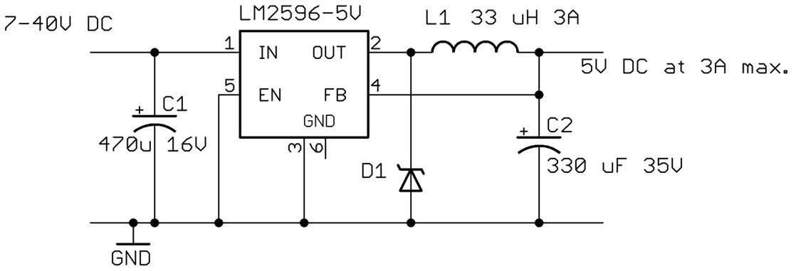
Figure 7-11. A Switching Voltage Regulator Using the LM2596
The LM2596 can provide a regulated power supply at 3A without needing a heatsink.
The FB (feedback) pin allows the regulator to monitor the output voltage and adjust the width of the pulses to keep the voltage constant. The EN (enable) pin can be used to turn the IC on and off.
Discussion
Linear regulators as described in Recipe 7.4, Recipe 7.5, and Recipe 7.6 suffer from the disadvantage that they simply burn off the excess voltage as heat, which means they get hot and also waste energy.
Switching regulator designs such as the buck regulator shown in Figure 7-11 operate at 85% efficiency almost independently of the input voltage. By comparison, a linear regulator with a high input voltage and a low output voltage may only have an efficiency of perhaps 20 to 60%.
In a similar manner to PWM (see Recipe 10.8) a buck converter uses a transistor to switch power to an inductor that stores the energy of each pulse at a high frequency (150kHz for the LM2596). The longer the pulse the higher the output voltage. A feed-back mechanism changes the pulse length in response to the output voltage, ensuring a constant output.
It makes little sense to design a switching power supply from discrete components when there are ICs like the LM2596 that will do the whole thing so well.
There are many switching voltage-regulator ICs available and generally their datasheet will include a well-designed application circuit and sometimes even a circuit board layout.
If you are making a one-off project, then it is worth considering buying a ready-made switching-regulator module, either from eBay or suppliers like Adadruit and Sparkfun that specialize in modules.
See Also
You can find the datasheet for the LM2596 here: http://bit.ly/2lOLtHc.
7.9 Convert a Lower DC Voltage to a Higher DC Voltage
Solution
Use a boost-converter IC as the basis for a design like the one shown in Figure 7-12.
This design will produce an output voltage of 5V from an input voltage of between 0.9V and 5V at 90% efficiency.
The SW (switch) output of the IC is used to send pulses of current through the inductor L1 generating high-voltage spikes that charge C1. The output VOUT is monitored through the FB (feedback) pin via the voltage divider formed by R1 and R2 that sets the output voltage.
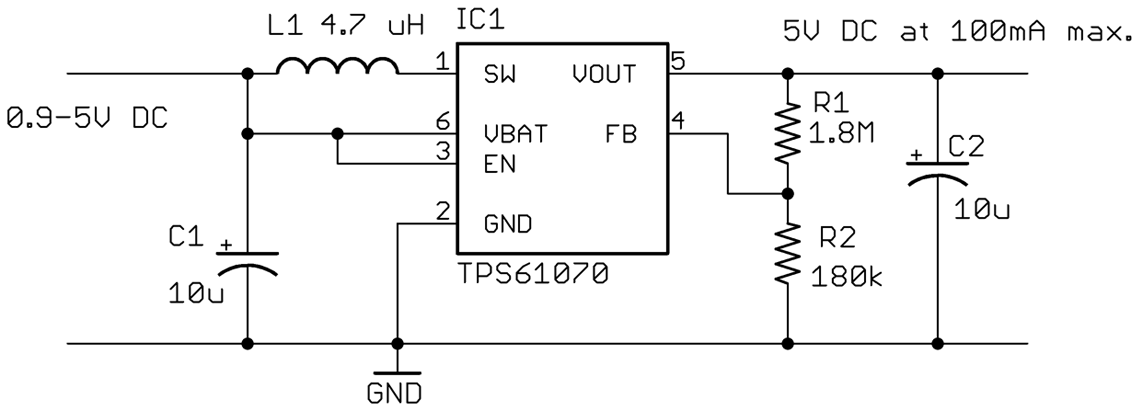
Figure 7-12. Using a TPS61070 Boost Converter
Discussion
The potential divider formed by R1 and R2 sets the output voltage. The value of R2 should be fixed at 180kΩ and the value of R1 calculated using the formula:

There are many similar boost-converter ICs available. In all cases, read the datasheet carefully as it will include a reference design and guides for finding the correct values for external components.
See Also
The datasheet for the TPS61070 can be found here: http://www.ti.com/lit/ds/symlink/tps61070.pdf.
7.10 Convert DC to AC
Solution
Use an inverter. These devices use an oscillator to drive a transformer and generate high-voltage AC from low-voltage DC.
High-Voltage AC
An inverter generates high-voltage AC, high enough voltage and current to stop your heart. So, do not attempt to make an inverter unless you are absolutely certain you have the knowledge and skills to do so safely.
Generating 110V from a low-voltage source (say a 12V car battery) is in theory very simple, but unless you really want to make such a thing yourself, it is generally cheaper and safer to buy a ready-made inverter product.
For more information on working with high voltages, see Recipe 21.12.
Discussion
If you really do wish to make yourself an inverter, Figure 7-13 shows a typical schematic.
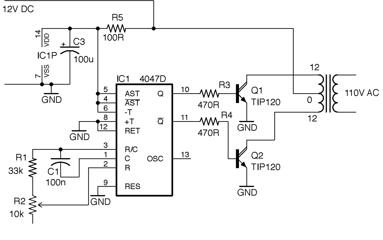
Figure 7-13. An Inverter Schematic
This design uses the CD4047 timer IC as an oscillator. This IC provides a similar function to the much more famous 555 timer (see Recipe 7.13, Recipe 7.14, and several recipes in Chapter 16) but has the advantage that it has both normal and inverted outputs. These two ouputs each drive an NPN Darlington power transistor to energize one half of the primary coil in turn.
The transformer used here is the kind used in recipes such as Recipe 7.1 to step down an AC voltage, but in this case, it will be used to step the voltage up. The windings that would normally be used as the secondary side of the transformer will be driven by the transistors and the output from the transformer will be taken from the coil that would normally have been connected to AC.
To drive the circuit from 12V DC at 60Hz to produce a 110V AC output you need a transformer with a 12-0-12V secondary and a 110V primary.
The power to the CD4047 is supplied through a 100Ω resistor (R5) and a 100µF decoupling capacitor (C3; see Recipe 15.1) across the IC’s power supply. These reduce noise on the power supply to the CD4047.
Figure 7-14 shows the inverter built on a breadboard. This arrangement is fine as a first prototype, but in practice the design would be better built onto a circuit board and the power transistors attached to sizeable heatsinks (Recipe 20.7). It would also be wise to include a fuse in the 12V supply line to limit the current to a value that the transistors can handle, otherwise the transistors could overheat and die.
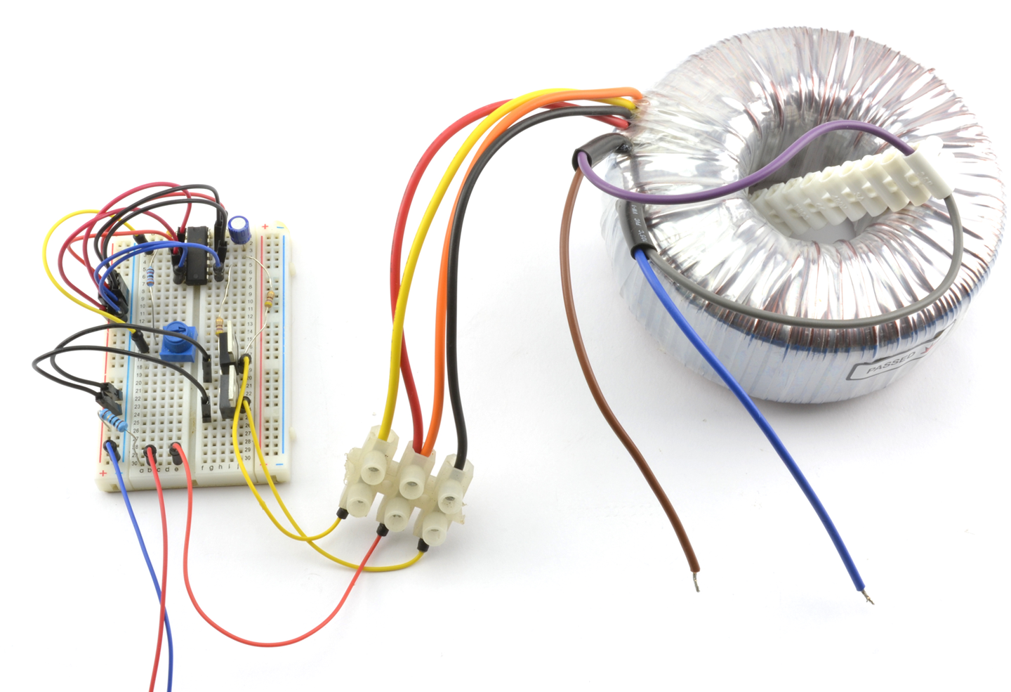
Figure 7-14. An Invertor Circuit Built on Breadboard
The transformer used is a toroidal type that I had available, but any type of transformer can be used.
See Also
For information on using a 4047 IC see its datasheet.
To learn about fuses, see Recipe 7.16.
To build circuits using a solderless breadboard, see Recipe 20.1.
See Recipe 3.9 for more information on transformers.
7.11 Power a Project from 110 or 220V AC
Problem
You want to power your project from 110V or 220V AC supply efficiently, without using a large transformer like the one used in Recipe 7.2.
Solution
Designing SMPSs intended for high-voltage use is a specialized and potentially dangerous activity. Aside from the always present danger of electric shock, a poorly designed SMPS can easily overheat and become a fire hazard.
For these reasons, I strongly suggest that when you need to power a project from AC, use a ready-made commercial SMPS “wall wart” power adapter and fit a DC barrel jack socket to your project. These sealed adapters are readily available and made in such quantities that they will almost certainly be cheaper to buy than to make.
Discussion
It is interesting to see how these power supplies work. Figure 7-15 shows how such a power supply can achieve the same power output of a transformer-based design (Recipe 7.2) with perhaps ⅒th of the weight.
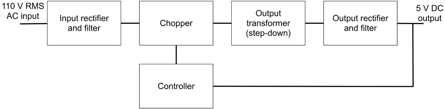
Figure 7-15. An SMPS
The high-voltage AC input is rectified and smoothed to produce high-voltage DC in the same way as Recipe 7.2 but without using a transformer first. This DC is then “chopped” or switched at high frequency (often around 60kHz) into a series of short pulses that then feed an output transformer that steps down the high-frequency AC. The resulting low-voltage AC is then rectified and filtered into low-voltage DC. Because the transformer operates at such a high frequency, it can be made much smaller and lighter than a 60Hz transformer.
Voltage regulation is achieved by feedback from the DC output to the controller that alters the width of the pulses being chopped that in turn alters the DC output voltage.
To keep the DC output isolated from the high-voltage AC, the feedback path to the controller uses an opto-isolator (Recipe 5.8).
This might seem like a lot of extra complexity, but the size, weight, and cost advantages of reducing the transformer size is enough to make SMPSs worthwhile.
Although there are ICs that do a lot of the work of an SMPS, they still require quite a few external components such as an opto-isolator and a high-frequency transformer.
Another advantage of SMPSs over transformer-based power supplies is that they can generally accept input voltages from 80–240V, and if the input voltage is higher, you just end up with shorter pulses to generate the same output voltage.
See Also
For the old-fashioned transformer-based approach to AC to low-voltage DC conversion, see Recipe 7.2.
For more information on transformers see Recipe 3.9 and for opto-isolators see Recipe 5.8.
7.12 Multiply Your Voltage
Solution
This is a job for the very elegant voltage-multiplier circuit, which uses a ladder of diodes and capacitors to increase the voltage without the use of inductors. It can be built in multiple stages to increase the voltage by different multiples. The schematic of Figure 7-16 shows a four-stage voltage multiplier that will multiply the AC voltage by 4.
Discussion
To understand how this circuit works, consider what happens at the peak positive and negative value of the AC inputs. When the input is at its negative maximum, C1 will be charged through D1. On the next positive maximum, C1 will still be charged to the peak, but now, the input will be effectively added to C1. If we stopped there this would be a voltage doubler, but now C2 will charge from the next negative peak and so on until the output is at four times the peak input voltage.
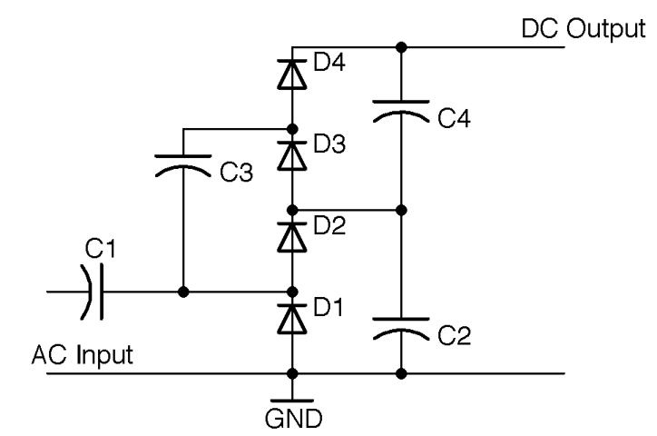
Figure 7-16. A Four-Stage Voltage Multiplier
The diodes should all be specified with a maximum voltage greater than the RMS AC input voltage times 1.4 (peak voltage). When selecting the capacitors (which should all be of the same value), you have a similar problem to that of selecting a smoothing capacitor in Recipe 7.2. If there is no load on the output then you can use very low value capacitors, but as soon as you add a load, they will discharge through it creating a ripple. Given that you will want the capacitors to be nonpolarized (no electrolytics here) and high-voltage, then you are likely to use something like 10nF capacitors rated for the same maximum voltage as the diodes for a low-current load such as a Geiger–Müller tube.
This kind of circuit is often used in high-voltage applications to multiply an initially high voltage up to even higher voltages.
See Also
For an example of using this kind of voltage multiplier in a power supply for a Geiger–Müller tube, see Recipe 7.14.
For background information on diodes and capacitors, see Recipe 4.1 and Recipe 3.1, respectively, and for background on AC see Recipe 1.7.
7.13 Supply High Voltage at 450V
Solution
Warning: High Voltage
This circuit can generate voltages approaching 1000V. Although this is at low current, it will still give you a nasty jolt and could have disastrous consequences if you have a pacemaker or heart problems, so please be careful if you decide to make this recipe.
This is especially true if you reuse the transformer from the flash unit of a disposable camera, as these units have a large capacitor charged to 400V or more that can really hurt. So discharge the capacitor first (Recipe 21.7).
Use a version of the inverter circuit of Recipe 7.10 to drive a small high-frequency transformer. Figure 7-17 shows the schematic for the power supply. Note that D1 and C4 should both be rated at 1000V.
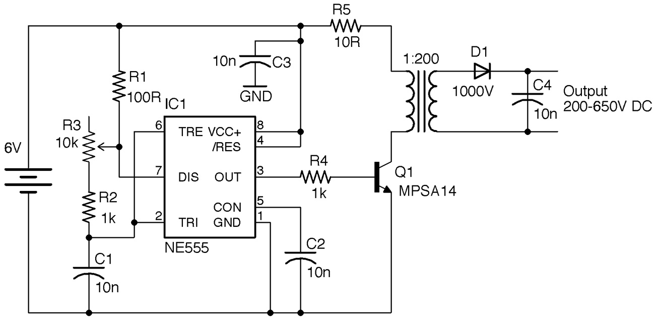
Figure 7-17. Schematic for High-Voltage DC Supply
The 555 timer is designed to provide a frequency of between 7kHz and 48kHz controlled using the variable resistor R3. The Darlington transistor provides pulsed current to the transformer, the output of which is rectified and smoothed.
Altering the frequency will alter the output voltage. With a high-voltage multimeter (1000V DC) adjust the variable resistor until the maximum voltage is found. For my transformer this took place at a frequency of 35kHz.
Discussion
Figure 7-18 shows the project built on two pieces of breadboard. The left breadboard has the 555 oscillator and the righthand board the transistor and high-voltage part of the design.
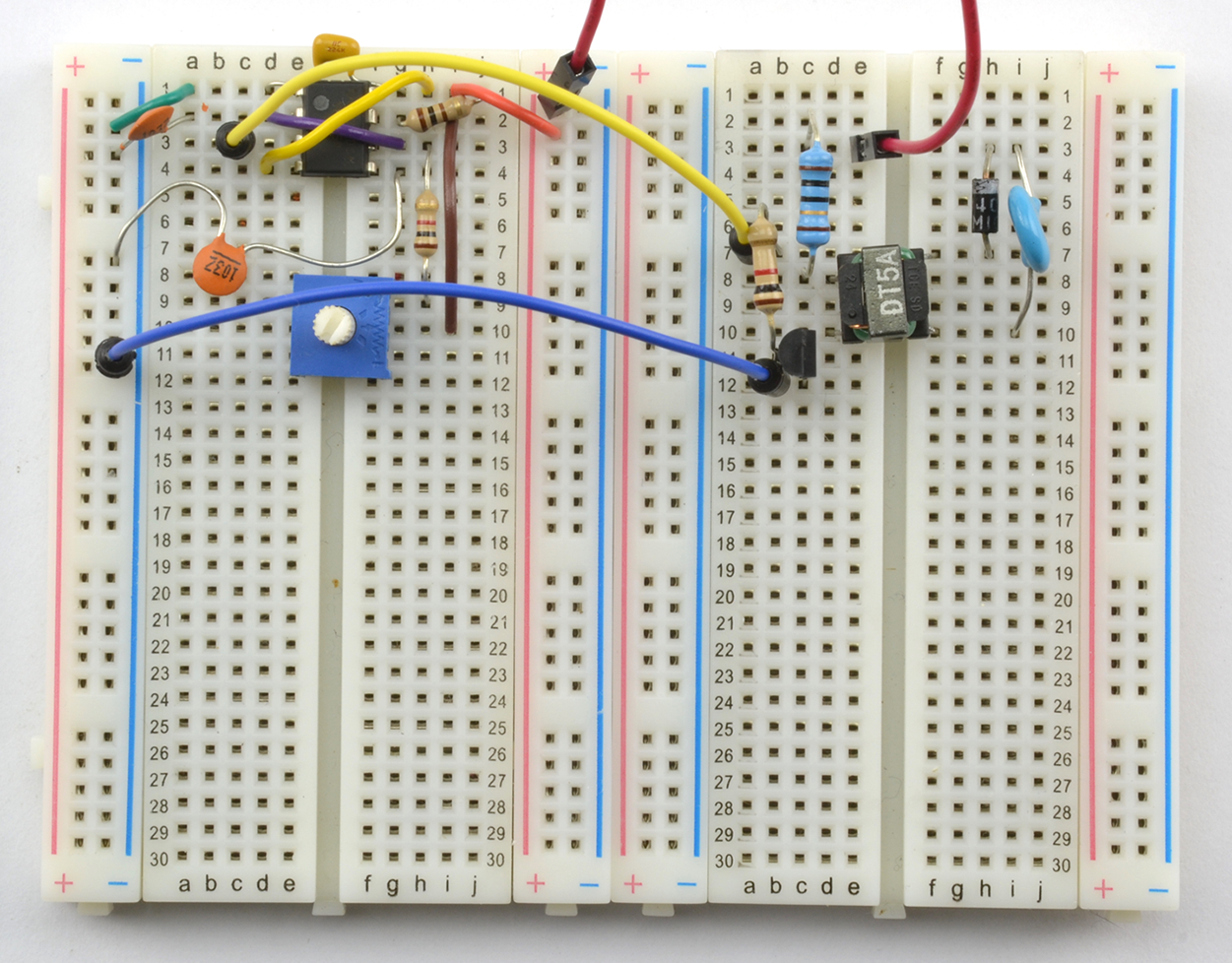
Figure 7-18. High-Voltage DC Supply on Breadboard
As you can see, the high-frequency transformer is tiny. The device I used is marked DT5A and is scavenged from the flash unit of an old disposable camera.
To check the output voltage, you will need a voltmeter with a 1000V DC range. Modern digital multimeters generally have an input impedance of around 10MΩ. At 1000V that means that a load current of 1kV / 10MΩ = 100nA. This does not sound like much, but for a low-current circuit like Figure 7-17, this loading may well reduce the voltage being measured. Increasing the value of C4, perhaps by putting a couple of capacitors of the same value in parallel with the original C4, should tell you if the multimeter is having an effect.
To measure high voltages reliably, you can use a specialist high-voltage meter with a very high input impedance, but these are expensive.
See Also
See Recipe 7.14 for a version of this design that adds a three-stage voltage multiplier to increase the output voltage.
For information on using the 555 timer, see Recipe 16.6.
For information on measuring high voltages, see Recipe 21.8.
To build circuits using a solderless breadboard, see Recipe 20.1.
7.14 Even Higher Voltage Supply (> 1kV)
Problem
The 450V output of Recipe 7.13 is not enough—you need 1.2–1.6kV for a Geiger–Müller tube that detects alpha radiation.
Solution
Add a three-stage voltage multiplier to the schematic of Recipe 7.13. The result of this is shown in Figure 7-19.
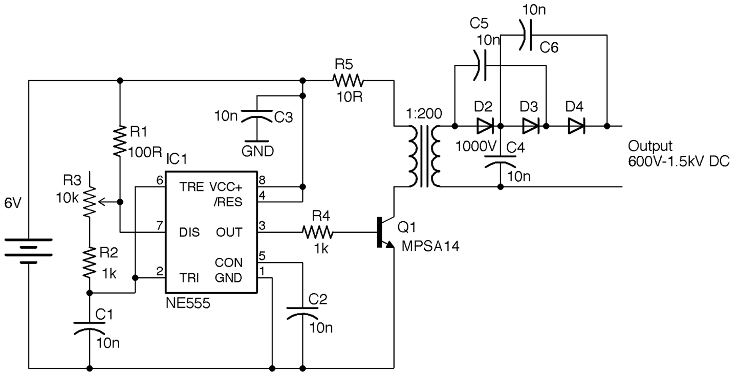
Figure 7-19. Adding a Voltage Trippler to the High-Voltage Supply
The diodes, C4, C5, and C6, can all still be rated at 1kV since the voltage across each should still be under 1kV.
Discussion
As with the design of Recipe 7.13 the output of this design is likely to contain a few volts of unwanted noise.
See Also
For a version of this design without the voltage multiplier, see Recipe 7.13.
7.15 Very Very High Voltage Supply (Solid-State Tesla Coil)
Solution
One common and safe design for a Tesla coil uses a homemade transformer. Figure 7-20 shows the completed Tesla coil illuminating an LED from a distance of half an inch and Figure 7-21 shows the power supply built on the breadboard.
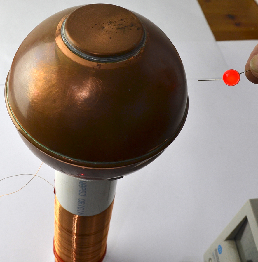
Figure 7-20. A Tesla Coil Lighting an LED
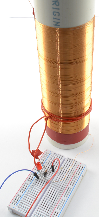
Figure 7-21. A Tesla Coil on Breadboard
Figure 7-22 shows the schematic for the project that uses a self-oscillating design based around a transformer and transistor.
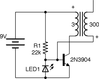
Figure 7-22. A Tesla Coil Schematic
The transformer for this design is made from a length of 2-inch plastic pipe onto which around 300 turns of 34 SWG (30 AWG) enameled copper wire are wound next to each other. The primary is made up of just three turns of plastic insulated multicore wire.
This circuit is called a solid-state flyback converter (sometimes called a slayer exciter). The top end of the transformer secondary is not directly connected to anything, but with the top end of the coil connected to something with a large area (such as the copper ball I used) there is a small stray capacitance to ground. The top surface of the large area could be a metal plate or various other arrangements, as long as it’s made from a large conducting area without too many sharp points to encourage discharge.
When power is first applied to the circuit, the transistor will turn on through R1, resulting in a large current flowing through the three turns of the transformer primary. This induces current to flow through the secondary, creating a potential difference due to the stray capacitance. Although small, this capacitance is sufficient to reduce the voltage on the bottom end of the secondary (and base of the transistor) to such an extent that the transistor turns off. The LED ensures that the base never falls more than 1.8V (the forward voltage of the LED) below ground. Because the transistor turns off, the magnetic field collapses and R1 reasserts its influence over the transistor’s base to turn the transistor back on and so the cycle continues.
If you get the connections of the primary the wrong way around, or even just the geometry of the secondary wrong, there is a chance the transformer will turn on but oscillation fail to start, which will rapidly destroy the transistor. If all is well, LED1 will light. A lab power supply with current limiting is very useful in this situation (see Recipe 21.1).
Discussion
Holding a second LED close to the high-voltage end of the secondary will cause it to light. By holding one lead of the LED, you will be providing a weak path to ground.
A quick way to increase the power of the circuit is to place several transistors in parallel (all three pins). By using four 2N3904s I was able to generate enough voltage to cause the gas in a compact florescent lamp to ionize, lighting the lamp from a range of almost a foot.
See Also
For information on prototyping with a solderless breadboard, see Recipe 20.1.
You can see this Tesla coil in action at https://youtu.be/-DEpQH7KMj4.
For other types of high-voltage power supply, see Recipe 7.13 and Recipe 7.14. The “joule thief” circuit (Recipe 8.7) operates in a similar way to this design.
To see a miniature Tesla coil design in action using a ferrite core rather than an open tube, visit https://www.youtube.com/watch?v=iMoDAspGPPc. The design here uses the same schematic as in Figure 7-22.
If you search the internet for Tesla coil, you will find some incredible builds.
7.16 Blow a Fuse
Solution
Use a fuse. Figure 7-23 shows a selection of fuses.
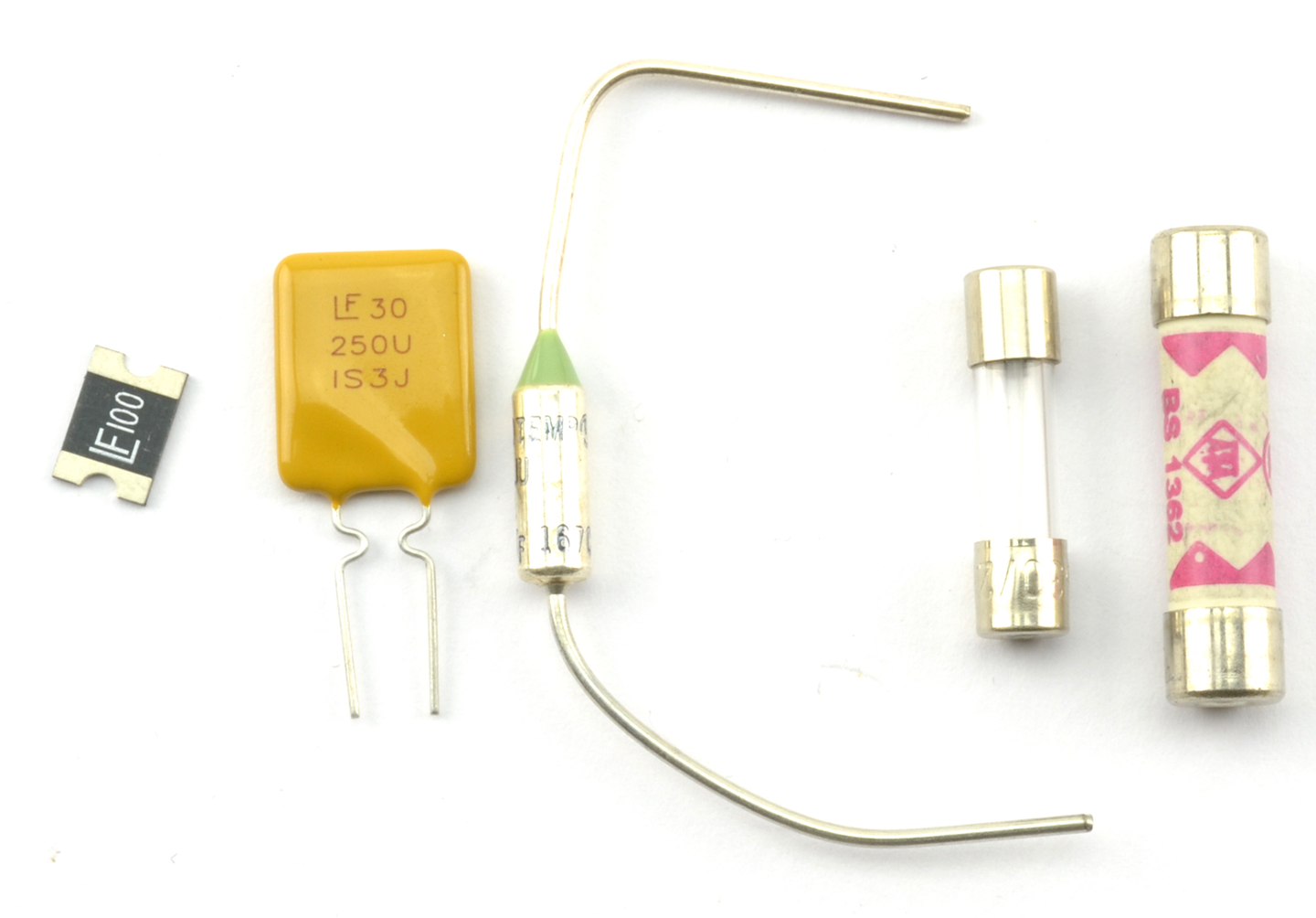
Figure 7-23. From Left to Right: SMD Polyfuse, Polyfuse, Thermal Fuse, 20mm Fuse, and 25mm Fuse
Fuses can be broadly classified as one-shot traditional fuses or polyfuses. As the name suggests, one-shot fuses can only be used once. When their current or temperature limits have been exceeded and they have blown, that’s it, they must be discarded. For this reason they are generally attached to electronics using a fuse holder, so they can be replaced easily.
Polyfuses (a.k.a. resettable fuses) do not blow, but when the current through them increases above their limit value, their resistance increases, only resetting when the current returns to zero and they have cooled down. This means they can be permanently attached to a circuit. You will often find them used in places like USB ports, where you need to protect computer ports against overcurrent by misbehaving peripherals. Polyfuses use the same technology as PTC thermistors (see Recipe 2.9).
Discussion
In modern circuit design, and especially for low-voltage and relatively low-current use, polyfuses are the best approach. However, for AC applications and other high-current situations, where overcurrent will only happen if something is seriously wrong, then traditional single-use fuses are the safest option because they require manual intervention before the power can be reapplied to the downstream circuit.
If a single-use fuse blows, then work out why it blew before replacing it. The most likely cause of overcurrent is a short circuit, either from wires touching that should not be touching, or a component failing that causes some part of the circuit to draw more current than it should.
There are a number of different single-use fuses:
- Slow-blow—survives short periods of overcurrent. For example, for use with a motor that draws a lot of current when starting.
- Fast-blow—blows as soon as the current is exceeded.
- Thermal—designed to blow on overcurrent, but also if the fuse gets hot because of external influences such as fire.
See Also
To test a fuse, see Recipe 21.5.
For a circuit to produce a constant current, see Recipe 7.7.
To protect a circuit against accidental polarity reversal, see Recipe 7.17.
7.17 Protect from Polarity Errors
Solution
Many ICs and circuits designed with discrete transistors will be destroyed by overcurrent and hence heating if the power is applied with the wrong polarity.
If you don’t care about a small voltage drop of 0.5V to 1V, then use a single diode from the positive battery terminal to the positive supply of your circuit (see Figure 7-24).
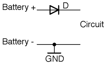
Figure 7-24. Protecting Against Reverse Polarity with a Diode
Remember to select a diode that can handle the current that you expect the circuit to draw.
If you can’t afford to lose a volt through the diode but are losing 0.2–0.3V, then use a Schottky diode in place of the regular diode.
If even 0.3V is too much to lose, then use an P-channel MOSFET as shown in the circuit in Figure 7-25.
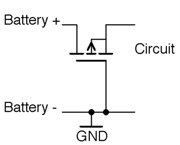
Figure 7-25. Reverse Polarity Protection Using a MOSFET
With the correct polarity, the P-channel MOSFET’s gate-drain voltage will be high enough to keep the MOSFET on. Since MOSFETs with extremely low on-resistances are available, there will be very little voltage drop across the MOSFET to the load. The circuit only works for battery-supply voltages over the gate-threshold voltage, or the MOSFET will not turn on.
When the polarity is reversed, the MOSFET will be firmly off, preventing any significant current from flowing into the load circuit.
Remember that the link between the gate and other connections of the MOSFET is capacitative and so no current can leak through the gate to the negative terminal of the battery.
Although almost by tradition people tend to prefer to switch and use polarity protection on the positive supply, you can also do the same trick with an N-channel MOSFET on the negative battery supply as shown in Figure 7-26.
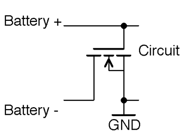
Figure 7-26. Negative Side Polarity Protection
Discussion
It’s a good idea to include polarity protection in any battery-powered project, even with a 9V battery that has a clip that only goes one way around, because it is all too easy to touch the wrong contacts together.
Using a MOSFET is probably the cheapest way to protect a design, as it can cope with several amps and will generally be smaller and cheaper than a diode with the same properties, especially in surface-mount technology.
See Also
To use fuses to protect a circuit against overcurrent, see Recipe 7.16.
For background on diodes, see Chapter 4.
For more information on MOSFETs, see Recipe 5.3.