Table of Contents for
Electronics Cookbook
 Electronics Cookbook
Published by
O'Reilly Media, Inc., 2017
Electronics Cookbook
Published by
O'Reilly Media, Inc., 2017
- Cover
- nav
- Electronics Cookbook
- Electronics Cookbook
- Preface
- Theory
- Resistors
- Capacitors and Inductors
- Diodes
- Transistors and Integrated Circuits
- Switches and Relays
- Power Supplies
- Batteries
- Solar Power
- Arduino and Raspberry Pi
- Switching
- Sensors
- Motors
- LEDs and Displays
- Digital ICs
- Analog
- Operational Amplifiers
- Audio
- Radio Frequency
- Construction
- Tools
- Parts and Suppliers
- Arduino Pinouts
- Raspberry Pi Pinouts
- Units and Prefixes
- Index
- About the Author
- Colophon
Chapter 10. Arduino and Raspberry Pi
10.0 Introduction
There is a good chance that any electronics project that you embark on will involve the use of a microcontroller (in the form of an Arduino) or a single-board computer (SBC) like the Raspberry Pi. Our gadgets are becoming more intelligent, requiring a little computer brain to control them; they are also becoming more connected, often needing an interface to the internet.
A typical Maker’s electronics project these days will involve the use of a microcontroller or SBC with some electronics to switch things or sense value, or both. These extra electronics are attached to the microcontroller or SBC using its GPIO (general-purpose input/output) pins.
In this chapter the recipes mostly focus on the electronic side of interfacing with a microcontroller or SBC in general, but will also use the Arduino and Raspberry Pi as examples.
10.1 Explore Arduino
Problem
You want to understand just what an “Arduino” is and why it finds its way into so many electronics projects.
Solution
Figure 10-1 shows the most popular flavor of Arduino, the Arduino Uno R3.
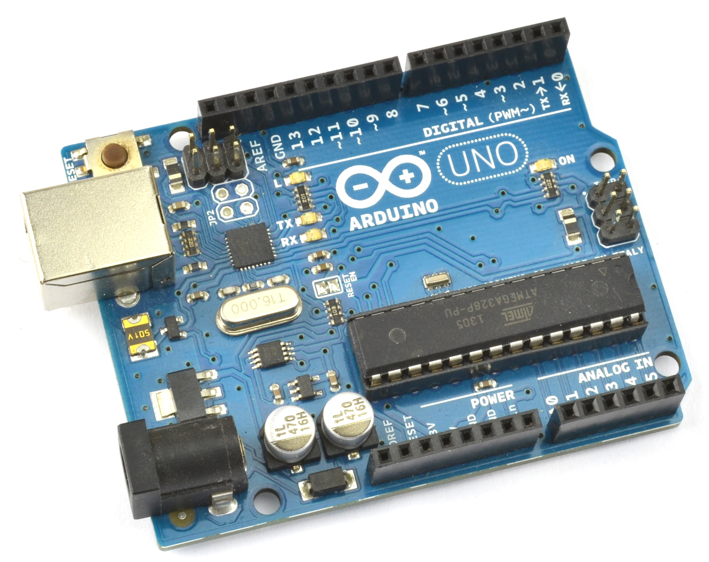
Figure 10-1. An Arduino Uno
An Arduino is not a microcontroller but instead a microcontroller interface board. It has a microcontroller chip on the board, but it also has a whole load of other components that provide:
- Regulated power to the microcontroller
- A USB interface to program the Arduino from your computer
- A “power” LED
- A “user” LED connected to one of its pins that can be turned on and off programatically
- A 16MHz quartz crystal, necessary for the microcontroller’s operation
- GPIO sockets for connecting external electronics
An Arduino does not do anything until it has been programmed. That is, you have to use your computer to write some instructions in the programming language C that can control and read the GPIO pins. Special software, called the Arduino IDE, is provided to both write the programs and then upload them onto the Arduino using a USB cable. Figure 10-2 shows the Arduino IDE with the “Blink” program loaded and ready to transfer to your Arduino. As its name suggests, the Blink program simply makes the Arduino’s built-in LED blink on and off and is the starting point for most people’s Arduino adventures.
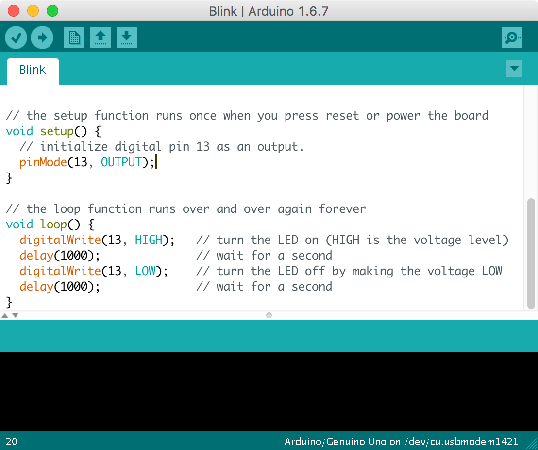
Figure 10-2. The Arduino IDE
You can download the Arduino IDE from http://arduino.cc.
In this book, it will be assumed that you have experimented with Arduino and at least got as far as uploading a program onto it to make an LED blink. If you are new to programming or need a slower-paced introduction to Arduino, then see some of the book suggestions at the end of this recipe.
Discussion
In addition to the GPIO pins that you will learn more about in Recipe 10.7 the Arduino also has peripheral interfaces for I2C (Recipe 14.9 and Recipe 14.10) and SPI devices (Recipe 19.4).
The Arduino is an extremely useful and reliable component to use in your designs, even if it is just while you are prototyping the project and will later build your own design with a microcontroller.
In addition to the Arduino Uno shown in Figure 10-1, there are many other types of Arduinos that are all programmed the same way. This means you can select an Arduino based on its price, size, and number of GPIO connections.
See Also
There are many excellent books written about Arduino that will help you fill in the background. Two I particularly recommend are:
- If you are new to programming: Programming Arduino: Getting Started with Sketches by Simon Monk, TAB DIY, 2016.
- For an encyclopedic Arduino reference: The Arduino Cookbook by Michael Margolis, O’Reilly, 2011.
The following is a list of some of the Arduino-related recipes in this book, outside of this chapter:
- Recipe 11.6
- Most of Chapter 12
- Most of Chapter 13
- Most of Chapter 14
- Recipe 18.1
- Recipe 19.3
- Recipe 19.4
10.2 Downloading and Using the Book’s Arduino Sketches
Solution
All the Arduino sketches and Python programs for Raspberry Pi for this book are downloadable from GitHub.
To use the Arduino sketches, download them from GitHub by cloning the directory if you are a git user, or use the Download Zip option behind the Clone or Download button on the GitHub page. You do not need to have a GitHub login to download the files.
Once extracted, the directory contains a directory called arduino with each of the Arduino sketches inside its own directory. Double-clicking on it will open the sketch in the Arduino IDE.
Discussion
An alternative way to access the sketches is to copy the contents of the arduino directory that you downloaded from GitHub into your Arduino IDE’s sketches directory, which is found in your operating system’s Documents or My Documents (Windows) folder in a directory called Arduino. Then you will be able to open any of the sketches from the File→Sketchbook menu of the Arduino IDE.
See Also
To download the Python files for Raspberry Pi, see Recipe 10.4.
If you are looking for a primer to teach you Arduino C, then my book Programming Arduino: Getting Started with Sketches (TAB DIY, 2016) should help you out.
10.3 Explore Raspberry Pi
Problem
You want to understand just what a “Raspberry Pi” is and why it finds its way into so many electronics projects.
Solution
A Raspberry Pi (Figure 10-3) is an SBC running a version of Debian Linux (called Raspbian) as an operating system. You can plug in a keyboard, mouse, and monitor and use it to browse the internet just like a “normal” computer.
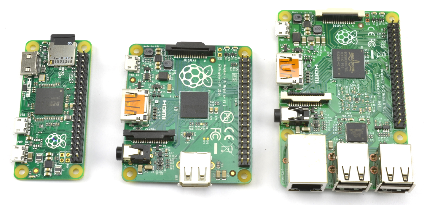
Figure 10-3. From Left to Right: Raspberry Pi Zero Model A and Pi 2 Model B
The Raspberry Pi is available in a number of different sizes, from the very low-cost Pi Zero up to the Model 3, which includes built-in WiFi.
The reason the Raspberry Pi has become popular for electronics projects is that, like the Arduino, it also has GPIO pins that you can connect to external electronics. What’s more, because the Raspberry Pi can be easily connected to the internet, you can also use it for all sorts of Internet of Things (IoT) projects.
When it comes to programming the Raspberry Pi, there are lots of options. In fact, all major programming languages are available to run on the Raspberry Pi, but the most popular language for electronics projects is probably Python, which is used in conjunction with the RPi.GPIO library.
While you need a computer to program an Arduino, to write programs for Raspberry Pi, you will use the Raspberry Pi itself.
Discussion
To use a Raspberry Pi unattended, you will want to be able to make your program automatically run when the Raspberry Pi Boots up (Recipe 10.3).
See Also
My book The Raspberry Pi Cookbook by O’Reilly (2016) is a cookbook like this, but dedicated entirely to the Raspberry Pi.
If you are new to programming and need a gentle introduction to Python programming on the Raspberry Pi, you might want to consider my book Programming the Raspberry Pi: Getting Started with Python (TAB DIY, 2015).
Here is a list of some of the Raspberry Pi-related recipes in this book outside of this chapter:
- Recipe 11.7
- Most of Chapter 12
- Most of Chapter 13
- Much of Chapter 14
- Recipe 18.2
- Recipe 19.2
10.4 Downloading and Running This Book’s Python Programs
Solution
All the Python programs for Raspberry Pi for this book can be found here: https://github.com/simonmonk/electronics_cookbook.
To use the programs, you can fetch them from GitHub directly onto your Raspberry Pi using the command:
$ git clone https://github.com/simonmonk/electronics_cookbook
This will also fetch all the Arduino sketches, but these can be ignored. You will find the Python programs in a directory called pi.
To run a program (e.g., blink.py) use the following command:
$ sudo python blink.py
Note that the sudo command is not required on the latest version of the Raspberry Pi’s operating system (Raspbian) so you may be able to just type:
$ python blink.py
Discussion
Although I suggested ignoring the Arduino sketches earlier in this recipe, in reality you can download and install the Arduino IDE onto a Raspberry Pi and then use the Raspberry Pi to program the Arduino (see http://spellfoundry.com/sleepy-pi/setting-arduino-ide-raspbian/).
See Also
To access the Arduino code, see Recipe 10.2.
To set a Raspberry Pi Python program to automatically run on startup, see Recipe 10.5.
If you are looking for a primer to teach you Python with Raspberry Pi, my book Programming Raspberry Pi: Getting Started with Python (TAB DIY, 2015) should help you out.
10.5 Run a Program on Your Raspberry Pi on Startup
Solution
Modify your rc.local file to run the program you want.
Edit the file /etc/rc.local by using the command:
$ sudo nano /etc/rc.local
Add the following line after the first block of comment lines that begin with #:
/usr/bin/python /home/pi/my_program.py &
It is important to include the & on the end of the command line so that it runs in the background; otherwise, your Raspberry Pi will not boot.
Discussion
Be careful when you edit rc.local, or you may stop your Raspberry Pi from booting.
See Also
For general background on Raspberry Pi, see Recipe 10.3.
10.6 Explore Alternatives to Arduino and Raspberry Pi
Solution
Table 10-1 lists some other popular boards (MC, microcontroller; SBC, single-board computer).
| Board | Type | Notes |
Arduino IDE Compatible |
Website |
|---|---|---|---|---|
| Digispark | MC | A tiny Arduino compatible with just a few GPIO pins that plugs straight into your computer’s USB port for programming. | Y | digistump.com |
| Adafruit Feather | MC | A small Arduino compatible with built-in LiPo battery charger and a range of wireless options. | Y | adafruit.com |
| NodeMCU | MC | A small, very low-cost board that can be easily converted to use the Arduino IDE. It has built-in WiFi. | Y | eBay |
| Particle Photon | MC | A small, low-cost Arduino compatible with built-in WiFi and IoT software built-in. | N | particle.io |
| Teensy3 | MC | A small, low-cost Arduino compatible. | Y | pjrc.com |
| BeagleBone Black | SBC | A Raspberry Pi alternative with more GPIO pins and analog inputs. | N/A | beagleboard.org |
| ODROID-XU4 | SBC | An 8-core 2GHZ South Korean monster SBC. | N/A | hardkernel.com |
Some of these boards are shown in Figure 10-4.
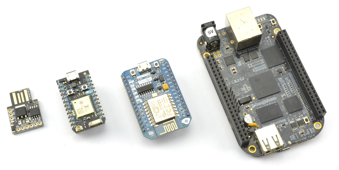
Figure 10-4. From Left to Right: Digispark, Photon, NodeMCU, and BeagleBone Black
Discussion
The Arduino IDE is a very flexible piece of software that can be easily extended to operate with unofficial Arduino-type boards. This means that you can stick to the Arduino IDE and the Arduino C programming language to program Arduino-like boards that may use a different processor or include useful addons such as WiFi, Bluetooth, or battery-charging hardware.
The Particle Photon deserves special mention, since although it uses a language that is based on Arduino C, you do not program it with the Arduino IDE, but rather with a web-based IDE. Deployment is then over the internet, allowing remote updating of applications. It also includes a very easy-to-use software framework for building IoT projects.
Other good boards to use where WiFi is required are any of the boards based on the ESP8266 modules, such as the NodeMCU and smaller modules like the ESP01. These can be programmed from the Arduino IDE. The ESP8266 boards are not as simple to use as the Photon but are extremely cheap.
See Also
For information on the Arduino see Recipe 10.1 and for the Raspberry Pi, see Recipe 10.3.
10.7 Switch Things On and Off
Solution
Microcontrollers and SBCs have GPIO pins that allow you to connect external electronics to them. Figure 10-5 shows the schematic for a typical GPIO pin within a microcontroller chip or SoC of a Raspberry Pi. The pin can function as either a digital input or digital output, under software control.
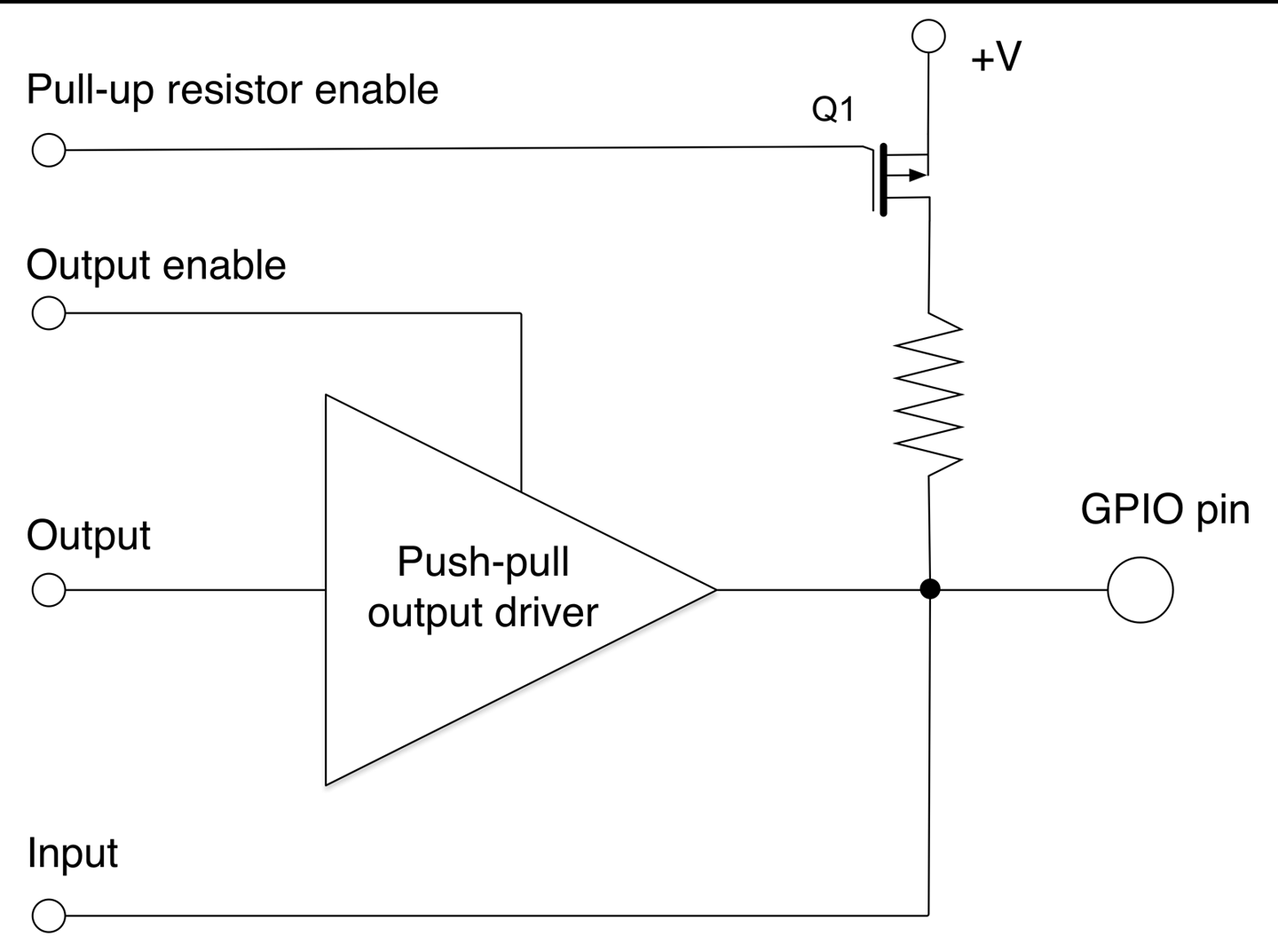
Figure 10-5. Schematic for a GPIO Pin
Referring to Figure 10-5, if the output enable control of the GPIO is set using software to be enabled, the pin functions as a digital output and the push-pull driver (Recipe 11.8) allows the GPIO pin to source or sink a few tens of milliamps.
If the push-pull driver is disabled, then the pin can function as a digital input. If the pull-up resistor enable control is set, then the transistor Q1 is enabled to allow the resistor to pull up the input to a default high. This is commonly used when connecting a switch to a digital input to prevent a floating input from oscillating between high and low (see Recipe 10.7).
Discussion
The GPIO schematic of Figure 10-5 is typical of most Arduino pins. Some of the Arduino pins (marked A0 to A5) can be used as analog inputs and for those pins, the GPIO is also connected to ADC hardware inside the microcontroller chip.
Some GPIO pins have pull-down resistors as well as pull-up resistors, which can be turned on and off in the same way as pull-down resistors.
Table 10-1 compares the GPIO features of an Arduino and Raspberry Pi 3.
| Feature | Arduino Uno R3 | Raspberry Pi 3 |
|---|---|---|
| Operating voltage | 5V | 3.3V |
| Maximum individual output current | 40mA | 18mA |
| Maximum total current for all pins used as outputs | 400mA | Not specified |
| Internal pull-up resistors | Y | Y |
| Internal pull-down resistors | N | Y |
| Number of GPIOs | 18 | 26 |
| Analog inputs | 6 | None |
Figures 10-6 and 10-7 describe each of the accessible GPIO and power pins available on an Arduino and Raspberry Pi 3, respectively.
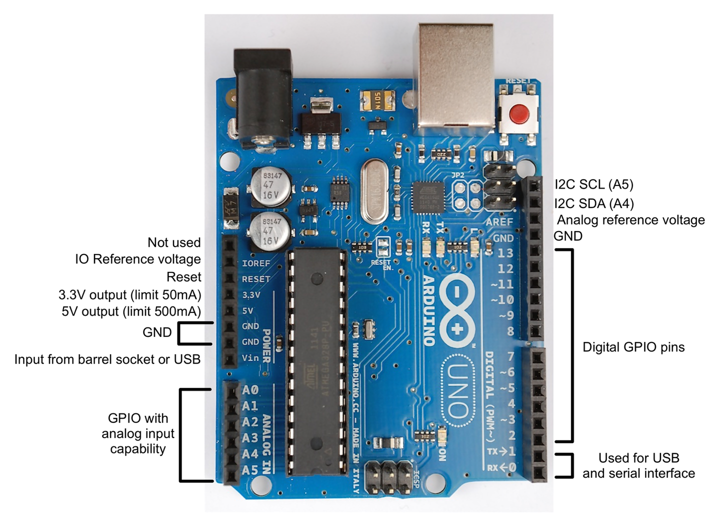
Figure 10-6. Arduino Uno R3 Pinout
Some of the pins require a little more explanation:
- IO reference voltage is the output voltage of the Arduino (5V for an Uno) but some other types of Arduinos operate at 3.3V. Intended for use by plug-in shields but rarely used.
- Vin is the supply voltage, which might be 9V if an external power supply is connected to the barrel jack, or 5V if the board is USB powered.
- The two I2Cs (IC to IC buses) are used for connecting to I2C devices (see Recipe 14.9), but are also connected to A4 and A5 of an Arduino Uno. On some other Arduino boards such as the Leonardo, these are separate.
- Analog reference voltage can be connected to a reference voltage below 5V to narrow the analog input range for greater precision at low voltages. If no connection is made, the analog inputs will be relative to 5V on an Arduino Uno.
- Pins 0 and 1 can in a pinch be used as extra GPIO pins, but if so you will need to disconnect anything attached to them to allow the USB connection to work. So generally it’s best not to use them.
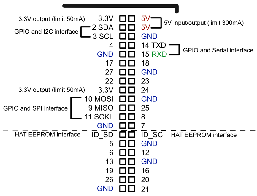
Figure 10-7. Raspberry Pi GPIO Connector Pinout
Unlike an Arduino, the GPIO pins on a Raspberry Pi are not labeled. If you are going to be connecting things to the GPIO pins, it’s a good idea to get a hold of a GPIO template, such as the Raspberry Leaf (Adafruit 2196), that fits over the GPIO pins allowing you to identify them easily.
Most of the pins on a Raspberry Pi can be used as GPIO, but some have second functions:
- Pins 2 and 3 can also be used to connect I2C devices.
- GPIO pins 9 to 11 can also be used as an SPI for devices that support that connection type.
- ID_SD and ID_SC are dedicated to an interface for any HAT (hardware attached to top) that fits over the GPIO connector and allows software to identify the HAT.
- Pins 14 and 15 can be used to provide TTL serial interfaces for devices such as GPS modules that often use that interface standard.
If you have an older Raspberry Pi (before the model B+) it will only have 26 pins on the GPIO connector. These are the same as the top 26 pins (above the dashed line) of the 40-pin layout of newer Raspberry Pis shown in Figure 10-7.
See Also
For an introduction to Arduino see Recipe 10.1 and for Raspberry Pi see Recipe 10.3.
Many of the recipes in Chapters 11, 12, 13, and 14 use GPIO pins.
10.8 Control Digital Outputs with Arduino
Solution
Use the pinMode function to set the pin to be an output and then use digitalWrite to turn the pin on and off. The following example program will make digital pin 13 (attached to the Arduino’s built-in LED) blink on and off:
constintledPin=13;voidsetup(){pinMode(ledPin,OUTPUT);}voidloop(){digitalWrite(ledPin,HIGH);// turn the LED ondelay(1000);// wait for a seconddigitalWrite(ledPin,LOW);// turn the LED offdelay(1000);// wait for a second}
The code for this sketch is available as part of the book downloads (Recipe 10.2). The sketch is called blink.
Discussion
The program (or “sketch” as they are known in the Arduino world) starts by defining a constant for the pin connected to the LED called ledPin, which is given the value 13. If you change your mind and decide to make another pin blink, you only need to change 13 to that pin number in one place in the code.
The setup function is run just once after the Arduino is reset. The pinMode function then specifies that ledPin is to be an OUTPUT. It is perfectly possible to change a pin’s mode while the sketch is running. You can find a good example of this with Charlieplexing (see Recipe 14.6).
The loop function will be run repeatedly over and over again, and each time it is run, it will first set ledPin (pin 13) high, wait a second (1000 milliseconds) then set it low, then wait another second, and so on.
See Also
For digital outputs on a Raspberry Pi, see Recipe 10.9 and for digital inputs on an Arduino see Recipe 10.10.
For the current-handling capabilities of an Arduino digital output, see Recipe 10.7.
10.9 Control Digital Outputs from Raspberry Pi
Solution
Use the RPi.GPIO library (included in Raspbian) with Python. The following example program will make GPIO pin 18 turn on and off once a second:
importRPi.GPIOasGPIOimporttimeGPIO.setmode(GPIO.BCM)led_pin=18GPIO.setup(led_pin,GPIO.OUT)try:whileTrue:GPIO.output(led_pin,True)# LED ontime.sleep(1)# delay 1 secondGPIO.output(led_pin,False)# LED offtime.sleep(1)# delay 1 secondfinally:("Cleaning up")GPIO.cleanup()
The code for this program is available as part of the book downloads (see Recipe 10.4). The file is called blink.py.
Unlike the Arduino, the Raspberry Pi does not have any user-controllable LEDs built in so to see this program in action see Recipe 14.1.
Discussion
The code starts by importing the GPIO and time libraries. It then sets the GPIO pin identification mode to be BCM (Broadcom). This is a hangover from the early days of Raspberry Pi when two ways of identifying the pins were almost equally used. However, for historical reasons, you still need to include this line at the top of all your Python programs. Some internet and book resources still exist that use the pin positions on the connector rather than the pins’ name. If you find such a resource, it will tell you to use a pin mode of BOARD instead of BCM.
The variable led_pin refers to the GPIO pin to be blinked and the pin set to be an output.
The main program loop is contained inside a try/finally block. This is not strictly speaking essential and the program will run just fine without it, but by calling GPIO.cleanup() whenever the program exits, all the GPIO pins are put back into a safe input state so that accidental shorts of the pins will not cause any damage.
Inside the while loop, the pin is first turned on, then there is a delay of a second, then it is turned off, etc. The sleep function takes a time in seconds as a parameter that can also be less than a second using a decimal notation. For example, to delay for half a second you would use time.sleep(0.5).
See Also
The Arduino equivalent to this program can be found in Recipe 10.8.
For digital inputs on a Raspberry Pi, see Recipe 10.11.
10.10 Connect Arduino to Digital Inputs Like Switches
Solution
Use the Arduino C digitalRead function. To see the result of the read, use the Arduino Serial Monitor. The following sketch illustrates this:
constintinputPin=7;voidsetup(){pinMode(inputPin,INPUT);Serial.begin(9600);}voidloop(){intreading=digitalRead(inputPin);Serial.println(reading);delay(500);}
You can find this sketch in the downloads for the book (see Recipe 10.2). It is called ch_10_digital_input.
The constant inputPin is defined as pin 7 and initialized to be an INPUT in the setup function.
The loop function first assigns the value resulting from carrying out a digitalRead on inputPin to the variable reading and then sends this value over the Arduino’s USB interface to the Serial Monitor. Finally, a delay of 500 milliseconds is added to slow things down to a manageable rate.
To open the Serial Monitor (Figure 10-8), click the rightmost icon on the Arduino IDE’s toolbar. This looks like a magnifying glass.
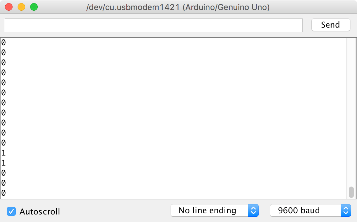
Figure 10-8. The Arduino Serial Monitor
You should see a steady stream of numbers appear as shown in Figure 10-8. These should be predominantly 0s, but there may be occasional 1s. Try attaching a male-to-male jumper wire or short length of solid core wire to pin 7 of the Arduino (Figure 10-9). You should find that you get a selection of 1s and 0s. This is because you are acting as an antenna and the digital input is picking up electromagnetic noise (most likely “hum”). The digital input is “floating” and since it has a very high input impedance, it is very sensitive to noise.
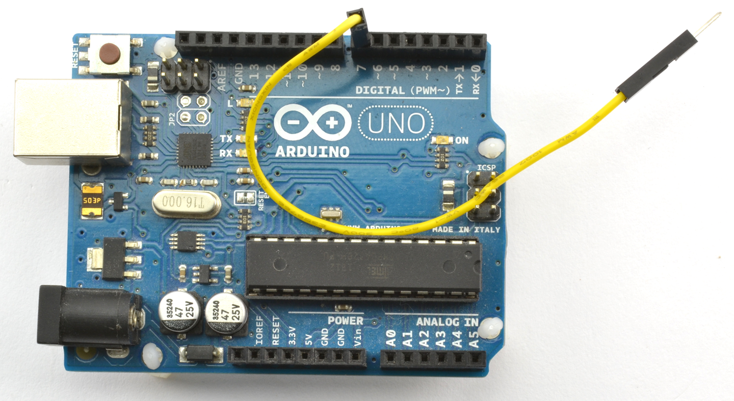
Figure 10-9. A Floating Digital Input
Next, try attaching the floating end of the lead to one of the GND connections on the Arduino as shown in Figure 10-10. You should see that the output in the Serial Monitor is all 0s.
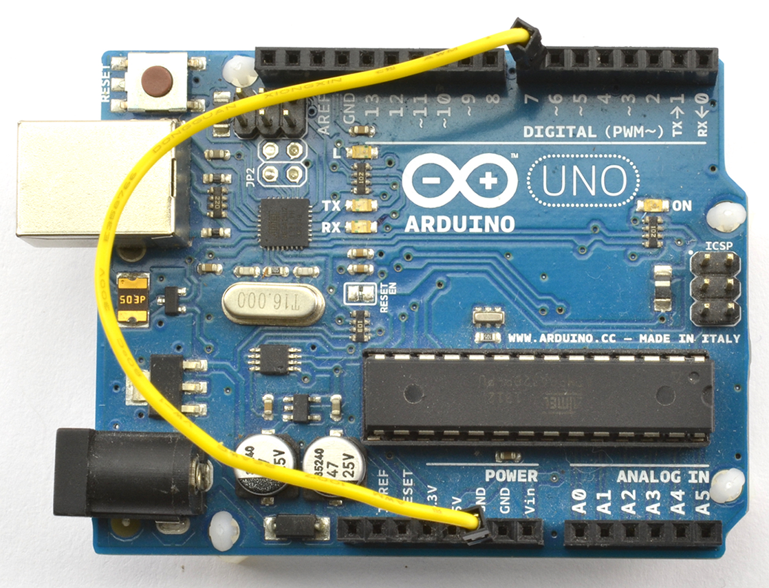
Figure 10-10. Connecting a Digital Input to GND
Finally, move the end of the wire that goes to GND to 5V and the Serial Monitor output should now be all 1s.
Discussion
The Arduino Serial Monitor is one of the few ways to see what is going on inside your Arduino and is often used to see what’s going wrong in a sketch.
See Also
For digital inputs on a Raspberry Pi, see Recipe 10.11.
10.11 Connect Raspberry Pi to Digital Inputs Like Switches
Solution
Use the RPi.GPIO library. The following example program reads GPIO23 every half second and prints out the result:
importRPi.GPIOasGPIOimporttimeGPIO.setmode(GPIO.BCM)input_pin=23GPIO.setup(input_pin,GPIO.IN)try:whileTrue:reading=GPIO.input(input_pin)(reading)time.sleep(0.5)finally:("Cleaning up")GPIO.cleanup()
The code for this program is available as part of the book downloads (see Recipe 10.4). The file is called ch_10_digital_input.py.
Discussion
When you run the preceding program, you will see mostly 0s in the terminal:
$ sudo python ch_10_digital_input.py
0
0
0
0
0
0
0
With both this program and Recipe 10.10 you can connect a switch to the digital input (Recipe 12.1) or use a female-to-female jumper wire to connect GPIO23 to either GND or 3.3V.
See Also
For digital inputs on the Arduino, see Recipe 10.10.
10.12 Read Analog Inputs on Arduino
Solution
Use the Arduino analogRead function and one of the Arduino pins A0 to A5 that can be used as analog inputs. The following example sketch writes the analog reading as a voltage to the Serial Monitor every half a second:
voidsetup(){pinMode(inputPin,INPUT);Serial.begin(9600);}constintinputPinA0;voidloop(){intreading=analogRead(inputPin);floatvolts=reading/204.6;Serial.println(volts);delay(500);}
You can find this sketch, which is called ch_10_analog_input, with the downloads (Recipe 10.2).
The sketch defines the inputPin as A0. When referring to one of the A0 to A5 pins on an Arduino, you have to use the letter and the number (A and 0), whereas for the other pins you just use the number.
The analogRead function returns a number between 0 and 1023, where 0 means 0V and 1023 means 5V. This number is converted to a voltage by dividing it by 204.6 (1023 / 5). Note that the analog range can be changed by connecting the Arduino AREF (analog reference) pin to a different voltage.
When you open the Serial Monitor you will see a series of values displayed. As with the digital inputs of Recipe 10.10 the analog input is floating and so the numbers (voltage on A0) will probably fluctuate something like this:
2.42
2.36
2.27
2.13
1.99
1.86
1.74
1.62
1.40
0.70
Discussion
Try the experiments in Recipe 10.11 and put a wire into A0. Touching the end of the wire with your fingers so that you act as a radio antenna should make the analog readings even more wild. Connecting A0 to the 5V connector of the Arduino should display a voltage reading of 5.00 on the Serial Monitor and GND will give you 0.00; connecting A0 to the 3.3V socket on the Arduino should give you a reading of around 3.30.
If the maximum voltage you want to measure is below 5V, then you can use the Arduino AREF pin to keep the 0–1023 range of readings but for a smaller voltage range and thus achieve higher precision.
For example, if you tie the AREF pin to the 3.3V pin on the Arduino you will get a full range of readings over the 3.3V range. The voltage at AREF needs to be stable and regulated or your readings will be inaccurate.
See Also
The Raspberry Pi does not have analog inputs, but you can use an ADC IC (Recipe 12.4).
10.13 Generate Analog Output on Arduino
Solution
Use the analogWrite function of the Arduino on one of the PWM-capable pins.
The following example sketch will set the brightness of an LED wired to pin 11. The brightness is set by sending a number between 0 and 255 from the Arduino Serial Monitor to the Arduino board. For the curious, 255 is 1 less than 2 to the power of 8.
constintoutputPin=11;voidsetup(){pinMode(outputPin,OUTPUT);Serial.begin(9600);Serial.println("Enter brightness 0 to 255");}voidloop(){if(Serial.available()){intbrightness=Serial.parseInt();if(brightness>=0&&brightness<=255){analogWrite(outputPin,brightness);Serial.println("Changed.");}else{Serial.println("0 to 255");}}}
You can find this sketch, which is called ch_10_analog_output, with the downloads for the book (Recipe 10.2).
In addition to illustrating PWM output from a GPIO pin, this example sketch also illustrates how you can send data from your computer to the Arduino via the Serial Monitor.
The setup function sets outputPin to be an OUTPUT and then starts serial communication. Finally, the setup function sends a message to the Serial Monitor instructing you how to use the sketch by sending a number between 0 and 255.
Inside the loop function, the call to Serial.available() tests to see if anything has been sent from the Serial Monitor, and if it has, it is converted into an int and assigned to the variable brightness. The analogWrite command is then used to set the output of outputPin.
To see this sketch in operation, you will first need to follow Recipe 14.1 and attach an LED to pin 11.
Open the Arduino IDE’s Serial Monitor (see Recipe 10.10) and then try some different values between 0 and 255 to see how the brightness changes (Figure 10-11).
Not Working?
If, when you type a value into the Serial Monitor and click Send, the LED changes brightness momentarily, but then turns off, the Line ending drop-down list at the bottom of the Serial Monitor (see Figure 10-11) is probably not set to “No line ending.”
What is happening is that the number is being sent and works, but then the line ending arrives as another message and is interpreted as being 0, turning the LED off again.
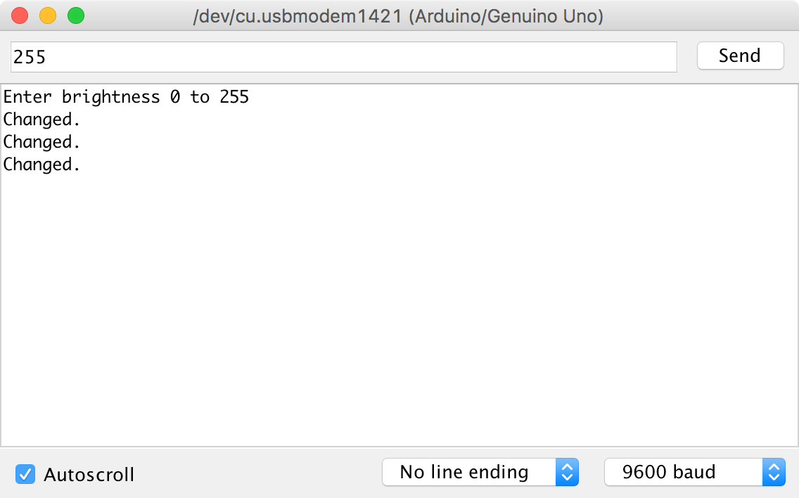
Figure 10-11. Setting the PWM Output from the Serial Monitor
Discussion
Not all the pins on an Arduino can be used for PWM like this. In fact, only the pins on the Arduino Uno marker with a ~ can. On an Arduino Uno, that’s pins 3, 5, 6, 9, 10, and 11. Other Arduino models have different sets of pins that are PWM-capable, but you will need to refer to the Arduino documentation to know which ones.
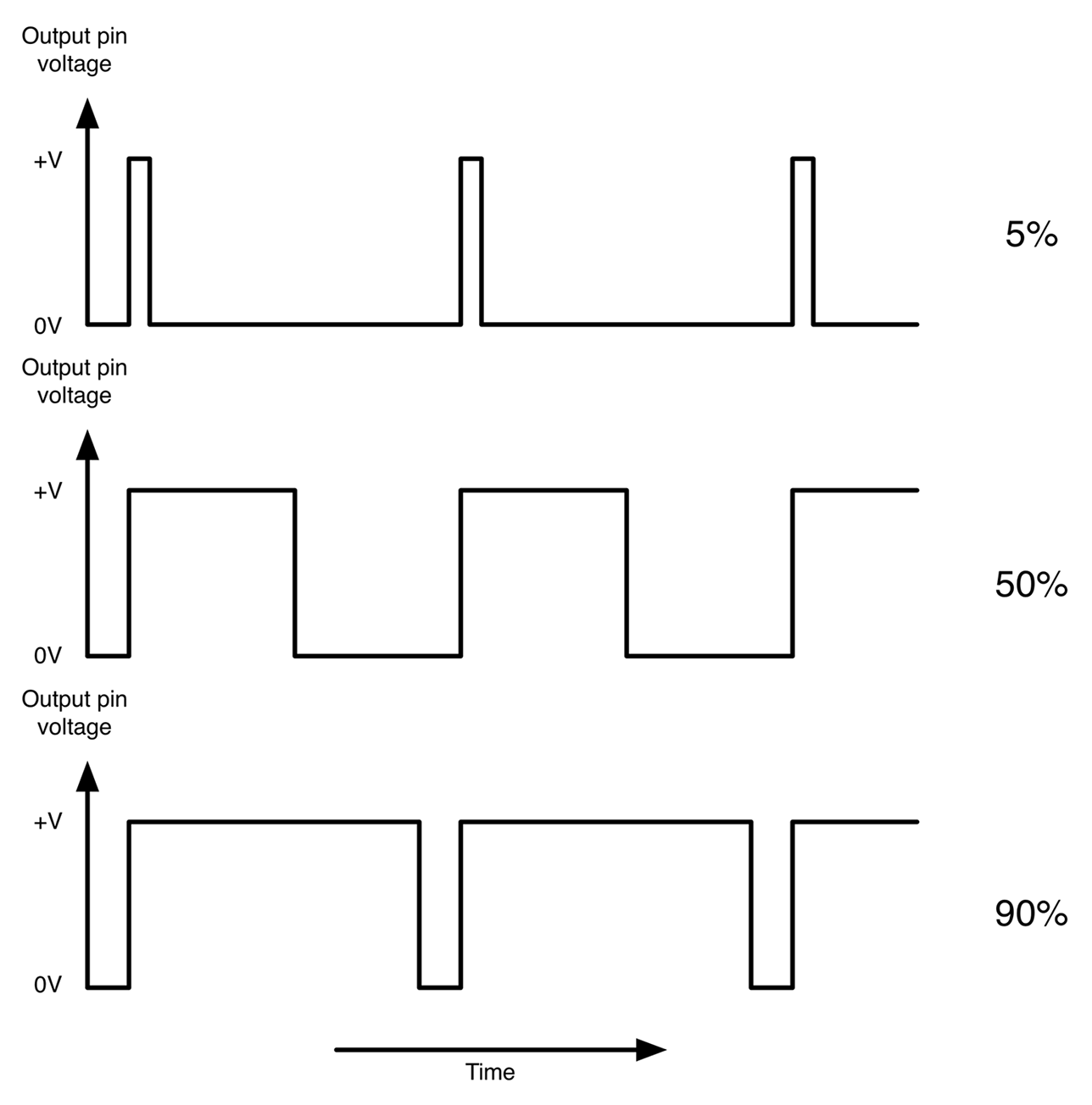
Figure 10-12. Pulse-Width Modulation
See Also
For the Raspberry Pi version of this recipe, see Recipe 10.14.
10.14 Generate Analog Output on Raspberry Pi
Solution
Use the PWM feature of the RPi.GPIO library to control the output power of a GPIO pin. The following Python example program illustrates this:
importRPi.GPIOasGPIOled_pin=18GPIO.setmode(GPIO.BCM)GPIO.setup(led_pin,GPIO.OUT)pwm_led=GPIO.PWM(led_pin,500)pwm_led.start(100)try:whileTrue:duty_s=raw_input("Enter Brightness (0 to 100):")duty=int(duty_s)pwm_led.ChangeDutyCycle(duty)finally:("Cleaning up")GPIO.cleanup()
You can find this program in the downloads for the book (see Recipe 10.4). If you are using Python 3 rather than Python 2, change the command raw_input to just input.
To see this program in action, you will need to attach an LED to GPIO pin 18 (see Recipe 14.1).
The RPi.GPIO library is a little more complex to use than its Arduino counterpart. After defining the pin as an output, you then have to create a PWM channel using the line:
pwm_led = GPIO.PWM(led_pin, 500)
The number 500 is the frequency of the PWM pulses in Hz. This PWM channel is then started using the following line:
pwm_led.start(100)
Here, the value of 100 is the initial duty cycle (percentage of time the pin is high) of the PWM signal (in this case, 100% of the time).
The rest of the script interacts with the user requesting a value of the duty cycle between 0 and 100. Run the program and try different versions of brightness as shown here:
$ sudo python led_brightness.py
Enter Brightness (0 to 100):0
Enter Brightness (0 to 100):20
Enter Brightness (0 to 100):10
Enter Brightness (0 to 100):5
Enter Brightness (0 to 100):1
Enter Brightness (0 to 100):90
When you want to exit the program, press CTRL-C.
Discussion
The Raspberry Pi does not use a real-time operating system. That is, at any one time, there are many differnt processes running. So if you are trying to generate pulses of an exact length such as with PWM, you will find that you get a certain amount of jitter in the LED brightness as the pulse generation is interrupted.
See Also
For the Arduino counterpart to this recipe, see Recipe 10.13.
10.15 Connect Raspberry Pi to I2C Devices
Problem
You want to enable the I2C bus on your Raspberry Pi to connect I2C peripherals to it such as the displays used in Recipe 14.9 and Recipe 14.10.
Solution
In the latest versions of Raspbian, enabling I2C (and for that matter SPI—Recipe 10.16) is simply a matter of using the Raspberry Pi configuration tool that you will find on the main menu under Preferences (Figure 10-13). Just check the box for I2C and click OK. You will be prompted to restart.
On older versions of Raspbian, the raspi-config tool does the same job.
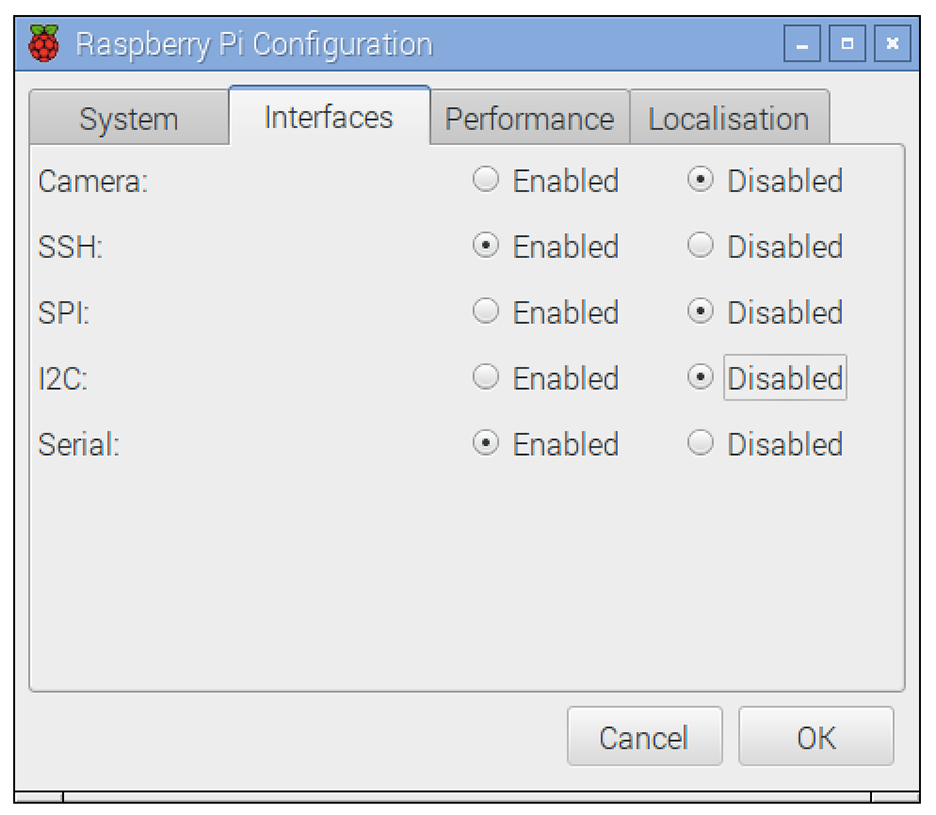
Figure 10-13. Pi Configuration Before Enabling I2C Using the Pi Configuration Tool
Start raspi-config using the following command:
$ sudo raspi-config
Then select Advanced from the menu and scroll down to I2C (Figure 10-14).
When you are asked “Would you like the ARM I2C interface to be enabled?” say “Yes.” You will also be asked if you want the I2C module to load at startup, to which you should also say “Yes.”
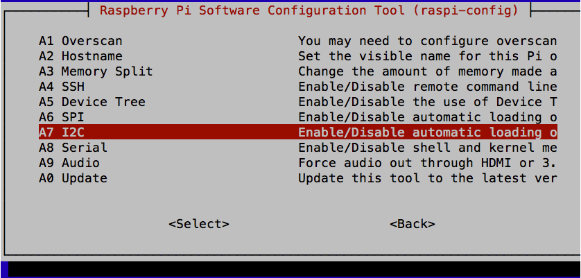
Figure 10-14. Enabling I2C Using raspi-config
Discussion
I2C is a commonly used standard for connecting devices together. It uses two data pins SDA (data) and SCL (clock) to transfer data bidirectionally between devices. Usually one of the devices on the bus is a microcontroller or in this case, the SoC of the Raspberry Pi. Multiple devices can be connected to the same I2C bus pins, so, for example, you could have both a display and a sensor connected to the same two bus pins, each device having its own unique address.
To use I2C devices from Python, install the Python I2C library by using the commands:
$ sudo apt-get update
$ sudo apt-get install python-smbus
You will then need to reboot the Raspberry Pi for the changes to take effect.
When using I2C hardware the i2c-tools software can be a great help in debugging and making sure devices are properly connected to the Raspberry Pi. This can be installed using the command:
$ sudo apt-get install i2c-tools
When you have a device attached to the I2C bus, running the i2cdetect utility will tell you if it’s connected and what I2C address it’s using, as shown in Figure 10-15.
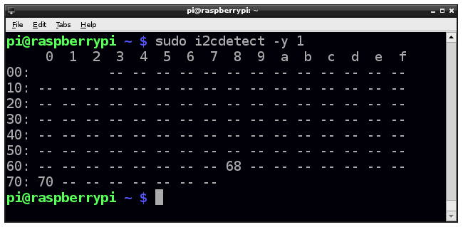
Figure 10-15. Using i2cdetect
See Also
To set up the Raspberry Pi’s SPI, see Recipe 10.16.
For recipes that connect I2C peripherals to a Raspberry Pi, see Recipe 14.9, Recipe 14.10, and Recipe 19.3.
10.16 Connect Raspberry Pi to SPI Devices
Solution
By default, Raspbian is not configured for the Raspberry Pi’s SPI. To enable it use the Raspberry Pi configuration tool found in the main menu under Preferences (as in Recipe 10.15), or on older versions of Raspbian, use raspi-config using the command:
$ sudo raspi-config
Then select Advanced, followed by SPI, and then “Yes” before rebooting your Raspberry Pi. After the reboot, SPI will be available.
Discussion
The SPI allows serial transfer of data between the Raspberry Pi and peripheral devices, such as ADCs and port expander chips, among other devices. It is similar in concept to I2C but uses four pins instead of two. As with I2C SPI data is synchronized with a clock signal (SCLK) but separate lines are used for each direction of communication: MOSI (master out slave in) and MISO (master in slave out) and a separate “Enable” pin is needed from the master for each of the devices connected to the bus. It is an older and less elegant standard than I2C but still widely used.
You may come across examples of interfacing with SPI that use an approach called bit banging, where the RPi.GPIO library is used to interface with the four GPIO pins used by the SPI.
See Also
Recipe 12.4 uses an SPI ADC converter chip.
The SPI is used in Recipe 12.4 and Recipe 19.4.
10.17 Level Conversion
Solution
When you are connecting a 3.3V-level output to a 5V input, with very few exceptions (see discussion), no level conversion is needed—you can connect the two directly.
However, if you want to connect a 5V output to a 3.3V input, then that’s a different matter. Direct connection will wall damage the 3.3V device. If the 3.3V device is specified as having 5V-tolerant inputs, then you can just connect the two together directly. Note that the inputs of a Raspberry Pi are not 5V tolerant, so you should connect them together using a voltage divider as shown in Figure 10-16.
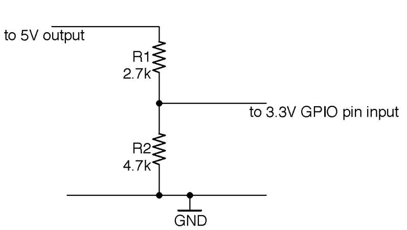
Figure 10-16. Reducing a 5V Signal to 3V
Discussion
Occasionally you will find a 5V device that specifies that the logic level for an input should be above 3.3V. For example, WS2812 LED ICs (Recipe 14.8) theoretically need an input greater than 4V to be considered as logic high according to their datasheet. In practice, I have always found them to work without level conversion, but if you are designing a product to sell, then you would not take that chance and the kind of level shifter shown in Figure 10-17 should be used.
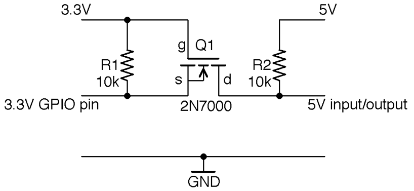
Figure 10-17. Bidirectional Level Shifting with a MOSFET
This circuit will actually convert levels in both directions; that is, 5V outputs will be reduced to 3.3V and 3.3V outputs increased to 5V. It makes use of the fact that MOSFETs have a “substrate” protection diode that prevents current from flowing from drain to source.
To understand how this circuit works, first consider the case where the 3.3V side is an output and the 5V side an input; that is, the level is being shifted up.
In this case, if the 3.3V GPIO is high, then the gate-source voltage will be 0V, the MOSFET will be off, and R2 will pull-up the 5V input HIGH. If the 3.3V GPIO output is low, the gate-source voltage will be 3.3V, the MOSFET will turn on, and the 5V input will be effectively connected to the LOW signal from the 3.3V side.
If we swap the direction so that the 5V side is now the output and the 3.3V side the input, then when the 5V output is HIGH the MOSFET source and gate will be at 3.3V, the MOSFET will be off, and the 3.3V input pulled up to 3.3V by R1. If the 5V output is LOW the MOSFET’s built-in protection diode will conduct, pulling the 3.3V input down to the diode’s forward voltage (about 0.6V). This turns the MOSFET on, pulling the 3.3V input fully to ground.
See Also
The simplest level conversion using just two resistors is a voltage divider as described in Recipe 2.6.
For a general background on MOSFETs see Recipe 5.3.
For an interesting discussion of the necessity of level shifting for Raspberry Pi inputs, see http://tansi.info/rp/interfacing5v.html.
If you have a lot of signals all requiring level shifting, then it makes sense to use a level-shifting IC or module such as these products from Adafruit: http://bit.ly/2lLHmuG (four signals) and http://bit.ly/2msMgku (eight signals).