Table of Contents for
Electronics Cookbook
 Electronics Cookbook
Published by
O'Reilly Media, Inc., 2017
Electronics Cookbook
Published by
O'Reilly Media, Inc., 2017
- Cover
- nav
- Electronics Cookbook
- Electronics Cookbook
- Preface
- Theory
- Resistors
- Capacitors and Inductors
- Diodes
- Transistors and Integrated Circuits
- Switches and Relays
- Power Supplies
- Batteries
- Solar Power
- Arduino and Raspberry Pi
- Switching
- Sensors
- Motors
- LEDs and Displays
- Digital ICs
- Analog
- Operational Amplifiers
- Audio
- Radio Frequency
- Construction
- Tools
- Parts and Suppliers
- Arduino Pinouts
- Raspberry Pi Pinouts
- Units and Prefixes
- Index
- About the Author
- Colophon
Chapter 19. Radio Frequency
19.0 Introduction
It used to be that any electronics book worth its salt would include discrete circuits for AM and FM broadcast receivers and maybe even discuss how an analog TV works. In these digital days, topics like this are only for historical interest.
For this reason, this chapter mostly concentrates on the use of digital communications using radio frequencies. The discussion of the nature of radio is restricted to this introduction. The recipes themselves are fundamentally practical.
We take radio frequency for granted now, but when it first became popular, it must have seemed like magic. After all, it allowed you to talk to someone miles away without any wires connecting them. How could this be possible?
Transmitters and the Law
Recipe 19.1, Recipe 19.2, and Recipe 19.4 are radio transmitters. Although most countries allow the use of low-power, short-range FM transmitters and allocate certain bands for use with packet radio, you should check your local regulations and make sure you are not breaking the law by using any of these designs.
Amplitude Modulation (AM)
It all starts with AM transmissions, which use a carrier frequency modulated by the audio signal that is being transmitted. Figure 19-1 shows how this works.
In Figure 19-1 the carrier frequency is only about 4.5 times the audio signal. In a real AM broadcast, the audio signal will generally be a maximum of 16kHz against a carrier frequency of 500kHz, making at least ten times as many cycles of carrier in each cycle of the audio frequency shown in Figure 19-1. But it’s easier to see what is going on with fewer cycles.
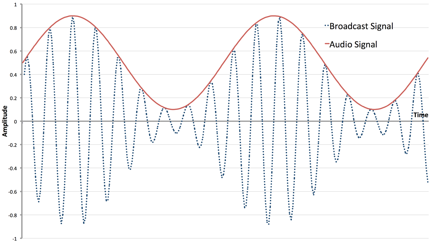
Figure 19-1. AM Transmission
Each transmitting station has its own frequency, and for AM public broadcasts in the medium wave (MW) band, this range is around 520kHz to 1600kHz. The amplitude of the carrier is modulated by the audio signal and the resulting signal broadcast through an antenna.
One of the reasons the quality of AM is so bad is that there are many other factors that can affect the amplitude of the carrier, including atmospheric conditions or changes in position of the receiver if you are listening in a moving vehicle.
When it comes to the receiver, you need to be able to separate the radio-frequency carrier (RF) from the audio signal.
The first step in this is to “tune in” to the transmission frequency you are interested in. This means using a narrow band-pass filter (Recipe 17.9) so that all the other stations get tuned out. This is traditionally accomplished by using a tuned circuit in the form of a fixed inductor (also acting as the antenna) and a variable capacitor that is varied to tune into different frequencies.
Since your ears cannot hear frequencies above 20kHz (lower as you get older) a radio carrier frequency of 500kHz or more will be inaudible. With your ears acting as a low-pass filter, you might expect that with suitable amplification of the tuned radio signal, you would be able to hear the audio signal modulating it. This is almost correct, but because the “average” of each cycle (whatever the amplitude) is zero (each positive wave followed by a negative one), you won’t hear anything. However, if you introduce a diode to remove one half of the signal (Figure 19-2), then suddenly the original audio signal can be separated and you will be able to hear the audio in the envelope of the AM signal and your ears will now happily be a low-pass filter for you.
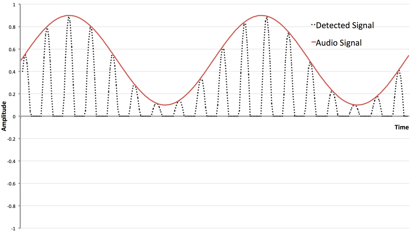
Figure 19-2. Detecting the Audio Signal from AM
The big empty space on the bottom of Figure 19-2 serves to show where the diode has removed the negative part of the tuned signal.
The earliest AM receivers (crystal sets) were literally a coil, antenna, variable capacitor, diode (germanium for its lower forward voltage), and sensitive headphones as shown in Figure 19-3.
Improvements have been made to the design of AM receivers, in particular amplification of the RF signal before detection, followed by further amplification to drive a loudspeaker, but the basic principles of an AM receiver are as they were a century ago.
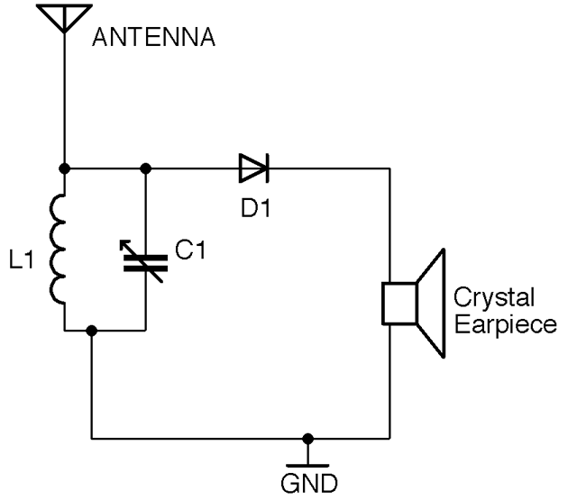
Figure 19-3. A Basic AM Receiver
Frequency Modulation (FM)
Frequency modulation (FM) improves on AM by varying the frequency of the carrier rather than its amplitude. This improves the quality of the sound being broadcast, as the frequency is immune from changes due to atmospheric conditions or movement of the receiver. Figure 19-4 shows how an audio signal would be used to modulate a carrier.
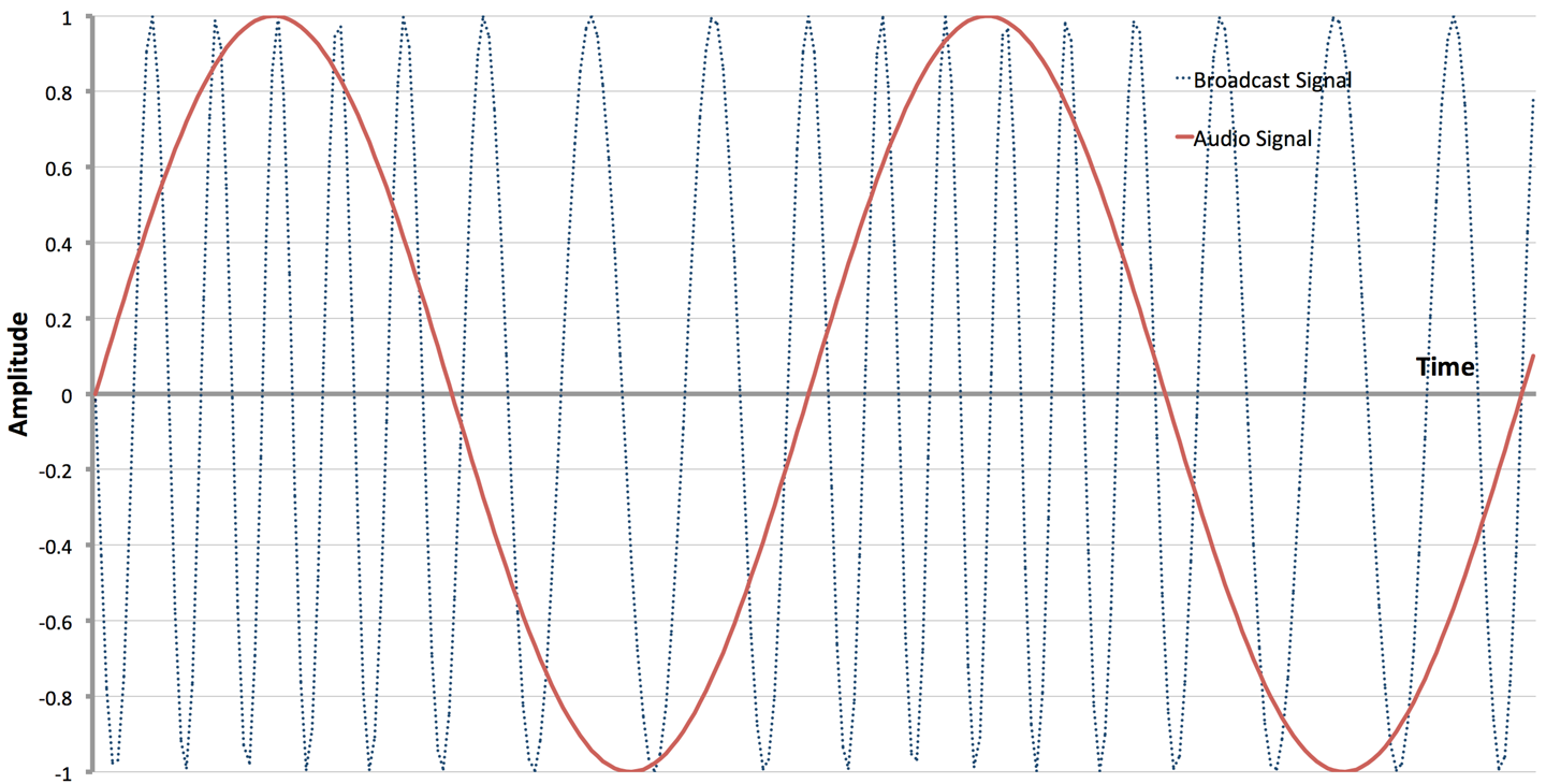
Figure 19-4. Frequency Modulation
To create an FM transmitter, a VCO (Recipe 16.10) is used. The audio signal is fed into the frequency control input of the VCO to vary the frequency. The first recipe in this chapter (Recipe 19.1) is a simple, low-power FM transmitter.
Extracting the audio signal from an FM broadcast can be accomplished by using a number of techniques, but perhaps the most common is to use a VCO in an arrangement called a phase-locked-loop (PLL). Figure 19-5 shows a PLL configured as an FM demodulator.
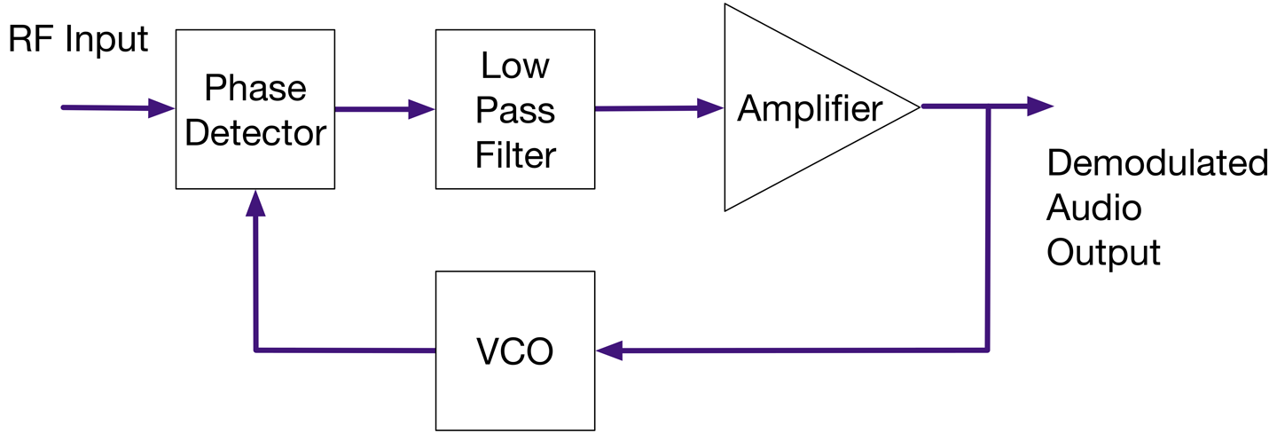
Figure 19-5. A Phase-Locked Loop FM Demodulator
The RF signal is first tuned to a particular frequency as with an AM receiver, but then to demodulate the original audio, the RF signal is fed into a phase comparator. The phase comparator produces an output that is zero if its two input signals are completely in phase. If the signals are out of phase with each other then the comparator produces an output proportional to the difference in phase. This signal is then low-pass filtered, amplified, and used to control a VCO whose output supplies the second input to the phase comparator. This feedback results in the VCO producing a signal of the same frequency as the RF input to the phase comparator. As the output of the VCO tracks the RF frequencies the small shifts in phase resulting from the modulation will result in the audio signal being available in the filtered and amplified output of the phase detector. The amplified output contains the demodulated audio signal almost as a side effect of the PLL tracking the broadcast signal.
PLL chips are available that include the VCO, phase comparator, and other parts all in one convenient package. However, if you are making an FM receiver, then you would just use an FM receiver IC that includes the RF amplification, PLL, and pretty much everything needed for the receiver aside from a few resistors, capacitors, and inductors.
Digital Radio
Radio is now very much a digital affair. FM radio receivers and transmitters are now often implemented as software-defined radios (SDRs). Processors are now so fast that with a very small amount of hardware they can produce and decode analog broadcast signals in software. For example, the filtering, phase detecting, etc. of a PLL can all be done as software algorithms rather than directly in hardware. In Recipe 19.2 you will find a recipe for a SDR FM transmitter using a Raspberry Pi.
In addition to using digital electronics to decode analog signals, the use of digital signals carried on RF is everywhere from your cellphone to the remote you use to unlock your car.
This chapter has several recipes for passing digital data wirelessly between devices.
19.1 Make an FM Radio Transmitter
Solution
Use a high-frequency VCO chip (MAX2606) set to operate in a frequency on the FM band and use the audio signal to make small adjustments to the frequency.
The schematic for this is shown in Figure 19-6.
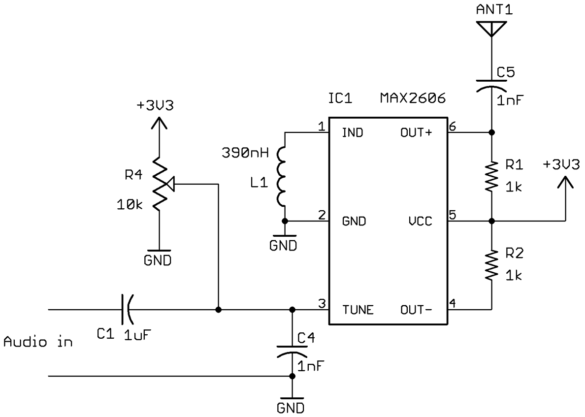
Figure 19-6. An FM Transmitter Using a VCO IC
The variable resistor R4 is used to tune the transmitter to a particular frequency. The antenna can be a telescopic FM antenna or simply a few feet of wire.
Discussion
The inductor L1 sets the center frequency of the VCO. The datasheet for this device indicates that an inductor of 390nH will give a center frequency of around 102MHz.
The control signal applied to the TUNE pin of the VCO comprises a fixed DC offset supplied by R4 (to allow tuning to a particular transmission frequency) and an audio signal that is sufficient to produce the desired frequency modulation.
The output OUT+ of the MAX2606 drives the antenna. The datasheet also suggests that complementary open-collector output OUT– is also supplied with a 1kΩ pull-up resistor.
See Also
This recipe is based on the tutorial by Afroman who also has an open source hardware circuit board that you can make yourself or buy from OSHPark.
The datasheet for the MAX2606 can be found at http://bit.ly/2ltwp5O.
19.2 Create a Software FM Transmitter Using Raspberry Pi
Solution
Use the PiFM software and attach an antenna to GPIO pin 4 of your Raspberry Pi. This can be just a female-to-male jumper wire as shown in Figure 19-7.
First, you’ll need to download and install PiFM using the following commands:
$ mkdir pifm
$ cd pifm
$ wget http://omattos.com/pifm.tar.gz
$ tar -xvf pifm.tar.gz
If you have a Raspberry Pi 2 or 3, you have to download and compile a modified version of the software to work on the newer hardware, so run the following commands:
$ git clone https://github.com/oatmeal3000/pi2fm.git
$ mv pi2fm pi2fmdir
$ mv pi2fmdir/pi2fm.c .
$ gcc -lm -std=c99 -g pi2fm.c -o pi2fm
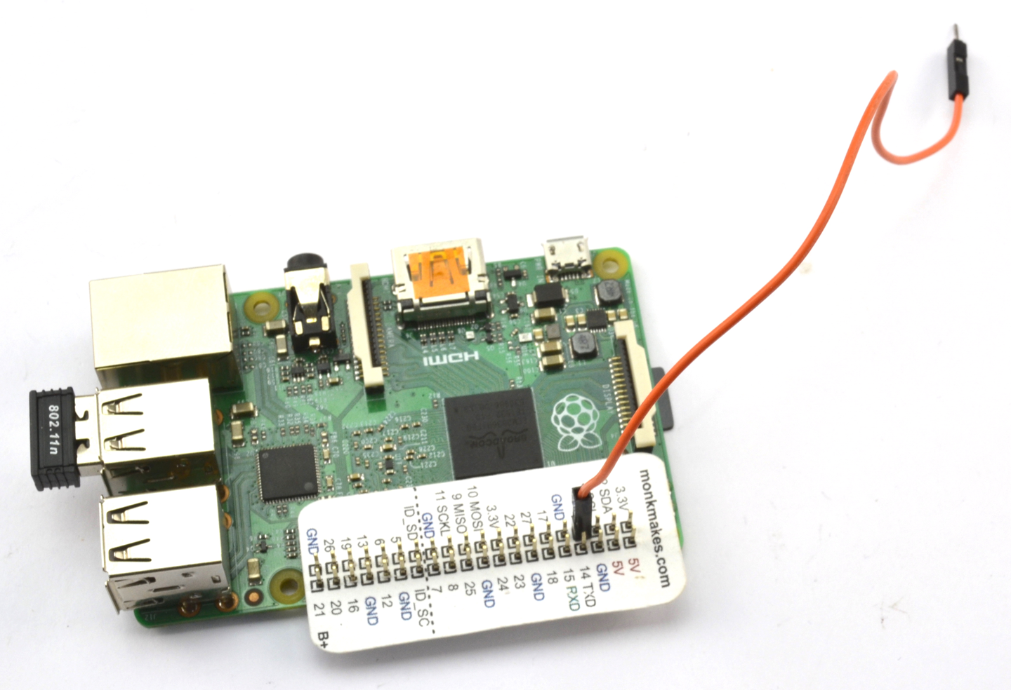
Figure 19-7. A Raspberry PiFM Transmitter
You will now have two executable programs, one called pifm for the Raspberry Pi 1 models and pi2fm for the Raspberry Pi 2 and 3. If you have an original Pi 1 you will need to modify pi2fm to be just pifm in the following commands, which will play the file sound.wav supplied with the pifm software:
pi@raspberrypi:~/pifm $ sudo ./pi2fm sound.wav 94.0
starting...
 -> carrier freq: 94.0 MHz
 -> band width: 8.0
now broadcasting: sound.wav ...
Discussion
Attaching a longer wire to pin 4 will considerably increase the range of the transmitter.
See Also
The original web page for the PiFM project can be found here: http://bit.ly/18AcT5u.
Details on the Raspberry Pi 2 version are here: https://github.com/oatmeal3000/pi2fm.
19.3 Build an Arduino-Powered FM Receiver
Solution
Use a TEA5767 FM radio-receiver module controlled by an Arduino and either connect headphones or use a power amplifier to drive speakers.
Figure 19-8 shows how the module is connected to an Arduino.
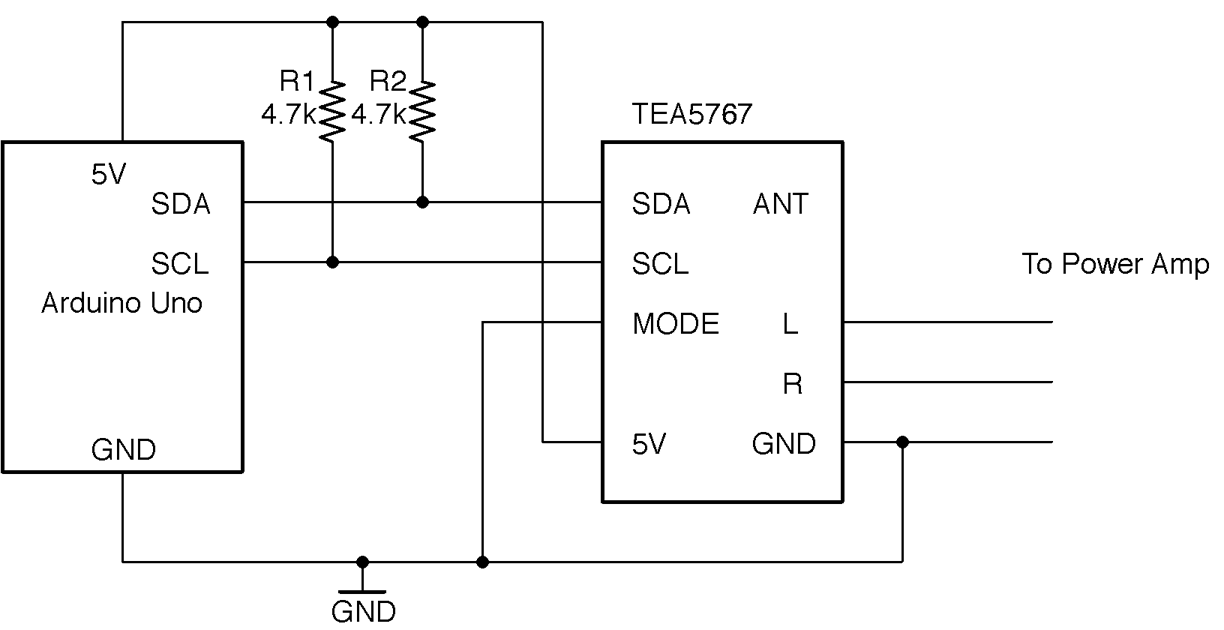
Figure 19-8. Connecting a TEA5767 FM Receiver Module to an Arduino
To make the module as easy to program as possible, download the Arduino TEA5767 library by clicking on Clone or download on GitHub. Select the option to download as a ZIP file and then from the Arduino IDE select the menu option Sketch→Include Library→Add ZIP Library and navigate to the ZIP file you just downloaded.
Discussion
To build a circuit using this module on a breadboard (Figure 19-9), you will need a breakout circuit board that allows you to connect the fine pitch of the module’s connectors to the breadboard. You can make this yourself using stripboard or buy a breakout board from OSHPark or Monk Makes.
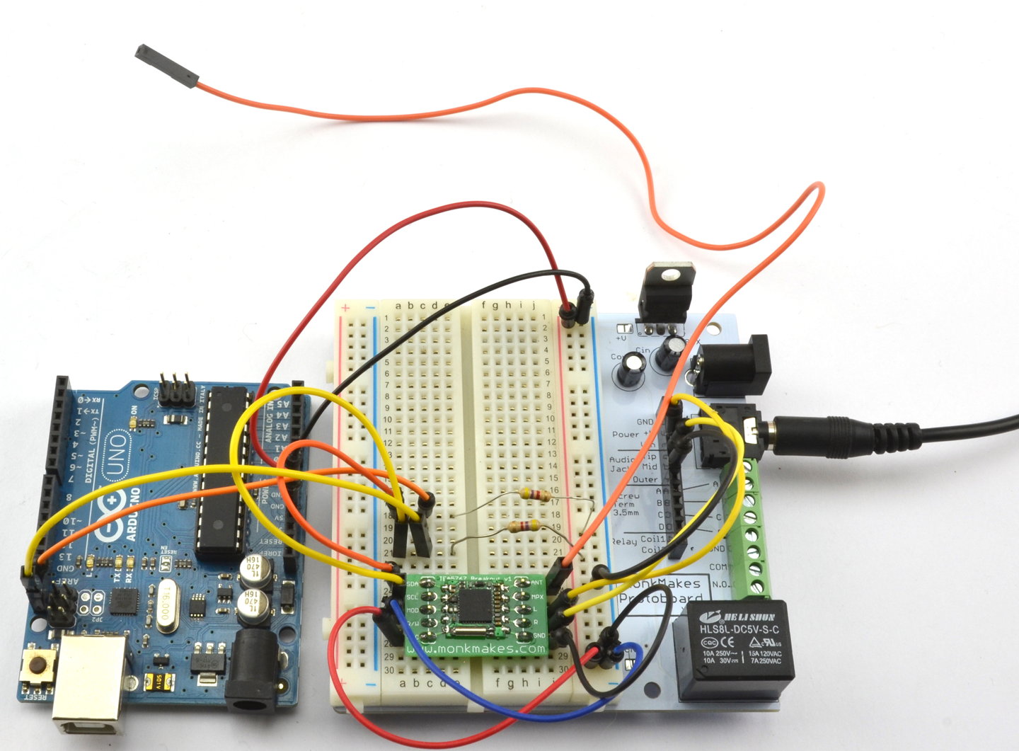
Figure 19-9. An Arduino-Controlled FM Radio on a Breadboard
The sketch ch_19_fm_radio uses the Serial Monitor so that you can enter the frequency you want to tune in to. When using the Serial Monitor with this sketch, make sure the “Line ending” drop-down list is set to “No line ending” before sending a frequency to the Arduino.
The sketch is available with the book downloads (see Recipe 10.2) and is listed here:
#include <Wire.h>#include <TEA5767Radio.h>TEA5767Radioradio=TEA5767Radio();voidsetup(){Serial.begin(9600);Serial.println("Enter Frequency:");Wire.begin();}voidloop(){if(Serial.available()){floatf=Serial.parseFloat();radio.setFrequency(f);Serial.println(f);}}
The setFrequency function accepts a decimal value in MHz (e.g., 93.0).
See Also
To make a suitable power amplifier for this project, see Recipe 18.4 or Recipe 18.5.
For an FM transmitter to accompany this receiver, see Recipe 19.1 or Recipe 19.2.
19.4 Send Digital Data Over a Radio
Solution
Use a CC1101 RF transceiver (transmitter/receiver). These boards are readily available on eBay at very low cost. Figure 19-10 shows how you would wire one up to the SPI interface of an Arduino.
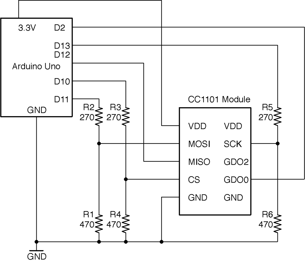
Figure 19-10. Wiring a CC1101 Module to an Arduino
The module is a 3.3V device and the datasheet states that none of the pins should have a voltage of more than 3.9V applied to them, so a level converter should be used on all pins used as inputs to the CC1101. This takes the form of six resistors used in pairs as voltage dividers (see Recipe 2.6).
Discussion
Clearly to test out this recipe, you will need two Arduinos and two CC1101 modules each wired up as shown in Figure 19-11.
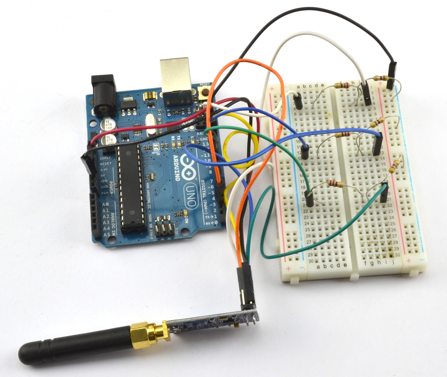
Figure 19-11. An Arduino Uno Wired to a CC1101 Module
Testing the modules can get very confusing because the Arduino IDE can only have one port selected at a time. It’s much easier to find a second computer to use both for programming the transmitter and for running the Serial Monitor.
The library used for these examples should be downloaded as a ZIP file from https://github.com/simonmonk/CC1101_arduino by clicking on the Clone or download button and selecting Download ZIP. Save the ZIP file somewhere and then from the Sketch menu choose Sketch→Include Library→Add ZIP Library and select the ZIP you just downloaded.
The two example programs (one for transmit and one for receive) are the examples that accompany the library, but these can also be downloaded with the downloads for the book (see Recipe 10.2).
Here is the transmitter code (ch_19_cc1101_tx):
#include <ELECHOUSE_CC1101.h>constintn=61;bytebuffer[n]="";voidsetup(){Serial.begin(9600);Serial.println("Set line ending to New Line in Serial Monitor.");Serial.println("Enter Message");ELECHOUSE_cc1101.Init(F_433);// set frequency - F_433, F_868, F_965 MHz}voidloop(){if(Serial.available()){intlen=Serial.readBytesUntil('\n',buffer,n);buffer[len]='\0';Serial.println((char*)buffer);ELECHOUSE_cc1101.SendData(buffer,len);}}
The maximum packet size is 64 bytes and buffer is used to contain the data to be sent, which can by anything you can pack into a byte array. In this case, short text messages.
In the setup function, the communication frequency is set. The Serial Monitor first reminds you to turn line endings on in the Serial Monitor. When you send a message the contents of the message are written into buffer and SendData then used to transmit the message you typed.
The corresponding receiver code can be found in ch_19_cc1101_tx and is listed here:
#include <ELECHOUSE_CC1101.h>constintn=61;voidsetup(){Serial.begin(9600);Serial.println("Rx");ELECHOUSE_cc1101.Init(F_433);// set frequency - F_433, F_868, F_965 MHzELECHOUSE_cc1101.SetReceive();}bytebuffer[61]={0};voidloop(){if(ELECHOUSE_cc1101.CheckReceiveFlag()){intlen=ELECHOUSE_cc1101.ReceiveData(buffer);buffer[len]='\0';Serial.println((char*)buffer);ELECHOUSE_cc1101.SetReceive();}}
This sketch uses CheckReceiveFlag to monitor Arduino pin 2 for the CC1101 to indicate that a new message has arrived. When a message does arrive, it is read into buffer and then displayed in the Serial Monitor. Figures 19-12 and 19-13 show the Serial Monitors of the transmitter and receiver, respectively.
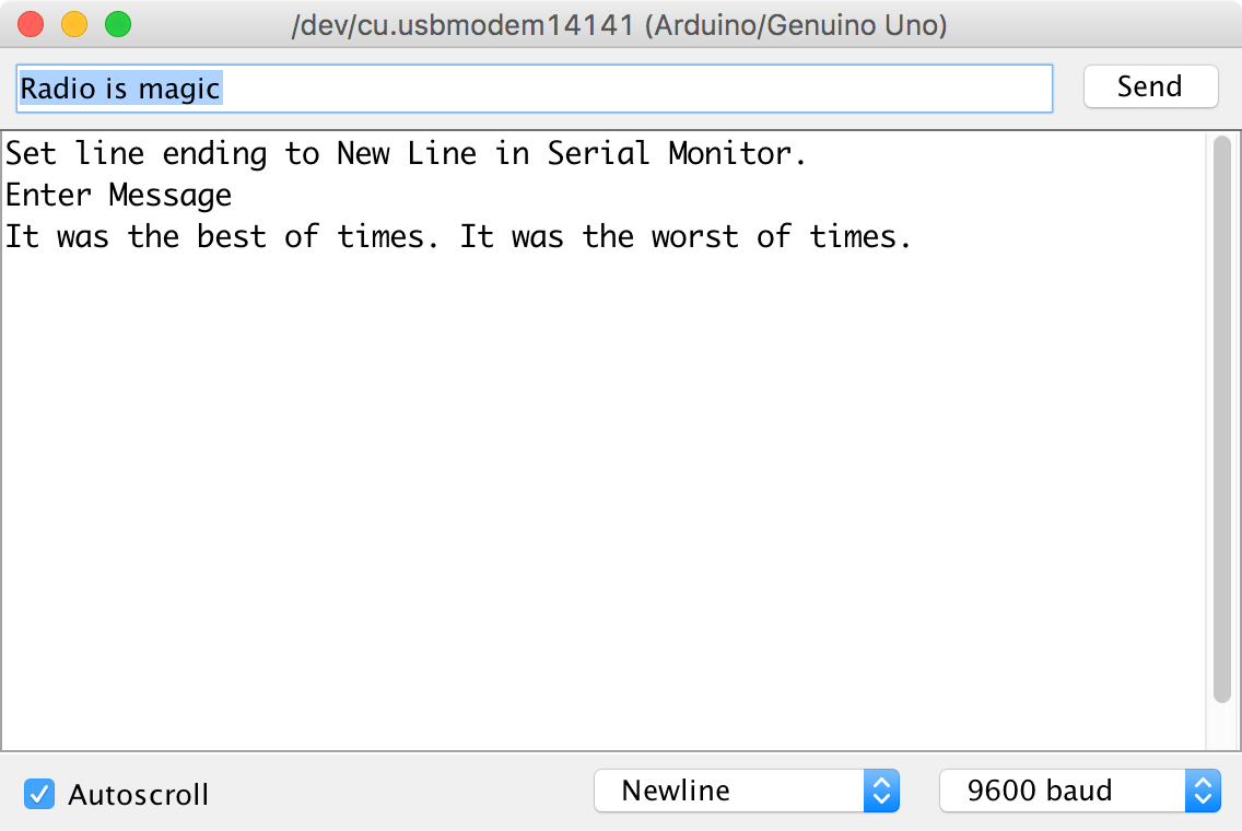
Figure 19-12. Transmitting a Message Using a CC1101 Module
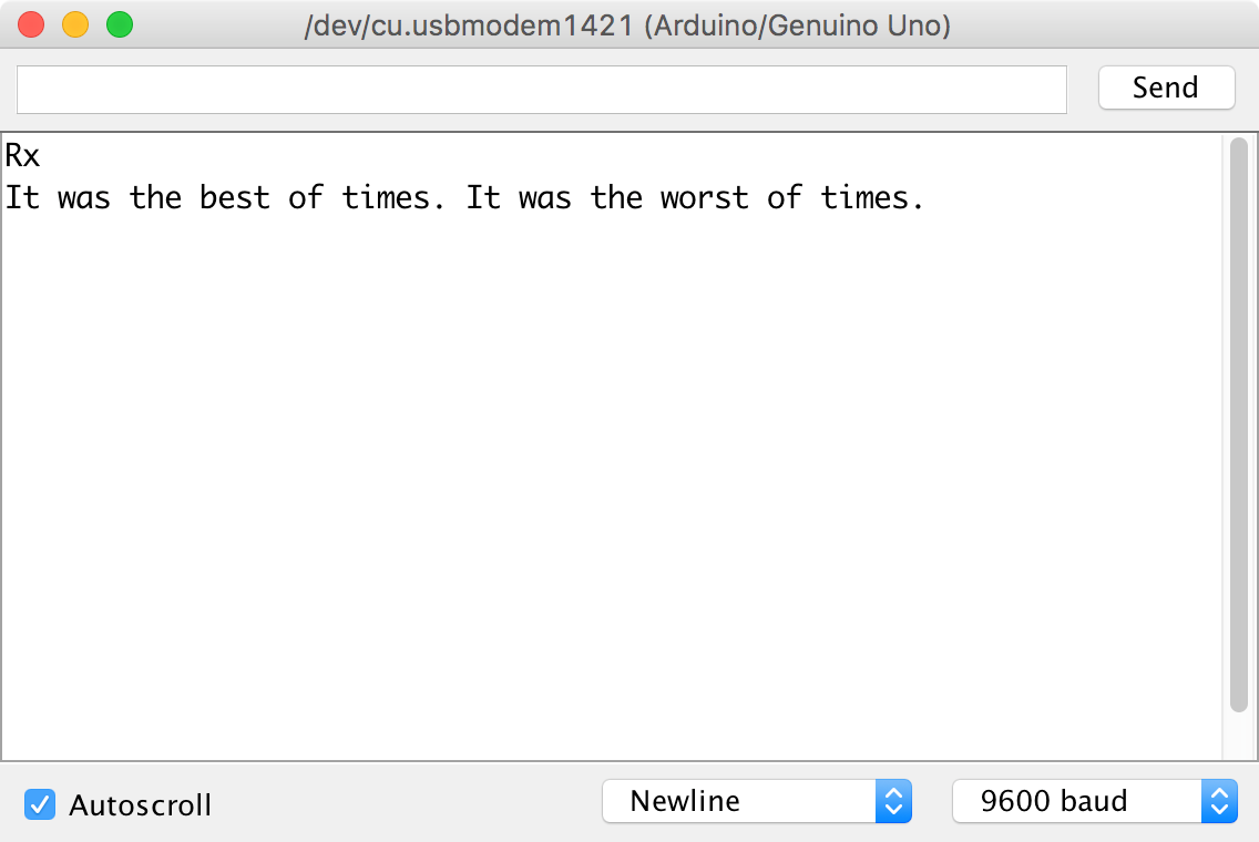
Figure 19-13. Receiving a Message Using a CC1101 Module
See Also
You can find the datasheet for the CC1101 IC here: http://bit.ly/2ltuxK9.
The library used here is modified from that of elechouse.com that also sells CC1101 modules: http://bit.ly/2n3lnQK.