Table of Contents for
Electronics Cookbook
 Electronics Cookbook
Published by
O'Reilly Media, Inc., 2017
Electronics Cookbook
Published by
O'Reilly Media, Inc., 2017
- Cover
- nav
- Electronics Cookbook
- Electronics Cookbook
- Preface
- Theory
- Resistors
- Capacitors and Inductors
- Diodes
- Transistors and Integrated Circuits
- Switches and Relays
- Power Supplies
- Batteries
- Solar Power
- Arduino and Raspberry Pi
- Switching
- Sensors
- Motors
- LEDs and Displays
- Digital ICs
- Analog
- Operational Amplifiers
- Audio
- Radio Frequency
- Construction
- Tools
- Parts and Suppliers
- Arduino Pinouts
- Raspberry Pi Pinouts
- Units and Prefixes
- Index
- About the Author
- Colophon
Chapter 14. LEDs and Displays
14.0 Introduction
LEDs can be used both for illumination and as indicators. They can also be arranged as 7-segment displays or as tiny pixels in an OLED (organic LED) display.
This chapter contains recipes relating to powering and controlling LEDs as well as for using a display with an Arduino or Raspberry Pi.
14.1 Connect Standard LEDs
Solution
Back in Recipe 4.4 you saw how an LED needs a series resistor to prevent too much current from flowing. Too much current will shorten the life of an LED, but more importantly, it may damage or destroy the Arduino or Raspberry Pi GPIO pin that is controlling the LED.
Wire up your LED to a GPIO pin as shown in Figure 14-1 and then use Table 14-1 to select a value for the series resistor.
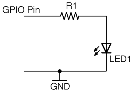
Figure 14-1. Connecting an LED to a GPIO Pin
| Infrared | Red | Orange/Yellow/Green | Blue/White | Violet | UV | |
|---|---|---|---|---|---|---|
| Vf | 1.2-1.6V | 1.6-2V | 2-2.2V | 2.5-3.7V | 2.7-4V | 3.1-4.4V |
| 3.3V GPIO 3mA | 1kΩ | 680Ω | 470Ω | 270Ω | 220Ω | 68Ω |
| 3.3V GPIO 16mA | 150Ω | 120Ω | 82Ω | 56Ω | 39Ω | 15Ω |
| 5V GPIO 20mA | 220Ω | 180Ω | 150Ω | 150Ω | 120Ω | 100Ω |
Discussion
In practice, nearly all LEDs will illuminate to some degree even from 3.3V with a 1kΩ resistor limiting the current. So, as an even broader rule of thumb, if you don’t care about optimizing the brightness of your LED then a 270Ω resistor is fine.
For optimum brightness find the datasheet for your LED and use the forward-voltage Vf and maximum forward current If with the formula in Recipe 4.4 to calculate the optimum value of resistor.
If you connect an LED as shown in Figure 14-1 you can test turning it on and off using an Arduino and Raspberry Pi with Recipe 10.8 and Recipe 10.9.
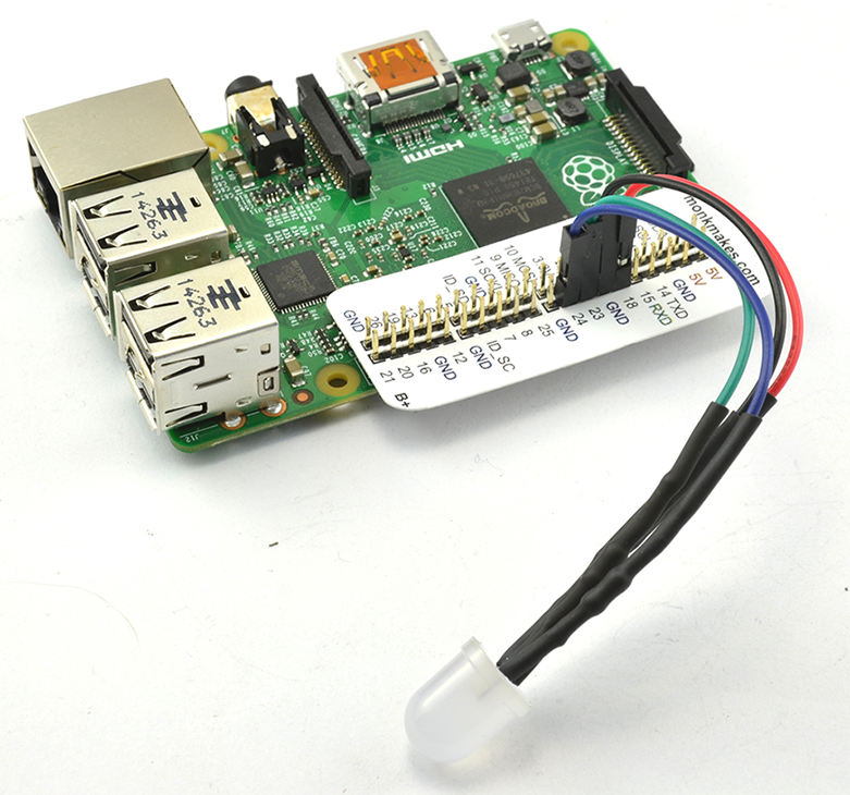
Figure 14-2. A Raspberry Squid RGB LED
A convenient thing to have around if you want to use LEDs with a Raspberry Pi is a Raspberry Squid (Figure 14-2). This has series resistors for the red, green, and blue LEDs built-in to the leads, so you can just plug it straight onto the GPIO connector of a Raspberry Pi.
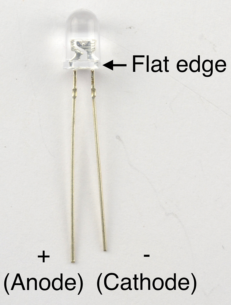
Figure 14-3. A 5mm Through-hole LED
See Also
For more background on LEDs, see Recipe 4.4.
To make your own Raspberry Squid, see https://github.com/simonmonk/squid.
14.2 Drive High-Power LEDs
Solution
Modify Recipe 7.7 to add a control input for the LED driver as shown in Figure 14-4.
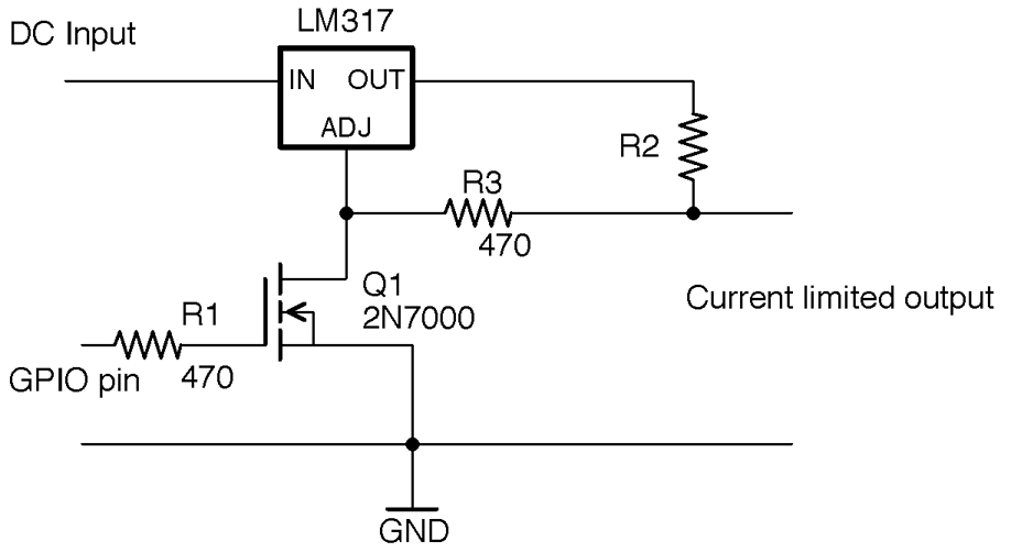
Figure 14-4. Constant-Current LED Control from Arduino or Raspberry Pi
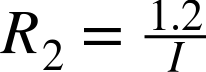
When the GPIO pin is low, Q1 will be off and effectively takes no part in the circuit. The LM317 then acts as a constant-current source where R2 sets the current as discussed in Recipe 7.7 according to the formula:
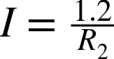
So if you know what current you want to set, you can calculate the value of R2 using:
Since R3 is very low compared to the input impedance of the Adjust pin of the LM317, it can be ignored.
When the GPIO pin is taken above the gate-threshold voltage of Q1, Q1 will turn on, pulling the Adjust pin low and reducing the regulated voltage to 0V.
Discussion
The LM317 will get hot if the DC-input voltage is significantly higher than the forward voltage of the LED. In fact, the power it will turn into heat will be:
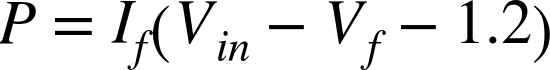
where If is the forward voltage of the LED, Vin is the input voltage, and Vf is the forward voltage of the LED.
R2 will generally be a low-value resistor that will produce heat with a power of:

As an example, Figure 14-5 shows the circuit of Figure 14-4 supplying 120mA to a high-power LED. For this, R2 is a 10Ω 1/4W resistor. The control pin is connected to a GPIO pin of an Arduino.
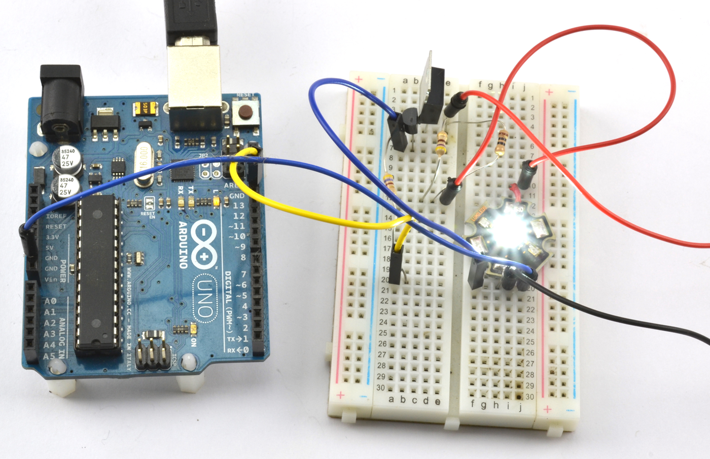
Figure 14-5. Controlling a Constant-Current Source from an Arduino
Arduino software
You can turn the LED on and off using the sketch from Recipe 10.8 but on and off will be swapped over because a HIGH at the GPIO pin will turn the LED off.
You can also use PWM to control the LED brightness, but again, the logic is inverted, so you will need to modify the following line in ch_10_analog_output from:
int brightness = Serial.parseInt();
to be:
int brightness = 255 - Serial.parseInt();
Raspberry Pi software
You can use the Python program from Recipe 10.9, but as with the equivalent Arduino sketch the on/off logic will be inverted.
For brightness control, you will also need to modify the line:
duty = int(duty_s)
to be:
duty = 100 - int(duty_s)
See Also
The LM317 datasheet can be found here: http://www.ti.com/lit/ds/symlink/lm317.pdf.
14.3 Power Lots of LEDs
Solution
Arrange columns of LEDs in series to match the supply voltage, with a current-limiting resistor for each column. The example in Figure 14-6 shows how you could power 20 LEDs with a forward voltage of 1.7V and a forward current of around 20mA from a 12V power supply.
In this case, five forward-biased LEDs in a column will drop a total of 8.5V, leaving 3.5V to be dropped across the resistor. Using Ohm’s Law, this means the resistor should have a value of 175Ω so a standard value of 180Ω would lower the current just slightly but enough.
While it’s tempting to reduce the number of resistors you need by putting more LEDs in series, this can cause practical problems of overcurrent if the stated forward voltage of the LEDs is not quite accurate. As a rule of thumb, I generally like to keep ¼ of the supply voltage for the series resistor.
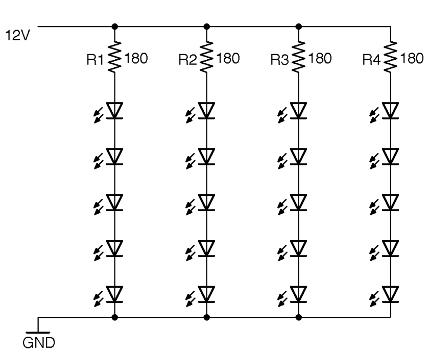
Figure 14-6. Powering Lots of LEDs
Discussion
The extreme version of this design is to power a long series of LEDs directly from mains voltage. It works, but frankly this is just terrifying—don’t do it.
It’s tempting to consider just putting LEDs in series to share a series resistor as shown in Figure 14-7.
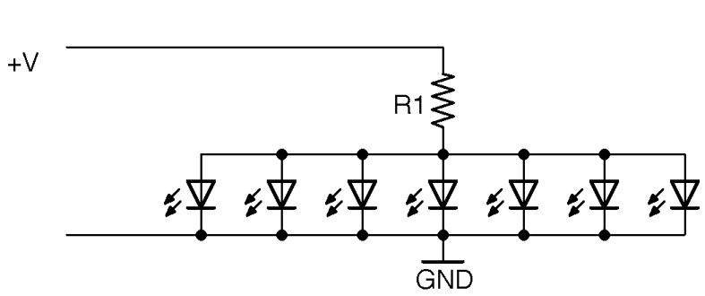
Figure 14-7. An Incorrect Way of Powering LEDs
The problem with doing this is that if there are slight variations in the forward voltage of each LED (which there will be) the LED with the smallest Vf will start conducting first and immediately draw ALL the current from the resistor. This may well burn out the LEDs one at a time.
See Also
For basic information on LEDs and series resistors, see Figure 14-1.
There is a nice online calculator that will do the series resistor calculations for you here: http://led.linear1.org/led.wiz.
14.4 Switch Lots of LEDs at the Same Time
Problem
You have a big bank of LEDs (see Recipe 14.3) and you want to switch them all on and off from an Arduino or Raspberry Pi.
Solution
Switching a big bank of LEDs is really no different from switching any sizeable load. You can use Recipe 13.3 to do this.
For programs to turn the LEDs on and off, you can use Recipe 10.8 and Recipe 10.9.
Discussion
You can also use a PWM signal to control the brightness of a big bank of LEDs using the programs found in Recipe 10.13 and Recipe 10.14.
See Also
See Chapter 11 for a whole load of recipes concerned with switching loads like this.
14.5 Multiplex Signals to 7-Segment Displays
Solution
Use multiplexing—a technique that reduces the number of GPIO pins needed to light lots of LEDs. Figure 14-8 shows how you can control a 4-digit LED display from an Arduino Uno.
Each digit of the display has seven segments in a figure-8 arrangement. Each of these segments is labeled A to G and is connected, inside the LED package, to all the segments of the same name. In this display, all the cathodes of the segments for a particular digit are connected together as a common cathode. The LED display has a pin for each of these four common cathodes so that the software can enable each digit in turn, set its segment pattern, and then move on to the next digit.
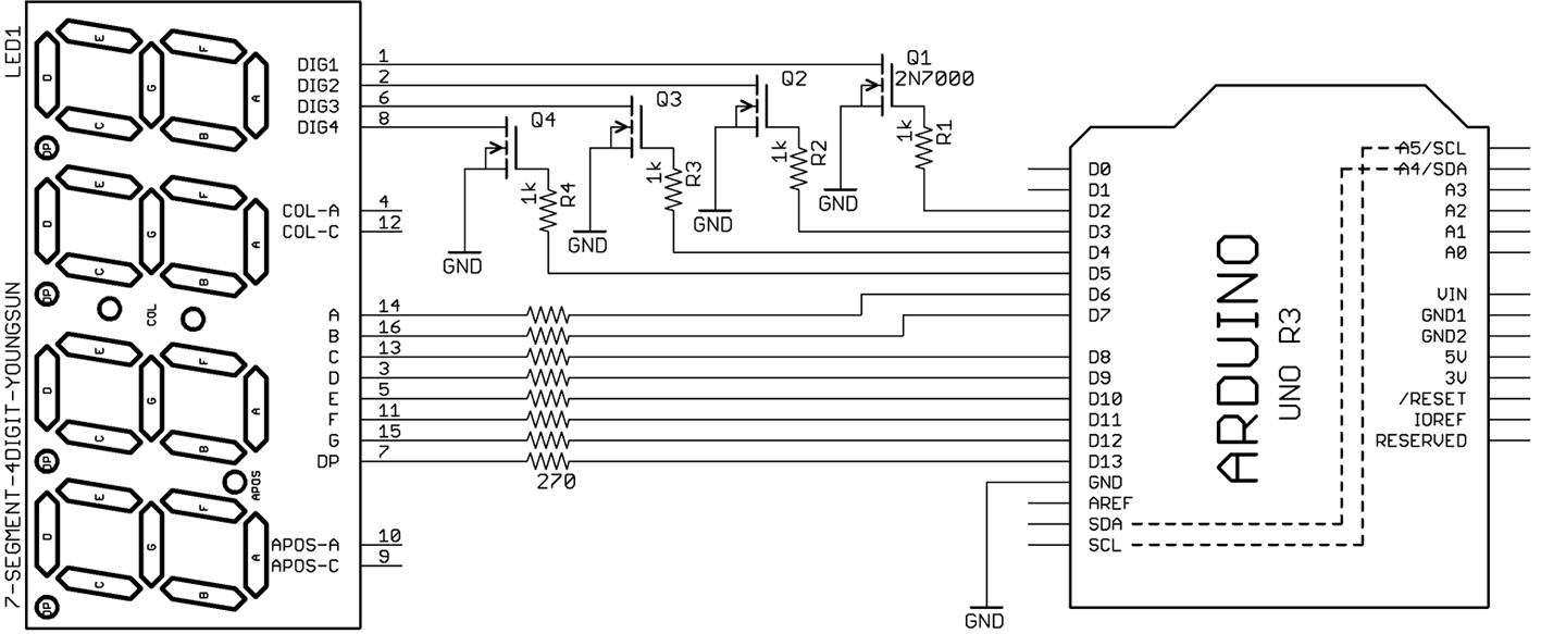
Figure 14-8. Controlling a 4-digit LED Display from an Arduino
The sketch ch_14_7_seg_mux displays the numbers 1 to 4 on the display (see Figure 14-9).
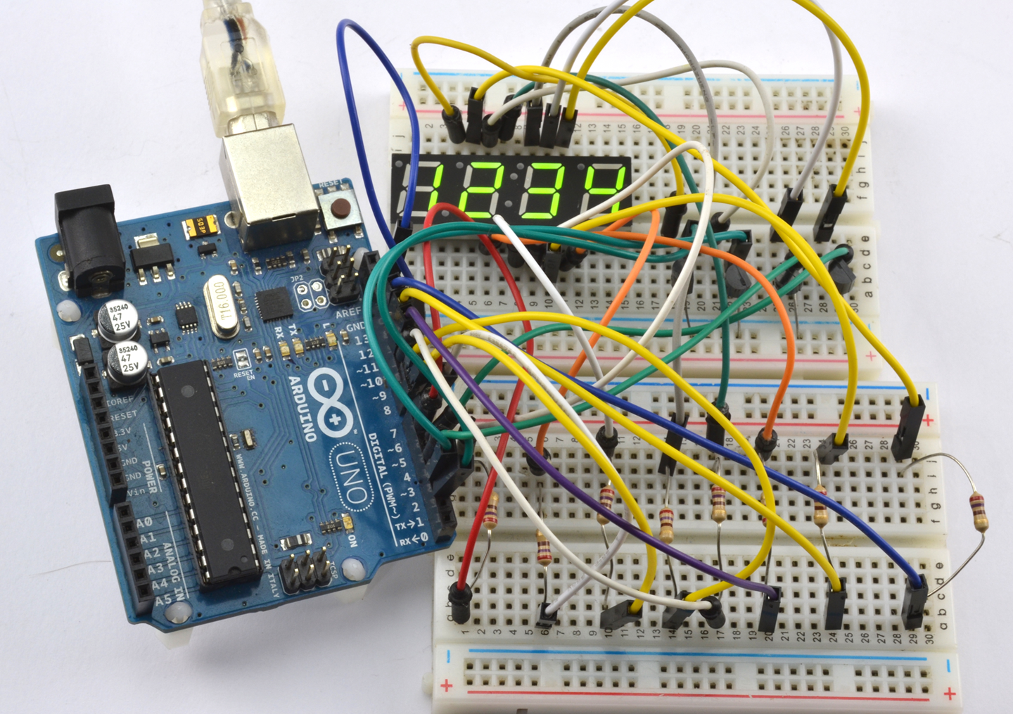
Figure 14-9. Multiplexing a 7-Segment Display on a Breadboard
The sketch can be found with the downloads for the book (see Recipe 10.2):
constintdigitPins[]={2,3,4,5};constintsegPins[]={6,7,8,9,10,11,12,13};// abcdefgDconstcharnum[]={0b11111100,// 0 abcdef0b00001100,// 1 ef0b11011010,// 2 ab de g0b10011110,// 3 a defg0b00101110,// 4 c efg0b10110110,// 5 a cd fg0b11110110,// 6 abcd fg0b00011100,// 7 def0b11111110,// 8 abcdefg0b10111110};// 9 a cdefgintdigits[]={1,2,3,4};voidsetup(){for(inti=0;i<4;i++){pinMode(digitPins[i],OUTPUT);}for(inti=0;i<8;i++){pinMode(segPins[i],OUTPUT);}}voidloop(){refreshDisplay();}voidrefreshDisplay(){for(intd=0;d<4;d++){for(intseg=0;seg<8;seg++){digitalWrite(segPins[seg],LOW);}digitalWrite(digitPins[d],HIGH);for(intseg=0;seg<8;seg++){digitalWrite(segPins[seg],bitRead(num[digits[d]],7-seg));}delay(1);digitalWrite(digitPins[d],LOW);}}
The digit and segment pins are contained in arrays. The setup function sets them all as outputs.
Two other arrays are defined: num contains the bit patterns for the numbers 0 to 9. A 1 in the bit position means the segment should be lit for that value. The array digits holds the numeric value to be displayed on each of the four positions.
Every time the refreshDisplay function is called, all four digits of the display will be displayed and then the display blanked. This means that refreshDisplay must be called as frequently as possible or the display may become flickery or dim. The function has an outer loop that loops for each digit number d between 0 and 3. Inside this loop, the segments are first turned off and then the control pin for the current digit is enabled.
An inner loop then loops for each segment (seg) and determines whether the current segment should be lit or not, based on the expression:
bitRead(num[digits[d]],7-seg)
This first finds the current digit value and then looks up the bit pattern for that value.
Discussion
The critical thing about the preceding example code is that anything that you do inside the loop function along with refreshDisplay must happen quickly, or the display will start to flicker. The human eye will not see the flickering until refreshDisplay is called less frequently than 30 times a second, giving you a theoretical 30 milliseconds (approximately) to do something else in loop. This is more than enough time to check the state of digital inputs and perform other simple actions, but remember—always keep loop as fast as possible.
Figure 14-9 shows that there is quite a lot of wiring involved in multiplexing the display. The same hardware can be attached to the GPIO pins of a Raspberry Pi (at least a 40-pin GPIO Raspberry Pi) but the nature of the operating system means that you might find the refresh a little uneven. For a Raspberry Pi, it is probably better to use a display module that has its own hardware such as the I2C LED display in Recipe 14.9.
See Also
To use an I2C 7-segment LED module, see Recipe 14.9.
14.6 Control Many LEDs
Solution
Use a technique called Charlieplexing.
The name Charlieplexing comes from the inventor Charlie Allen of the company Maxim, and the technique takes advantage of the feature of GPIO pins that allows them to be changed from outputs to inputs while a program is running. When a pin is changed to be an input, not enough current will flow through it to light an LED or influence other pins connected to the LED that are set as outputs.
Figure 14-10 shows the schematic for controlling six LEDs with three pins.
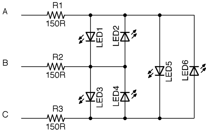
Figure 14-10. Schematic for Charlieplexing Six LEDs
Looking at Figure 14-10, if you want to turn on LED1, you need to make pin A high and B low. But to make sure that none of the other LEDs light, you need to set C to be an input, so that no current can flow into or out of it. More accurately, to make sure that not enough current to light an LED flows into or out of it.
For a small number of LEDs, you can test out Charlieplexing on a breadboard as shown in Figure 14-11.
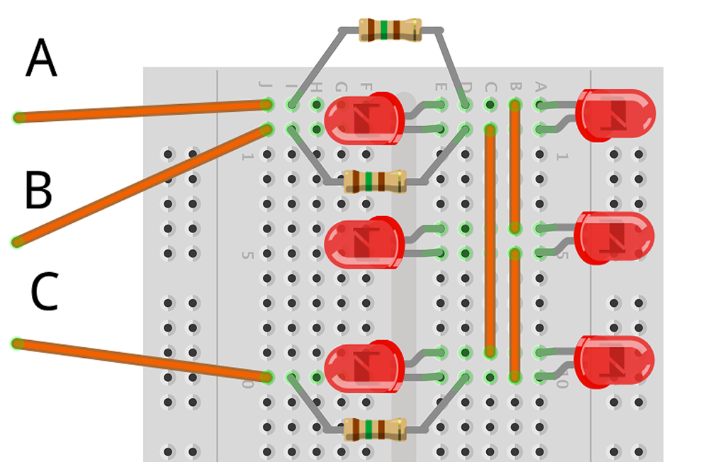
Figure 14-11. Charlieplexing on a Breadboard
Arduino software
Connect the three control points on the breadboard to pins D5, D6, and D7 of your Arduino (D6 to the middle control pin). You can then use the following sketch (ch_14_charlieplexing) to try out Charlieplexing. You will find the sketch with the downloads for the book (see Recipe 10.2):
constintpins[]={5,6,7};constintpinLEDstates[6][3]={{1,0,-1},// LED 1{0,1,-1},// LED 2{-1,1,0},// LED 3{-1,0,1},// LED 4{1,-1,0},// LED 5{0,-1,1}// LED 6};intledState[6];voidsetup(){Serial.begin(9600);Serial.println("LED Number (0 to 5)");}voidloop(){if(Serial.available()){intled=Serial.parseInt();ledState[led]=!ledState[led];}refresh();}voidrefresh(){for(intled=0;led<6;led++){clearPins();if(ledState[led]){setPins(led);}else{clearPins();}delay(1);}}voidsetPins(intled){for(intpin=0;pin<3;pin++){if(pinLEDstates[led][pin]==-1){pinMode(pins[pin],INPUT);}else{pinMode(pins[pin],OUTPUT);digitalWrite(pins[pin],pinLEDstates[led][pin]);}}}voidclearPins(){for(intpin=0;pin<3;pin++){pinMode(pins[pin],INPUT);}}
The key to this code is the pinLEDstates data structure. This specifies the states that the controlling pins should be set to for a particular LED. So, LED3 has the pattern –1, 1, 0. This means that for LED3 to be lit, the first control pin should be set to an input (–1), the second control pin to a HIGH digital output, and the third to a LOW digital output. If you check Figure 14-10 this will confirm those settings.
The loop function first prompts for a particular LED and then toggles that LED turning it on if it was off and off if it was on. The array ledStates is used to keep track of which LEDs should be on or off.
The loop function then calls refresh, which first clears all the pins setting them to inputs using clearPins and then for each of the LEDs uses setPins to either set the pins appropriately to turn the LED on or not depending on that LED’s entry in ledState.
This works fine for a fairly small number of LEDs, assuming that the Arduino is not doing much else, so that refresh can be called frequently. You may have noticed that the LEDs flicker when serial communication is in progress through the Serial Monitor.
Raspberry Pi software
Using a Raspberry Pi instead of an Arduino just requires you to swap the male-to-male header leads to be male-to-female connectors and choose three GPIO pins. In the case of the following example program (ch_14_charlieplexing.py) these should be 18, 23, and 24. You should also increase the value of the resistors to 270Ω.
You can find the program with the downloads for the book (see Recipe 10.4):
importRPi.GPIOasGPIOimportthread,timeGPIO.setmode(GPIO.BCM)pins=[18,23,24]pin_led_states=[[1,0,-1],# LED1[0,1,-1],# LED2[-1,1,0],# LED3[-1,0,1],# LED4[1,-1,0],# LED5[0,-1,1]# LED6]led_states=[0,0,0,0,0,0]defset_pins(led):forpininrange(0,3):ifpin_led_states[led][pin]==-1:GPIO.setup(pins[pin],GPIO.IN)else:GPIO.setup(pins[pin],GPIO.OUT)GPIO.output(pins[pin],pin_led_states[led][pin])defclear_pins():forpininrange(0,3):GPIO.setup(pins[pin],GPIO.IN)defrefresh():whileTrue:forledinrange(0,6):clear_pins()ifled_states[led]:set_pins(led)else:clear_pins()time.sleep(0.001)thread.start_new_thread(refresh,())whileTrue:x=int(raw_input("Pin (0 to 5) :"))led_states[x]=notled_states[x]
The Raspberry Pi version follows the same pattern as the Arduino version except that the call to refresh is in a separate thread of execution, so the display will automatically update, even if the Python program is waiting for input.
Discussion
The number of LEDs that can be controlled for the number of GPIO pins (n) used is given by the formula:

Using four pins, you can have 16–4 = 12 LEDs, whereas 10 pins would give you a massive 90 LEDs.
See Also
For a great description of Charlieplexing as well as layouts for large numbers of LEDs, see https://en.wikipedia.org/wiki/Charlieplexing.
14.7 Change the Colors of RGB LEDs
Solution
Wire up a common-cathode RGB LED as shown in Figure 14-12.
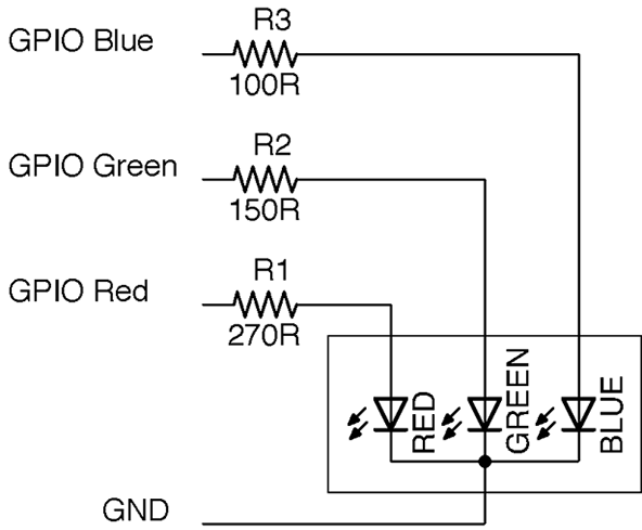
Figure 14-12. Wiring up an RGB LED
The red, green, and blue LEDs, in this example, all have different values of series resistor to try and provide equal brightness. The three LED channels can either be simply turned on and off to mix seven different colors from the three control pins, or you can use PWM on the pins to mix more subtle colors.
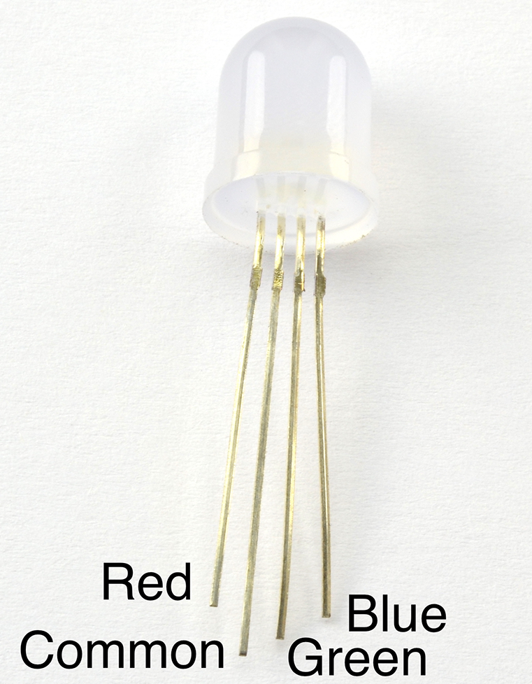
Figure 14-13. RGB LED Pins
Arduino software
Connect an RGB LED to an Arduino as shown in Figure 14-12 using the three Arduino pins 9, 10, and 11 for the blue, green, and red channels, respectively.
The following sketch can be found with the downloads for the book (Recipe 10.2) and is called ch_14_rgb_led:
constintredPin=11;constintgreenPin=10;constintbluePin=9;voidsetup(){pinMode(redPin,OUTPUT);pinMode(greenPin,OUTPUT);pinMode(bluePin,OUTPUT);Serial.begin(9600);Serial.println("Enter R G B (E.g. 255 100 200)");}voidloop(){if(Serial.available()){intred=Serial.parseInt();intgreen=Serial.parseInt();intblue=Serial.parseInt();analogWrite(redPin,red);analogWrite(greenPin,green);analogWrite(bluePin,blue);}}
By sending three numbers separated by spaces from the Arduino Serial Monitor, you can mix pretty much any color from the LED.
Raspberry Pi software
When using a Raspberry Pi, you can follow the same approach of creating three PWM channels using the RPi.GPIO library (see Recipe 10.14) or, as in the following example, you can install the Python Squid library, which simplifies the process.
To install the Squid library, run the following commands:
$ git clone https://github.com/simonmonk/squid.git
$ cd squid
$ sudo python setup.py install
The equivalent program for controlling the RGB LED from a Raspberry Pi can be a little fancier and use the Tkinter Python library to make a user interface that allows you to use sliders to adjust the red, green, and blue channels (Figure 14-14):
fromsquidimport*fromTkinterimport*rgb=Squid(18,23,24)classApp:def__init__(self,master):frame=Frame(master)frame.pack()Label(frame,text='Red').grid(row=0,column=0)Label(frame,text='Green').grid(row=1,column=0)Label(frame,text='Blue').grid(row=2,column=0)scaleRed=Scale(frame,from_=0,to=100,orient=HORIZONTAL,command=self.updateRed)scaleRed.grid(row=0,column=1)scaleGreen=Scale(frame,from_=0,to=100,orient=HORIZONTAL,command=self.updateGreen)scaleGreen.grid(row=1,column=1)scaleBlue=Scale(frame,from_=0,to=100,orient=HORIZONTAL,command=self.updateBlue)scaleBlue.grid(row=2,column=1)defupdateRed(self,duty):rgb.set_red(float(duty))defupdateGreen(self,duty):rgb.set_green(float(duty))defupdateBlue(self,duty):rgb.set_blue(float(duty))root=Tk()root.wm_title('RGB LED Control')app=App(root)root.geometry("200x150+0+0")root.mainloop()
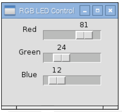
Figure 14-14. Adjusting the RGB LED Color Using a User Interface
Discussion
The LED in Figure 14-12 is a common cathode device; that is, all the negative terminals (cathodes) of the LEDs are connected together. RGB LEDs are also available in common anode form, which can sometimes be more convenient if they are being controlled by transistors as it allows low-side switching.
See Also
For recipes on PWM for Arduino and Raspberry Pi, see Recipe 10.13 and Recipe 10.14, respectively.
The easiest way to control large numbers of RGB LEDs is to use addressable LED strips as described in Recipe 14.8.
14.8 Connect to Addressable LED Strips
Solution
Do the power calculations carefully for your pixels and then use a single GPIO pin to send the data to the pixel array. Figure 14-15 shows a typical arrangement for a large number of pixels. If you only have a few pixels (say 5–10), you can power them directly from your Arduino or Raspberry Pi.
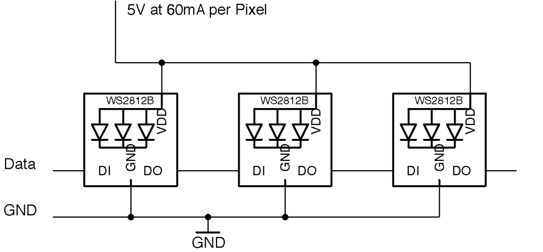
Figure 14-15. Schematic for Using WS2812 Addressable LED Strips
If you don’t mind taking the risk of damaging your Pi, Arduino, or whatever is supplying USB power to them, you can power more pixels as long as you are extremely careful in your code to keep the brightness of the pixels well below the maximum brightness. However, this is not recommended.
Arduino software
To test out an addressable LED strip with an Arduino, connect pin D9 to the data terminal of an addressable LED strip.
The Arduino sketch ch_14_neopixel is included in the downloads for the book (see Recipe 10.2). The sketch uses the Adafruit NeoPixel library. This can be installed from within the Arduino IDE using the Library Manager by selecting the menu option Sketch→Include Library→Manage Libraries.
Once the Library Manager is open scroll down and select Adafruit NeoPixel and then click Install.
#include <Adafruit_NeoPixel.h>constintpixelPin=9;constintnumPixels=10;Adafruit_NeoPixelpixels=Adafruit_NeoPixel(numPixels,pixelPin,NEO_GRB+NEO_KHZ800);voidsetup(){pixels.begin();}voidloop(){for(inti=0;i<numPixels;i++){intred=random(64);intgreen=random(64);intblue=random(64);pixels.setPixelColor(i,pixels.Color(red,green,blue));pixels.show();}delay(100);}
Change the values of pixelPin and numPixels to match the GPIO pin you are using and the number of pixels in your strip.
Each pixel will be allocated red, green, and blue intensities at random. Note that the maximum of 64 is used rather than the full range of 0 to 255 because an intensity of 255 is actually very bright.
Raspberry Pi software
To test out an addressable LED strip with Raspberry Pi, connect GPIO10 to the data terminal of an addressable LED strip.
To use the display, you first need to install some libraries by running the following commands:
$ git clone https://github.com/doceme/py-spidev.git
$ cd py-spidev/
$ make
$ sudo make install
$ cd ..
$ git clone https://github.com/joosteto/ws2812-spi.git
$ cd ws2812-spi
$ sudo python setup.py install
You still also need to enable SPI on your Raspberry Pi (see Recipe 10.16).
You can find a program to test out the LED display in the file ch_14_neopixels.py. See Recipe 10.4 for information on downloading the Python example programs.
importspidevimportws2812fromrandomimportrandintimporttimespi=spidev.SpiDev()spi.open(0,0)N=10# g r bpixels=[]forxinrange(0,10):pixels.append([0,0,0])whileTrue:foriinrange(0,N):pixels[i]=[randint(0,64),randint(0,64),randint(0,64)]ws2812.write2812(spi,pixels)time.sleep(0.1)
Each pixel is represented in an array of three values. These are in order green, red, and blue rather than the more usual red, green, blue. That’s just how the library is. An array (pixels) of N elements where N is the number of pixels is created by using a for loop to append N arrays of green, red, and blue to the pixels array.
The main loop acts just like its Arduino counterpart. It allocates color intensities at random to each pixel position before using the ws2812 library to write out the pixels to the GPIO pin.
Discussion
If you are using a Raspberry Pi, then you may need to level shift the data output (Recipe 10.17), although I have never found this to be necessary in practice. Looking at the datasheet for the WS2812, the minimum input voltage to count as a logical HIGH is 0.7 times the supply voltage (5V). This gives a theoretical value of 3.5V.
You can make a convenient display to attach to an Arduino or Raspberry Pi by sacrificing jumper leads by snipping off one connector and soldering the wire to the LED strip. Figure 14-16 shows such a display connected to a Raspberry Pi. Note the use of the heat-shrink sleave to help stop the solder joints from flexing.
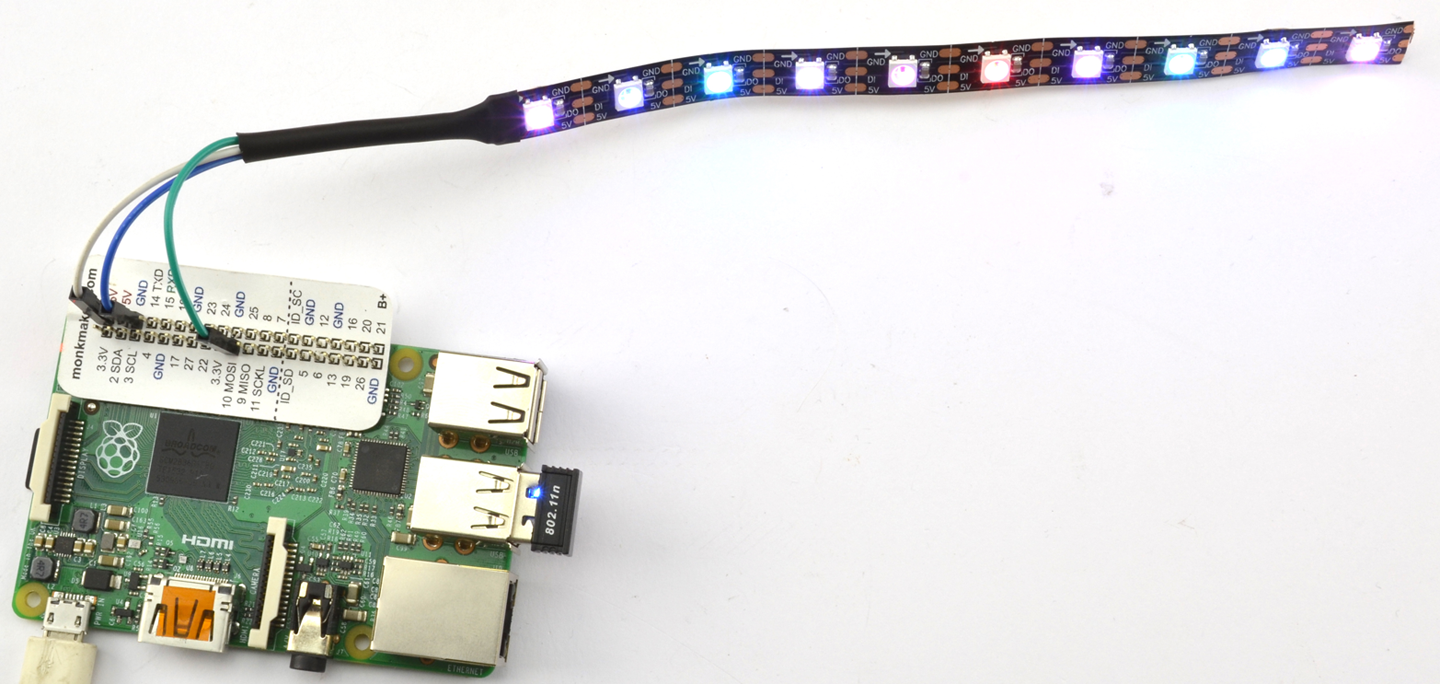
Figure 14-16. A Handy Addressable Pixel Display
See Also
For more information on the ws2812-spi library, see https://github.com/joosteto/ws2812-spi, including instructions on using the NumPy library to improve performance for long LED strings.
You can find the datasheet for the WS2812 here: https://cdn-shop.adafruit.com/datasheets/WS2812.pdf.
To control a single RGB LED directly, see Recipe 14.7.
Addressable LED pixels are not confined to strips of LEDs; you can also buy them organized into rings (Adafruit product 1586) and arrays (Adafruit product 1487).
An alternative library that is based on the Raspberry Pi’s DMA hardware rather than its SPI can be found here: https://github.com/richardghirst.
14.9 Use an I2C 7-Segment LED Display
Problem
You want to use a 7-segment display but without the spaghetti wiring of Recipe 14.5.
Solution
Use a ready-made I2C display module like the one shown in Figure 14-17.
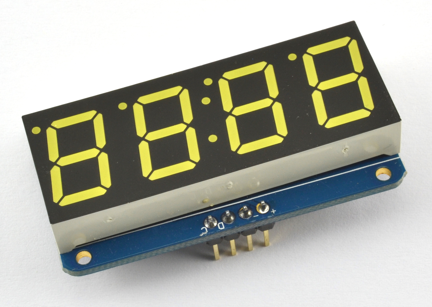
Figure 14-17. An Adafruit 7-Segment Display
This module and similar modules that can be found on eBay, with four or even eight digits, are a convenient way to add a 7-segment LED display to an Arduino or Raspberry Pi.
Figure 14-18 shows how to wire one up using two GPIO pins.
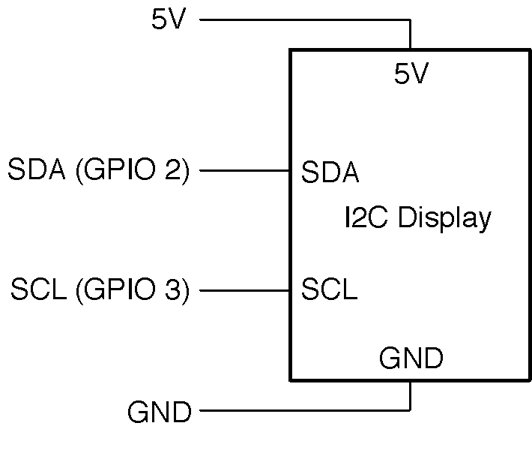
Figure 14-18. Connecting an I2C Display to an Arduino or Raspberry Pi
The I2C serial interface needs two data pins as well as 5V of power. On both the Arduino and Raspberry Pi, specific pins must be used for the I2C interface. On the Arduino Uno, these are the SCL (serial clock) and SDA (serial data) pins (see Recipe 10.7) and on a Raspberry Pi, these are GPIO2 and GPIO3.
This display and many types of displays like it use the HT16K33 IC, which can actually control up to 16 segments in 8 digits. Although the module needs to be powered with 5V, its I2C interface works fine from 3.3V Raspberry Pi GPIO pins, so no level conversion is necessary.
Arduino software
The sketch uses the Adafruit LED Backpack library and Adafruit GFX library. These can be installed from within the Arduino IDE using the Library Manager by selecting the menu option Sketch→Include Library→Manage Libraries.
Once the Library Manager has opened scroll down and select the two libraries and and then click Install.
Adafruit provides a whole load of examples for using the library that you can access directly from the Arduino IDE. A good example to try out can be found under the menu item File→Examples→Adafruit Backpack Library→sevenseg.
Raspberry Pi software
The connections between the Raspberry Pi and the module are as follows:
- VCC (+) on the display to 5V on the Raspberry Pi GPIO connector
- GND (–) on the display to GND on the Raspberry Pi GPIO connector
- SDA (D) on the display to GPIO 2 (SDA) on the Raspberry Pi GPIO connector
- SCL (C) on the display to GPIO 3 (SCL) on the Raspberry Pi GPIO connector
VCC is the abbreviation for volts collector collector, and is frequently used to identify the positive power supply pin of an IC or module.
Before you can use the display, you will need to enable the Raspberry Pi’s I2C interface by following Recipe 10.15.
Adafruit also provides Python code for this module. To install it, enter the following commands into the terminal:
$ sudo apt-get update
$ sudo apt-get install build-essential python-dev
$ sudo apt-get install python-imaging
$ git clone https://github.com/adafruit/Adafruit_Python_LED_Backpack.git
$ cd Adafruit_Python_LED_Backpack
$ sudo python setup.py install
A good example to try out is the clock example sevensegment_test.py.
Discussion
Building a project using a module like this is fine when you are developing a prototype, but in a finished product, you would most likely use direct multiplexing as described in Recipe 14.5 (to reduce costs) or use the HT16K33 IC on a circuit board of your own design, if you really need a hardware driver.

Figure 14-19. Using Solder Switches to Select the Address of an I2C Module
See Also
You can find lots more information on this display at its project page on Adafruit.
To control a similar display but using multiplexing, see Recipe 14.5.
You can download the HT16K33 datasheet from http://bit.ly/2mbaWyP.
14.10 Display Graphics or Text on OLED Displays
Solution
Use an I2C OLED display like the one shown attached to an Arduino in Figure 14-20.
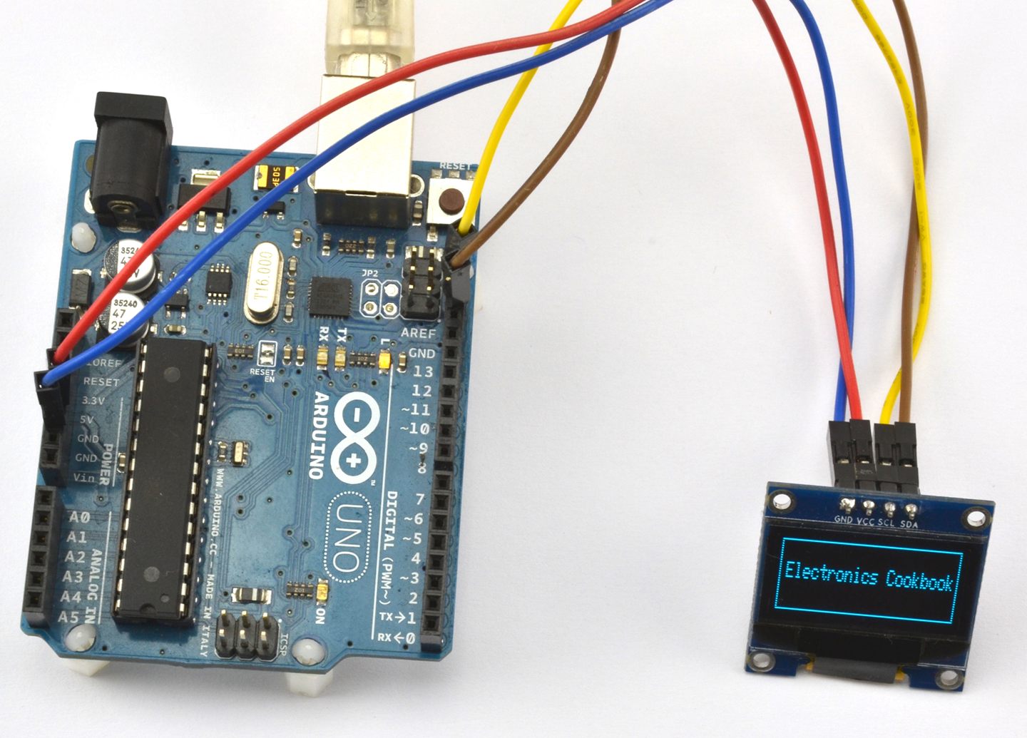
Figure 14-20. An I2C OLED Display Attached to an Arduino
The display has the same four connections as the display used in Recipe 14.9 so you can make the same connections as shown in Figure 14-18.
Arduino software
Wire up the display as described in Recipe 14.9.
You will also need to add the Adafruit GFX and SSD1306 libraries to your Arduino IDE by using the Library Manager (from the menu Sketch→Include Library→Library Manager and then scroll down the list and install both the Adafruit GFX Library and the Adafruit SSD1306 library).
The example sketch ch_14_oled will display the message shown in Figure 14-20. To install the Arduino programs for the book, see Recipe 10.2.
#include <Wire.h>#include <Adafruit_GFX.h>#include <Adafruit_SSD1306.h>Adafruit_SSD1306display(4);voidsetup(){display.begin(SSD1306_SWITCHCAPVCC,0x3c);display.clearDisplay();display.drawRect(0,0,display.width()-1,display.height()-1,WHITE);display.setTextSize(1);display.setTextColor(WHITE);display.setCursor(5,10);display.("Electronics Cookbook");display.display();}voidloop(){}
Raspberry Pi software
Wire up the display as described in Recipe 14.9.
Before you can use the display, you will need to enable the Raspberry Pi’s I2C interface by following Recipe 10.15.
You will also need to download and install the SSD1306 Python library and prerequisites using the following commands:
$ sudo pip install pillow
$ git clone https://github.com/rm-hull/ssd1306.git
$ cd ssd1306
$ sudo python setup.py install
Now change the directory to the book’s example programs and run the program ch_14_oled.py (see Recipe 10.4). The text “Electronics Cookbook” with a rectangular border should appear on the display. If it doesn’t, then there is a good chance you will need to change the I2C address of the device in the file demo_opts.py that is with the other downloads. Change line 13 from 0x3c to the I2C address of your device. The file ch_14_oled.py is listed here:
fromdemo_optsimportdevicefromoled.renderimportcanvasfromPILimportImageFontfromdemo_optsimportargsfont=ImageFont.load_default()withcanvas(device)asdraw:draw.rectangle((0,0,device.width-1,device.height-1),outline=255,fill=0)font=ImageFont.load_default()draw.text((5,20),'Electronics Cookbook',font=font,fill=255)
Discussion
Once you get into the realm of needing a display that can show text and graphics, you can of course use an HDMI monitor with your Raspberry Pi.
See Also
For a simple numeric display see Recipe 14.9 and for a low-cost two-line alphanumeric display see Recipe 14.11.
The SSD1306 library page on GitHub has more examples and documentation for using these displays: https://github.com/rm-hull/ssd1306.
14.11 Display Text on Alphanumeric LCD Displays
Solution
Use an LCD module based on the HD44780 IC. Figure 14-21 shows one of these displays wired to an Arduino and Figure 14-22 shows how the display should be connected on a breadboard. Figure 14-23 shows the connections for a Raspberry Pi as a schematic.
The HD44780 can be configured to use either an 4- or 8-bit parallel data bus. If the 4-bit bus is used only bits 4 to 7 of the bus are used. The pin Vo is used to control the contrast of the screen. You will need to adjust R1 to be able to see anything on the screen.
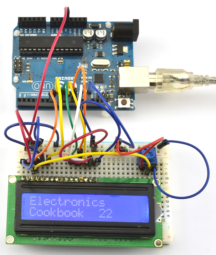
Figure 14-21. An HD44780 16x2 LCD Display Connected to an Arduino
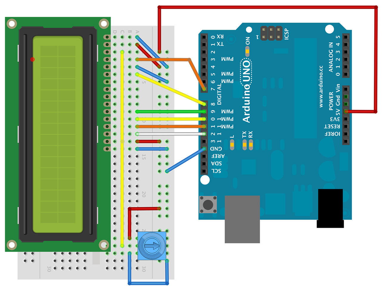
Figure 14-22. Wiring an HD44780 Display to an Arduino Uno (Breadboard)
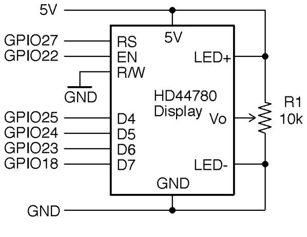
Figure 14-23. Wiring an HD44780 Display to a Raspberry Pi
Arduino software
The Arduino IDE includes a library called LiquidCrystal that takes care of all the communications with the HD44780 IC. The following example can be found with the Arduino downloads for the book (Recipe 12.2) in the sketch ch_14_lcd:
#include <LiquidCrystal.h>// RS EN D4 D5 D6 D7LiquidCrystallcd(7,8,9,10,11,12);voidsetup(){lcd.begin(16,2);lcd.("Electronics");lcd.setCursor(0,1);lcd.("Cookbook");}voidloop(){lcd.setCursor(10,1);lcd.(millis()/1000);}
Raspberry Pi software
To use an HD44780 display on a Raspberry Pi, you will first need to install the Adafruit CharLCD Python library by entering the following commands:
$ git clone https://github.com/adafruit/Adafruit_Python_CharLCD.git
$ cd Adafruit_Python_CharLCD
$ sudo python setup.py install
You can now try out the example program ch_14_lcd.py:
importtimeimportAdafruit_CharLCDasLCD# Raspberry Pi pin configuration:lcd_rs=27# Note this needs to be changed to 21 for Model B rev1 Pis.lcd_en=22lcd_d4=25lcd_d5=24lcd_d6=23lcd_d7=18lcd_backlight=4lcd_columns=16lcd_rows=2lcd=LCD.Adafruit_CharLCD(lcd_rs,lcd_en,lcd_d4,lcd_d5,lcd_d6,lcd_d7,lcd_columns,lcd_rows,lcd_backlight)lcd.message('Electyronics\nCookbook')t0=time.time()whileTrue:lcd.set_cursor(10,1)lcd.message(str(int(time.time()-t0)))time.sleep(0.1)
See Also
Adafruit has a wide selection of these types of displays, including ones that have an RGB color backlight (https://www.adafruit.com/products/399).