Table of Contents for
Electronics Cookbook
 Electronics Cookbook
Published by
O'Reilly Media, Inc., 2017
Electronics Cookbook
Published by
O'Reilly Media, Inc., 2017
- Cover
- nav
- Electronics Cookbook
- Electronics Cookbook
- Preface
- Theory
- Resistors
- Capacitors and Inductors
- Diodes
- Transistors and Integrated Circuits
- Switches and Relays
- Power Supplies
- Batteries
- Solar Power
- Arduino and Raspberry Pi
- Switching
- Sensors
- Motors
- LEDs and Displays
- Digital ICs
- Analog
- Operational Amplifiers
- Audio
- Radio Frequency
- Construction
- Tools
- Parts and Suppliers
- Arduino Pinouts
- Raspberry Pi Pinouts
- Units and Prefixes
- Index
- About the Author
- Colophon
Chapter 3. Capacitors and Inductors
3.0 Introduction
When it comes to digital electronics, capacitors are almost a matter of insurance, providing short-term stores of charge that improve the reliability of circuits. As such their use is often simply a matter of following the recommendations in the IC’s datasheet without the need to do any math.
However, when it comes to analog electronics the use of capacitors becomes much more varied. Their ability to store small amounts of charge for a short period of time can be used to set the frequency of oscillators (see Recipe 16.5). They can be used to smooth the ripples for a power supply (see Recipe 7.2) or to couple two audio circuits without transferring the DC part of the signal (see Recipe 17.9).
In fact, capacitors will be used throughout this book in all sorts of ways, so it’s important to understand how they work, how to select the right capacitor, and how to use it.
Inductors are not as common as capacitors, but they are widely used in certain roles, particularly in power supplies (see Chapter 7).
3.1 Store Energy Temporarily in Your Circuits
Solution
Use a capacitor.
In construction, capacitors are just two conductive surfaces separated by an insulating layer (Figure 3-1).
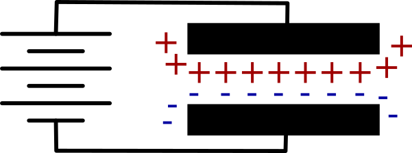
Figure 3-1. A Capacitor
In fact, the insulating layer between the conductive surfaces of the capacitor can just be air, although a capacitor using an air gap will be of very low value. In fact, the value of the capacitor depends on the area of the conducting plates, how close they are together, and how good an insulator separates them. So the greater the area of the plates and the smaller the distance between them the greater the capacitance (the more charge it can store).
Individual electrons do not flow through a capacitor, but those on one side of the capacitor influence those on the other. If you apply a voltage source like a battery to a capacitor, then the plate of the capacitor connected to the positive supply of the battery will accumulate positive charge and the electric field this generates will create a negative charge of equal magnitude on the opposite plate.
In water terms, you can think of a capacitor as an elastic membrane in a pipe (Figure 3-2) that does not allow water to pass all the way through the pipe, but will stretch, allowing the capacitor to be charged. If the capacitor is stretched too far then the elastic membrane will rupture. This is why exceeding the maximum voltage of a capacitor is likely to destroy it.
Discussion
When you apply a voltage across a capacitor it will almost instantly charge to that voltage. But if you charge it through a resistor then it will take time to become full of charge. Figure 3-3 shows how a capacitor can be charged or discharged through the use of the switches S1 and S2.
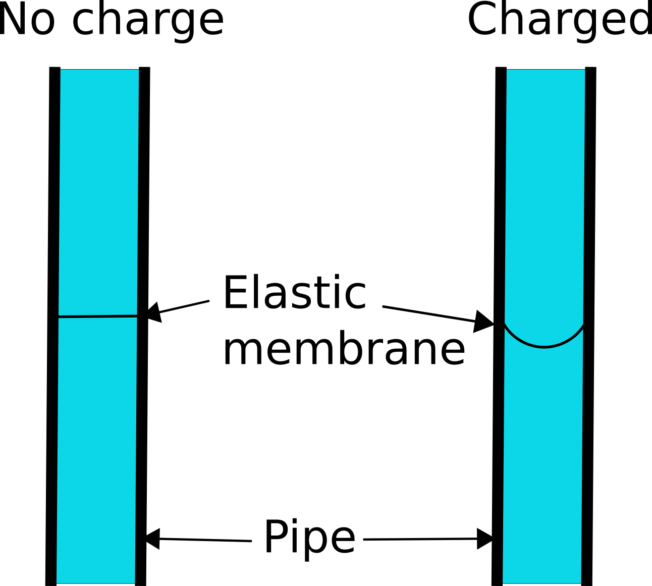
Figure 3-2. Water and Pipe Analogy for a Capacitor
Figure 3-3. Charging and Discharging a Capacitor
When you close switch S1, C1 will charge through R1 until C1 reaches the battery voltage. Open S1 again and the now charged capacitor will retain its charge. Eventually the capacitor will lose its charge through self-discharge.
If you now close S2, C1 will now discharge through R2 and LED1, which will light brightly at first and then more dimly as C1 is discharged.
If you want to experiment with the schematic diagram of Figure 3-3, then build up the breadboard diagram shown in Figure 3-4. For an introduction to breadboard, see Recipe 20.1. Use 1kΩ resistors and a 100µF capacitor.
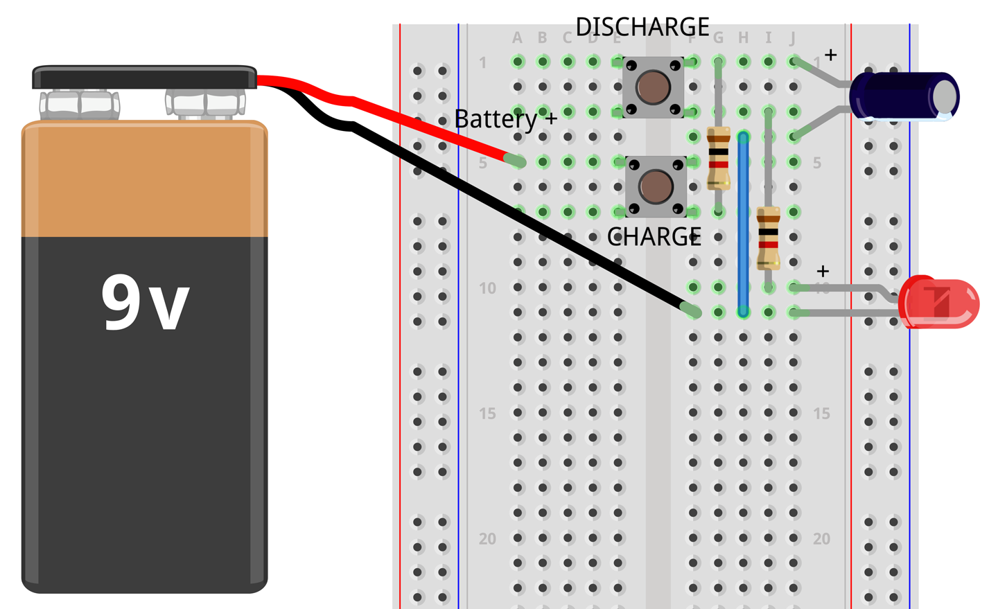
Figure 3-4. Breadboard Layout for Capacitor Experimentation
Press the button labeled CHARGE for a second or two to charge the capacitor then release the button and press the DISCHARGE button. The LED should glow brightly for a second or so and then dim until it extinguishes after a second or so.
If you were to monitor the voltage across the capacitor while it was first being charged and then discharged, you would see something similar to Figure 3-5.
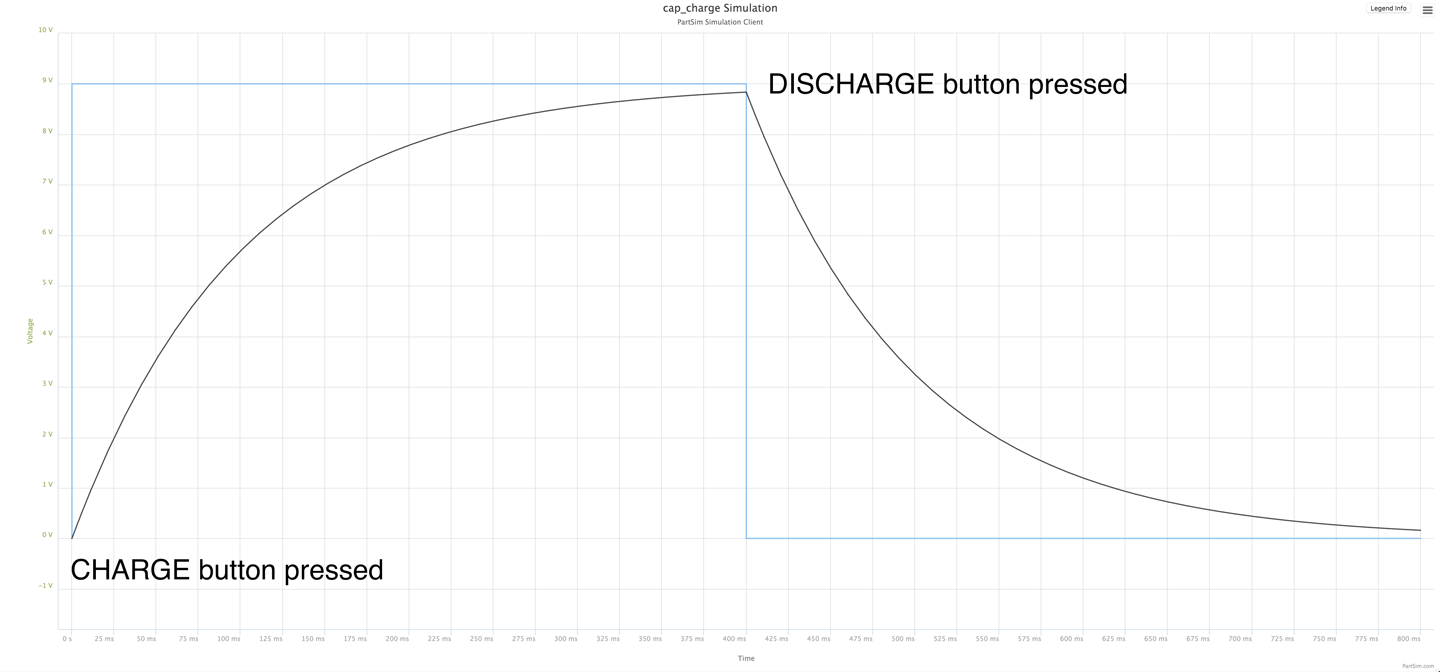
Figure 3-5. Charging and Discharging a Capacitor
In Figure 3-5 the square-shaped waveform is the voltage applied to the capacitor through a 1kΩ resistor. For the first 400ms this is 9V. But as you can see the voltage across the capacitor does not increase linearly, but rather increases faster at first and then gradually tails off as the voltage across the capacitor gets closer to the battery voltage.
Similarly, when the capacitor discharges, the voltage decreases sharply at first and then starts to tail off.
So, if a capacitor stores electrical energy, you may be wondering how this differs from a rechargeable battery. Well, in fact a special type of very high capacitance capacitor called a supercapacitor is sometimes used in place of a rechargeable battery for applications that require a very rapid storage and release of energy. The differences between a capacitor and a battery include:
- A rechargeable battery uses a chemical reaction to generate electricity’ a capacitor stores charge directly.
- A rechargeable battery must be charged and discharged over a period of minutes or hours. A capacitor can charge and discharge in fractions of a second.
- The voltage across a capacitor falls off sharply as it starts to discharge, whereas the voltage across a battery stays relatively constant until most of the energy is used.
- Per unit size, a battery can store around ten times as much energy as the best supercapacitor.
See Also
For information on using a solderless breadboard, see Recipe 20.1.
The voltage curves of Figure 3-5 were created using a circuit simulator (Recipe 21.11). You can experiment with this simulation online using PartSim at http://bit.ly/2mrtrhs.
3.2 Identify Types of Capacitors
Solution
Unless your application needs capacitors with special features, the following rule of thumb applies.
In most cases, for capacitors between 1pF and 1nF use a disc capacitor (Figure 3-6a). For capacitors between 1nF and 1µF use a multilayer ceramic capacitor (MLC; Figure 3-6b) and for capacitors above 1µF use an aluminum electrolytic capacitor (Figure 3-6c). The rightmost capacitor is a tantulum electrolytic capacitor.
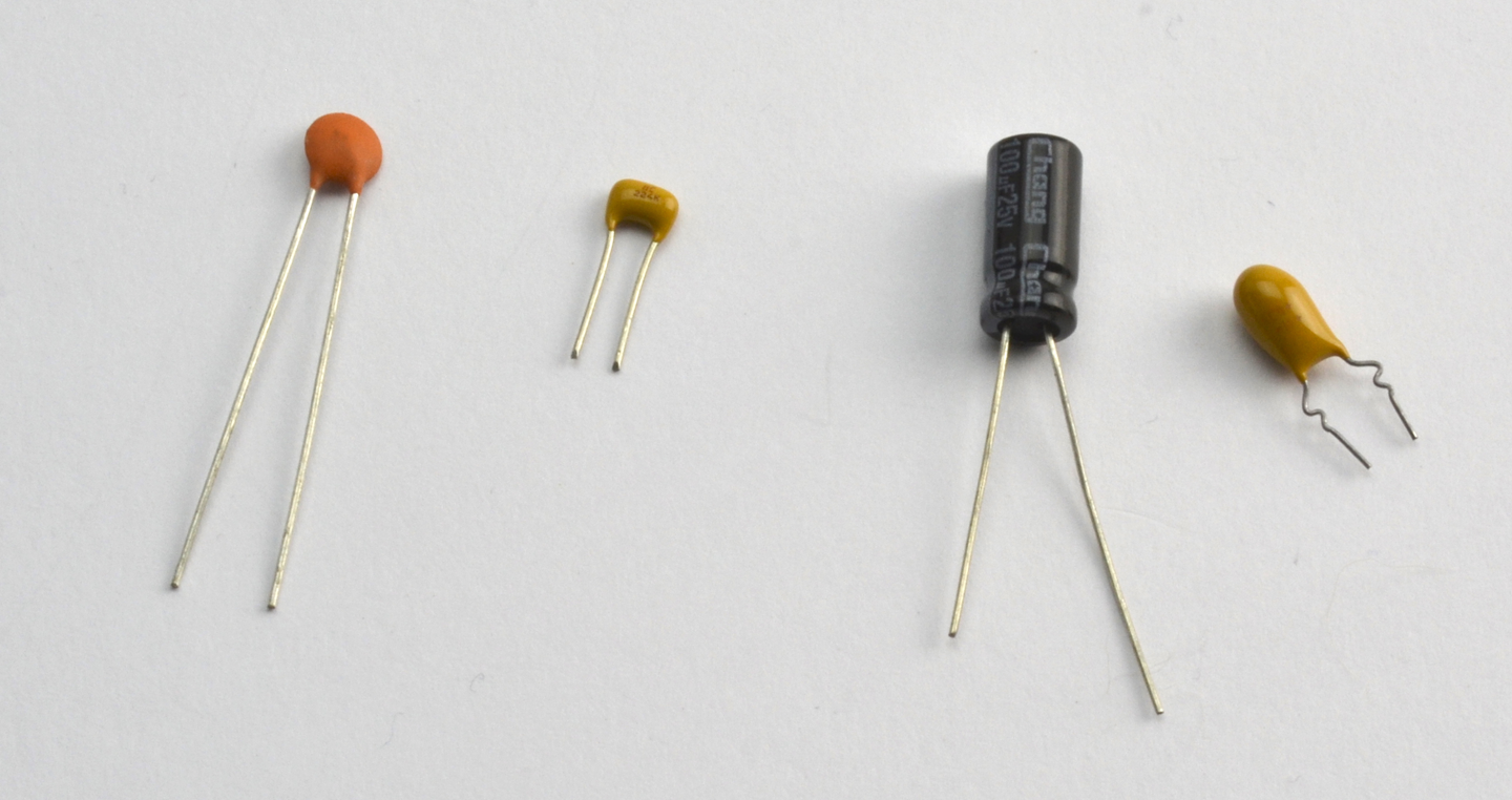
Figure 3-6. Capacitor Types: (a) Disc Ceramic, (b) MLC, (c) Aluminum Electrolytic, and (d) Tantulum
Discussion
Although disc ceramic, MLC, and aluminum electrolytic capacitors are the most commonly used types of capacitor, there are other types:
- Glass and mica capacitors offer a wide temperature range, but are expensive compared to other types of capacitor.
- Tantulum electrolytic capacitors are polarized capacitors that have values around the overlap between the ranges of MLC and electrolytic capacitors. They are small, but relatively expensive and available in values up to a few tens of µF. They suffer from the disadvantage that when they fail, they generally fail in such a way that the terminals of the capacitor become connected to each other, often with fairly explosive consequences. Improvements in MLC capacitors have led to upper values of capacitance of hundreds of µF making tantulum capacitors something of a rarity.
Capacitors are less reliable than resistors. Exceed the voltage rating and you are likely to damage the insulating layer. Electrolytic capacitors use an electrolyte contained in an aluminum can that creates a very thin layer of oxide as the insulator. These are especially prone to failure due to overvoltage, or overtemperature, or just age. If vintage HiFi equipment fails, it is usually the large electrolytic capacitors in the power supplies that are the cause of the failure. In addition, if an electrolytic capacitor does fail then it can spray out the electrolyte in a somewhat messy manner.
Voltage rating
In addition to the actual capacitance of a capacitor, there are a number of other factors to consider when selecting a device. Of critical importance is the voltage rating. Unless you are creating something that uses high voltages, this is not usually a problem with smaller value capacitors, as they are generally rated at least 50V. However, as soon as you get into the range of electrolytics then you will be in a trade-off between capacitor size and voltage. Electrolytic capacitors are commonly available in voltage ratings of 6.3V, 10V, 25V, 30V, 40V, 50V, 63V, 100V, 160V, 200V, 250V, 400V, and 450V. It is unusual to find electrolytic capacitors with a higher voltage rating than 500V.
ESR (equivalent series resistance)
The temperature rating becomes important when the capacitors are being rapidly charged and discharged, as a capacitor will always have an internal resistance called its equivalent series resistance (ESR) that causes heating during charging and discharging.
Small-value MLC capacitors generally have a very low ESR of little more than the resistance caused by their leads. This allows them to charge and discharge extremely quickly. A high-value electrolytic capacitor might have an ESR of a few hundred mΩ. This both limits the speed at which the capacitors can charge and discharge and causes a heating effect.
See Also
For the use of electrolytic capacitors to smooth out voltage ripple from power supplies, see Recipe 7.4.
3.3 Read Capacitor Packages
Solution
Small, low-value SMD capacitors are generally unmarked, and so you should label them as soon as you buy them.
Electrolytic capacitors usually have their capacitance value and voltage rating printed on the package. Polarized through-hole electrolytic capacitors are also usually supplied with the positive lead longer than the negative lead and the negative lead marked with a minus sign or a diamond symbol.
Most other capacitors use a numbering system similar to that of SMD resistors. The value is usually three digits and a letter. The first two digits are the base value and the third digit is the number of zeros to follow. The base value being the value in pF (pico Farad; see Appendix D).
For example, a 100pF capacitor would have the three digits 101 (a 1, a 0, followed by one further 0). A 100nF capacitor would be marked 104 (a 1, a 0, followed by four further 0s); that is, 100,000 pF or 100nF.
The letter after the digits indicates the tolerance (J, K, or M for ±5%, ±10%, and ±20%, respectively).
See Also
To read resistor color codes, see Recipe 2.1.
3.4 Connect Capacitors in Parallel
Solution
Looking at Figure 3-7, you can see two capacitors in parallel double up on the surface area of the conductive plates and therefore may correctly assume that the overall capacitance is the sum of the two capacitances.
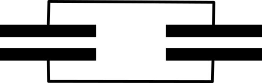
Figure 3-7. Two Capacitors in Parallel
Discussion
It is actually quite common to place a number of capacitors in parallel to increase the overall capacitance. It is especially common when smoothing a high-power transformer-based power supply for, say, an audio amplifier where it is important to remove as much ripple from the power supply as possible (see Recipe 7.2).
In such systems it is common to use a number of different capacitors of different types and values in parallel to minimize the effects of ESR (see Recipe 3.2).
See Also
For capacitors in series, see Recipe 3.5.
3.5 Connect Capacitors in Series
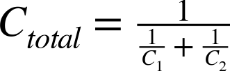
Discussion
It is unusual to connect capacitors in series. Occasionally, this will be done as part of a more complex circuit such as in Recipe 7.12.
See Also
For capacitors in parallel, see Recipe 3.4.
3.6 Store Huge Amounts of Energy
Solution
Supercapacitors are low-voltage capacitors that have extremely high capacitances. They are primarily used as energy-storage devices in situations that would otherwise use rechargeable batteries.
They can have values up into the hundreds of F (Farads). Note that the top of the capacitance range for an aluminum electrolytic is around 0.22F.
Discussion
Low (comparatively) value supercapacitors of perhaps a few F are sometimes used as alternatives to rechargeable batteries or long-life lithium batteries to power ICs in standby mode to retain memory in static RAM that would otherwise be lost, or to power real-time clock (RTC) chips so a device using an RTC IC will keep the time if it’s powered off for a while.
Extremely high-value supercapacitors are available that offer an alternative to rechargeable batteries for larger capacity energy storage.
Supercapacitors with values of 500F or more can be bought for just a few dollars. The maximum voltage for a supercapacitor is 2.7V so, for higher voltage use, the capacitors can be placed in series with special protection circuitry to ensure the 2.7V limit is not exceeded as the bank of capacitors are charged.
Supercapacitors generally look like standard aluminum electrolytic capacitors. At present, their energy storage is still quite a long way from that of rechargeable batteries and because they are capacitors, the voltage decreases much more quickly than when discharging a battery.
See Also
See Recipe 3.7 to calculate the energy stored in super capacitors and normal capacitors.
3.7 Calculate the Energy Stored in a Capacitor
Solution
The energy stored in a capacitor in J is calculated as:
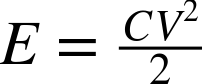
Discussion
Taking a medium-sized electrolytic of 470µF at 35V the energy stored would be:
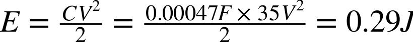
which is not very much energy. Since the energy storage is proportional to the square of the voltage, the results for a capacitor of the same value but at 200V are much more impressive:
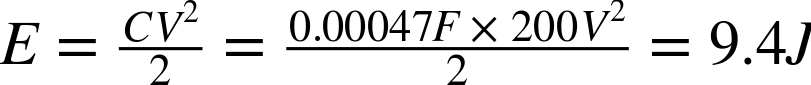
For a 500F 2.7V supercapacitor, the results are even more impressive:

By way of comparison, a single 1.5V AA battery of 2000mAH stores around:

See Also
For information on rechargeable batteries, see Recipe 8.3.
3.8 Modify and Moderate Current Flow
Solution
An inductor is, at its simplest, just a coil of wire. At DC, it behaves just like any length of wire and will have some resistance, but when AC flows through it, it starts to do something interesting.
A change in current in one direction in an inductor causes a change in voltage in the opposite direction. This effect is more marked the higher the frequency of the AC flowing through the inductor. The net result of this is that the higher the frequency of the AC, the more the inductor resists the flow of current. So as not to confuse this effect with ordinary resistance, it is called reactance but it still has units of Ω.
The reactance X of an inductor can be calculated by the formula:

Where f is the frequency of the AC (cycles per second) and L is the inductance of the inductor whose units are the Henry (H). This resistive effect does not generate heat like a resistor, but rather returns the energy to the circuit.
The inductance of an inductor will depend on the number of turns of wire as well as what the wire is wrapped around. So, very low-value inductors may be just a couple of turns of wire without any core (called air-core inductors). Higher value inductors will generally use an iron or more likely ferrite core. Ferrite is a magnetic ceramic material.
The current-carrying capability of an inductor generally depends on the thickness of the wire used in the coil.
Discussion
Inductors are used in switched mode power supplies (SMPS) where they are pulsed at a high frequency (see Recipe 7.8 and Recipe 7.9). They are also used extensively in radio-frequency electronics, where they are often combined with a capacitor to form a tuned circuit (see Chapter 19).
A type of inductor called a choke is designed to let DC pass while blocking the AC part of a signal. This prevents unwanted radio-frequency noise from infiltrating a circuit. You will often find a USB lead has a lump in it near one end. This is a ferrite choke, which is just a cylinder of ferrite material that encloses the cables and increases the inductance of the wire to a level where it can suppress high-frequency noise.
See Also
For more information on the use of inductors in SMPSs, see Recipe 7.8 and Recipe 7.9.
See Recipe 3.9 for more information on transformers.
3.9 Convert AC Voltages
Solution
A transformer is essentially two or more inductor coils wrapped onto a single core. Figure 3-8 shows the schematic diagram for a transformer that also gives a clue as to how it works.
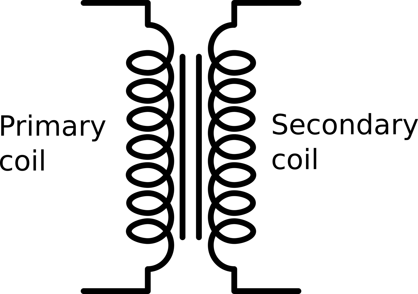
Figure 3-8. The Transformer
A transformer has primary coils and secondary coils. Figure 3-8 shows one of each. The primary coil is driven by AC, say the 110V from an AC outlet, and the secondary is connected to the load.
The voltage at the secondary is determined by the ratio of the number of turns on the primary to the number of turns on the secondary. Thus if the primary has 1000 turns and the secondary just 100, then the AC voltage will be reduced by a factor of 10.
Figure 3-9 shows a selection of transformers. As you can see they come in a wide range of sizes.
In Figure 3-9 there is a small high-frequency transformer on the left that was taken from a disposable flash camera where it was used to step up pulsed DC (almost AC) from a 1.5V battery to the 400V needed by a Xenon flash tube.
The type of transformer shown in the center is commonly used to step-down 110V AC to a low voltage, say 6V or 9V.
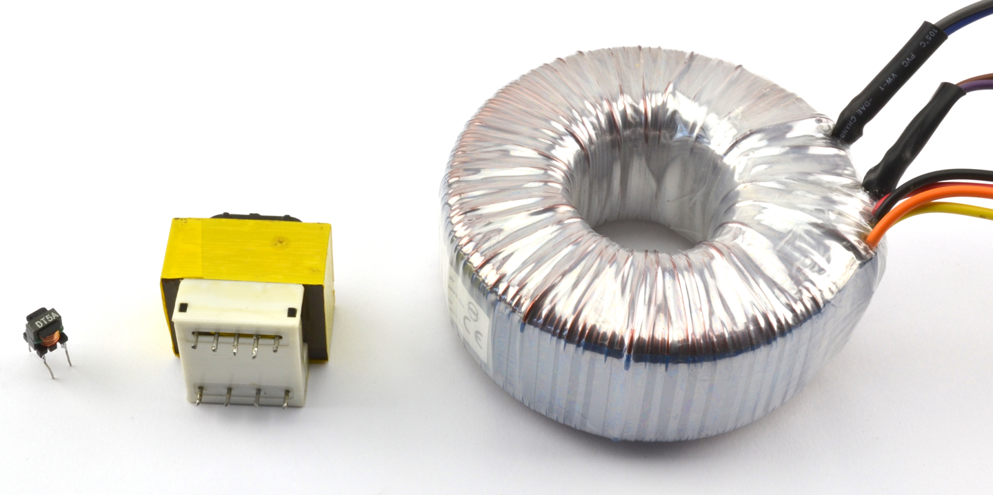
Figure 3-9. A Selection of Transformers
The transformer on the right is also designed to step-down AC outlet voltages to lower voltages. It is called a torroidal transformer and the primary and secondary coils are wrapped around a single torroidal former (donut shaped arrangement of iron layers), on top of each other. These transformers are often used in HiFi equipment where the noise found in most SMPSs is considered too high for high-end HiFi amplifiers.
Discussion
It used to be that if you wanted to power a low-voltage DC appliance such as a radio receiver from an AC outlet, then you would first use a transformer to drop the 100V AC at 60Hz to, say, 9V. You would then rectify and smooth the low-voltage AC into DC.
These days, an SMPS (see Recipe 7.8) is normally used as transformers are expensive and heavy items with iron and long lengths of copper-winding wire. However, transformers are still used in SMPS but operate at a very much higher frequency than 60Hz. Operating at a high frequency (often 100s of kHz) allows the transformers to be much smaller and lighter than low-frequency transformers while retaining good efficiency.
See Also
This video shows a torroidal transformer winding machine in action: https://youtu.be/82PpCzM2CUg.
Recipe 7.1 describes how to use a transformer to convert one AC voltage to another.