Table of Contents for
Electronics Cookbook
 Electronics Cookbook
Published by
O'Reilly Media, Inc., 2017
Electronics Cookbook
Published by
O'Reilly Media, Inc., 2017
- Cover
- nav
- Electronics Cookbook
- Electronics Cookbook
- Preface
- Theory
- Resistors
- Capacitors and Inductors
- Diodes
- Transistors and Integrated Circuits
- Switches and Relays
- Power Supplies
- Batteries
- Solar Power
- Arduino and Raspberry Pi
- Switching
- Sensors
- Motors
- LEDs and Displays
- Digital ICs
- Analog
- Operational Amplifiers
- Audio
- Radio Frequency
- Construction
- Tools
- Parts and Suppliers
- Arduino Pinouts
- Raspberry Pi Pinouts
- Units and Prefixes
- Index
- About the Author
- Colophon
Chapter 2. Resistors
2.0 Introduction
Resistors are used in almost every electronic circuit, come in a huge variety of shapes and sizes, and are available in a range of values that spans milliohms (thousandths of an ohm) to mega ohms (millions of ohms).
Ohm, the unit of resistance, is usually abbreviated as the Greek letter omega (Ω), although you will sometimes see the letter R used instead. For example, 100Ω and 100R both mean a resistor with a resistance of 100 ohms.
2.1 Read Resistor Packages
Solution
On a through-hole resistor (a resistor with leads) that has colored stripes on it, use the resistor color code.
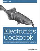
If your resistor has stripes in the same positions as Figure 2-1 then the three stripes together on the left determine the resistor’s value and the single stripe on the right determines the accuracy of the value.
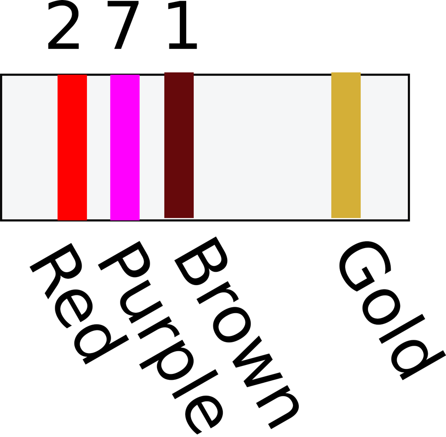
Figure 2-1. A Three-Stripe Resistor
Each color has a value as listed in Table 2-1.
|
Black |
0 |
|
Brown |
1 |
|
Red |
2 |
|
Orange |
3 |
|
Yellow |
4 |
|
Green |
5 |
|
Blue |
6 |
|
Violet |
7 |
|
Gray |
8 |
|
White |
9 |
|
Gold |
1/10 |
|
Silver |
1/100 |
For a three-stripe resistor such as this, the first two stripes determine the basic value (say 27 in Figure 2-1) and the third stripe determines the number of zeros to add to the end. In the example of Figure 2-1, the value of a resistor with stripes red, purple, and brown is 270Ω. I said before that this stripe indicates the number of zeros, but actually, to be more accurate, it is a multiplier. If it has a value of gold, then this means ⅒ of the value indicated by the first two stripes. So brown, black, and gold would indicate a 1Ω resistor.
The stripe on its own specifies the tolerance of the resistor. Silver (rare these days) indicates ±10%, gold ±5%, and brown ±1%.
If your resistor has stripes as shown in Figure 2-2 then the value of the resistor is specified with an extra digit of precision. In this case, the first three stripes determine the basic value (in the case of Figure 2-2, 270) and the final digit the number of zeros to add (in this case, 0). This resistor is also 270Ω.
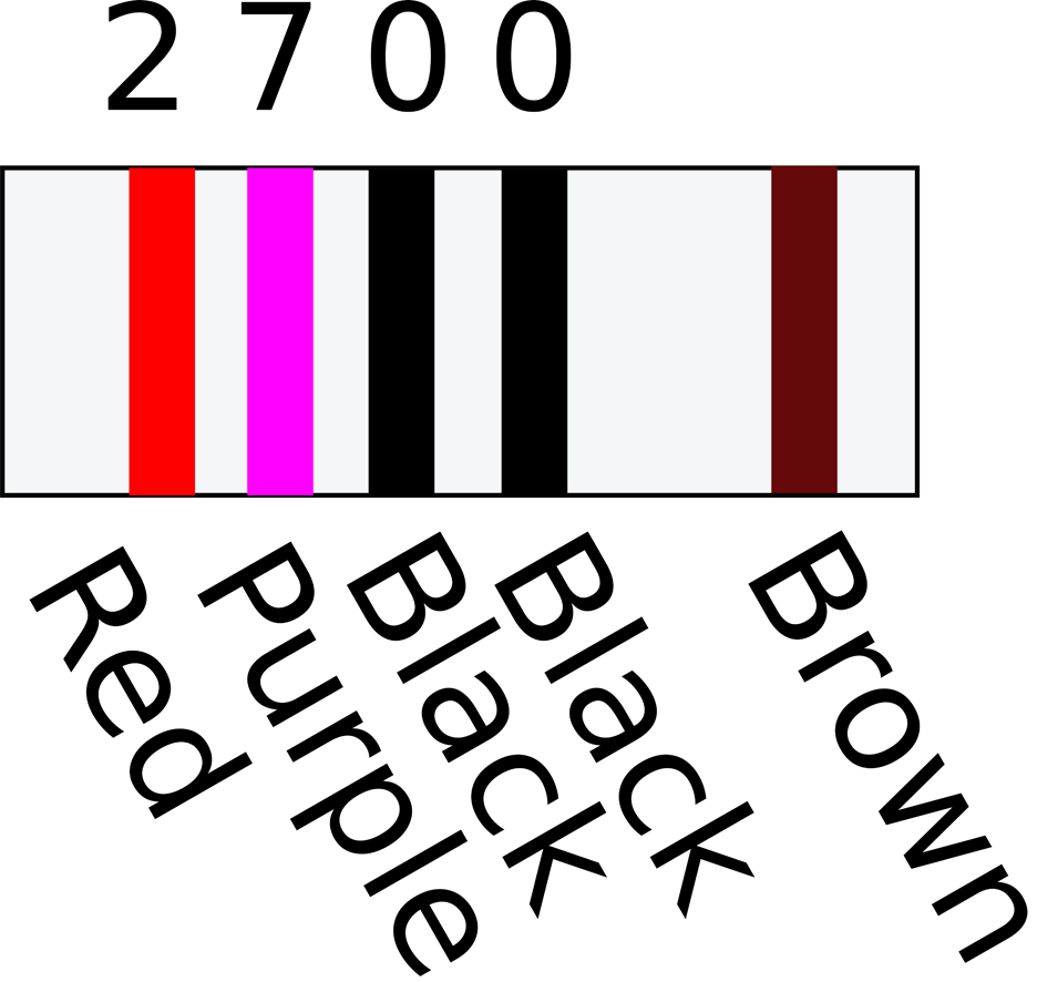
Figure 2-2. A Four-Stripe Resistor
For low-value resistors, gold is used as a multiplier of 0.1 and silver of 0.01. A 1Ω four-stripe resistor would have value stripes of brown, black, black, and silver (100 x 0.01).
See Also
Through-hole capacitors also have value labels similar to SMT resistors (see Recipe 3.3).
2.2 Find Standard Resistor Values
Discussion
The ±1% E96 series includes all the base values of the E24 series, but has four times as many values. However, it is very rare to need such precise values of resistor.
If your resistor is to limit current to some other component that might be damaged, perhaps limiting the power to an LED (Recipe 4.4) or into the base of a bipolar transistor (Recipe 5.1), then pick the next largest value of resistor from the E24 series.
For example, if your calculations tell you that the resistor should be a 239Ω resistor, then pick a 240Ω resistor from the E24 series.
In reality, you may decide to limit yourself even further to avoid having to gradually collect every conceivable value of resistor, especially as they are often sold in packs of 100. I generally keep the following resistor values in stock: 10Ω, 100Ω, 270Ω, 470Ω, 1k, 3.3k, 4.7k, 10k, 100k, and 1M.
See Also
For full details on all of the resistor series available, see http://www.logwell.com/tech/components/resistor_values.html.
2.3 Select a Variable Resistor
Solution
A variable resistor, a.k.a. a pot or potentiometer, is made from a resistive track and a slider that varies its position along the track. By varying the position of the slider you can vary the resistance between the slider and either of the terminals at the ends of the track. The most common pots are rotary like the one shown in Figure 2-3.
Figure 2-3. A Rotary Pot
Discussion
Pots come in a large variety of shapes and sizes. Figure 2-4 shows a selection of pots.
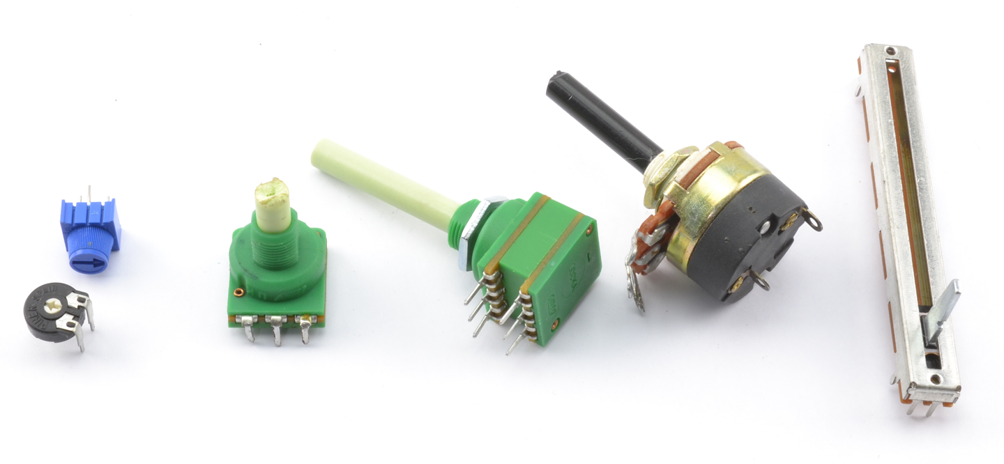
Figure 2-4. Potentiometers
The two pots on the left of Figure 2-4 are called trimmers or trimpots. These devices are designed to be turned using a screwdriver or by twiddling the tiny knob between the thumb and forefinger.
The next pot is a pretty standard device with a threaded barrel that allows the pot to be fixed into a hole. The shaft can be cut to the length required before fixing a knob to it.
There is a dual-gang pot in the middle of Figure 2-4. This is actually two pots with a common shaft and is often employed in stereo volume controls. After that is a similar looking device that combines a pot with an on/off switch. Finally, on the right is a sliding type of pot, the kind that you might find on a mixing desk.
Pots are available with two types of tracks. Linear tracks have a close to linear resistance across the whole range of the pot. So, at the half-way point the resistance will be half of the full range.
Pots with a logarithmic track increase in resistance as a function of the log of the slider position rather than in proportion to the position. This makes them more suitable to volume controls as human perception of loudness is logarithmic. Unless you are making a volume control for an audio amplifier, you probably want a linear pot.
See Also
To connect a pot to an Arduino or Raspberry Pi, see Recipe 12.9.
A potentiometer lends itself to being a variable voltage divider (see Recipe 2.6).
2.4 Combine Resistors in Series
Solution
The overall resistance of a number of resistors in series is just the sum of the separate resistances.
Discussion
Figure 2-5 shows two resistors in series. The current flows through one resistor and then the second. As a pair, the resistors will be equivalent to a single resistor of 200Ω.
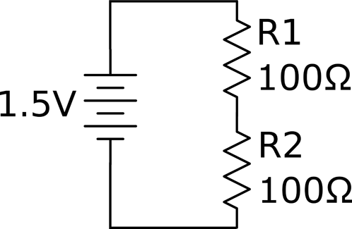
Figure 2-5. Resistors in Series
The heating power of each resistor will be 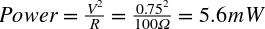 .
.
If you used a single resistor of 200Ω then the power would be:

So, by using two resistors, you can double the power.
You may be wondering why you would ever want to use two resistors in series when you could just use one. Power dissipation may be one reason, if you cannot find resistors of sufficient power.
But there are other situations, such as the one shown in Figure 2-6, where you use a variable resistor (pot) with a fixed resistor to make sure that the combination’s resistance does not fall below the value of the fixed resistor.
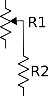
Figure 2-6. A Pot and Fixed Resistor
See Also
Resistors in series are often used to form a voltage divider (see Recipe 2.6).
2.5 Combine Resistors in Parallel
Solution
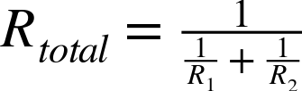
The combined resistance of a number of resistors in parallel is the inverse of the sum of the inverses of the resistors. That is, if there are two resistors R1 and R2 in parallel, then the overall resistance is given by:
Discussion
In the example shown in Figure 2-7 with two 100Ω resistors in parallel, the arrangement is equivalent to a single resistor of:
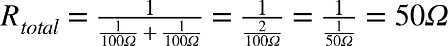
Intuitively, this makes perfect sense, because there are now two equally resistive paths through the resistors instead of one as would be the case with a single resistor.
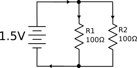
Figure 2-7. Resistors in Parallel
In Figure 2-7 a single 50Ω resistor is equivalent to the two 100Ω resistors in parallel, but what implications does this have for the power ratings of the two resistors?
Intuitively, you would expect the total power dissipation of two 100Ω resistors to be the same as the two 50Ω resistors, but just to be sure let’s do the math.
For each 100Ω resistor, the power will be:

So the total for the two resistors will be 45mW, allowing you to use lower power and more common resistors.
Just as you’d expect, performing the calculation for the single 50Ω resistor you get:

See Also
See Recipe 2.4 for resistors in series.
2.6 Reduce a Voltage to a Measurable Level
Solution
Use two resistors in series as a voltage divider (also called potential divider). The word “potential” indicates the voltage has the potential to do work and make current flow.
Figure 2-8 shows a pair of resistors being used as a voltage divider.
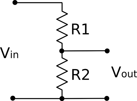
Figure 2-8. A Voltage Divider
The output voltage (Vout) will be a fraction of the input voltage (Vin) according to the formula:
For example, if R1 is 470Ω, R2 is 270Ω, and Vin is 5V:

Discussion
Note that if R1 and R2 are equal then the voltage is divided by 2.
A pot naturally forms a potential divider as you can think of it as two resistors in series whose overall resistance adds up to the same value, but the proportion of the resistance of R1 to R2 varies as you turn the knob. This is just how a pot is used in a volume control.
It may be tempting to think of a voltage divider as useful for reducing voltages in power supplies. However, this is not the case, because as soon as you try to use the output of the voltage divider to power something (a load), it is as if another resistor is being put in parallel with R2. This effectively reduces the resistance of the bottom half of the voltage divider and therefore also reduces the output voltage. This will only work if R1 and R2 are much lower than the resistance of the load. This makes them great for reducing signal levels, but of no use for high-power circuits.
See Also
See Chapter 7 for various techniques for reducing voltages in power supplies.
For level shifting with a voltage divider, see Recipe 10.17.
2.7 Choose a Resistor that Won’t Burn Out
Solution
Calculate the power (Recipe 1.6) your resistor will be converting into heat and pick a resistor with a power rating comfortably greater than this value.
For example, if you have a 10Ω resistor connected directly to the terminals of a 1.5V battery, then the power that the resistor converts to heat can be calculated as:
This means that a standard ¼W resistor will be OK, but you may wish to take the next step up to ½W.
Discussion
The most common power rating of resistor used by hobbyists is the ¼W (250mW) resistor. These resistors are not so tiny that they are hard to handle or the leads too thin to make good contact in breadboard (Recipe 20.1) yet they are capable of handling enough power for most uses, such as limiting current to LEDs (Recipe 14.1) or used as voltage dividers for low current (Recipe 2.6).
Other common power ratings for through-hole resistors with leads are ½W, 1W, 2W, 5W, 10W, and even higher power resistors.
Figure 2-9 shows a selection of resistors of different power ratings.
When it comes to the tiny surface-mount “chip resistors” that are surface mounted onto circuit boards, power ratings start much lower.
See Also
To understand power, see Recipe 1.6.
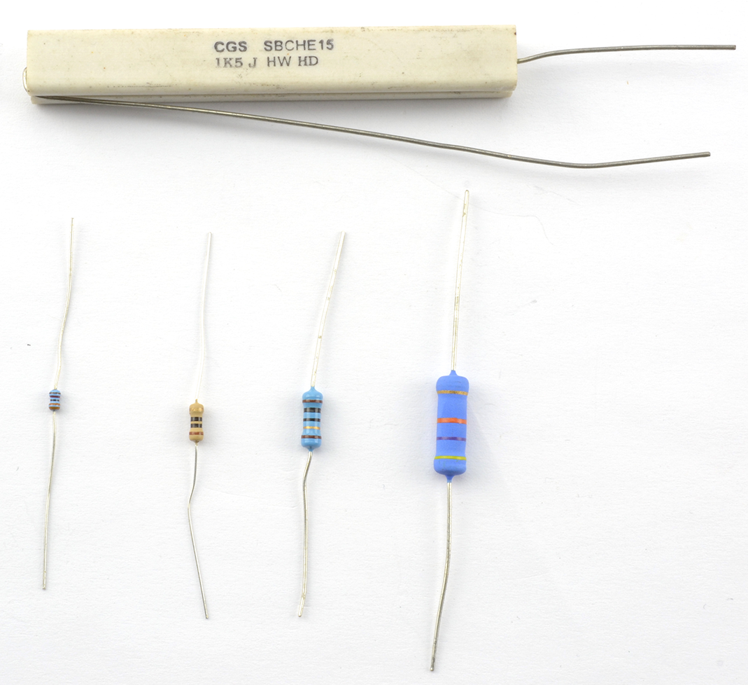
Figure 2-9. Resistors from Left to Right: 0.125W, 0.25W, 0.5W, 1W, and 7W at the Top
2.8 Measure Light Levels
Solution
Use a photoresistor.
A photoresistor (Figure 2-10) is a resistor in a clear plastic package whose resistance varies depending on the amount of light falling on it. The more brightly the photoresistor is illuminated, the lower the resistance.
A typical photoresistor might have a resistance in direct sunlight of 1kΩ increasing to several MΩ in total darkness.
Discussion
Photoresistors are often used in a voltage-divider arrangement (Recipe 2.6) with a fixed-value resistor to convert the resistance of the photoresistor into a voltage that can then be used with a microcontroller (Recipe 12.6) or comparator (Recipe 17.10).
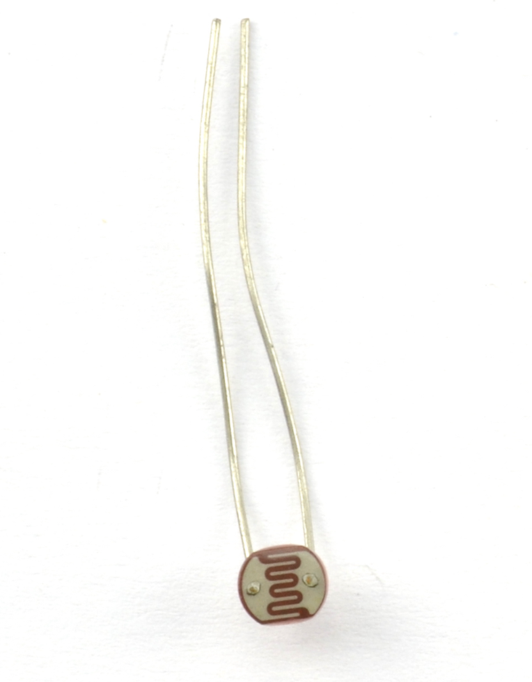
Figure 2-10. A Photoresistor
See Also
You will find more details on using a photoresistor in Recipe 12.6.
2.9 Measure Temperature
Solution
One method is to use a thermistor. Other ways can be found in Recipe 12.10 and Recipe 12.11.
All resistors are slightly sensitive to changes in temperature. However, thermistors (Figure 2-11) are resistors whose resistance is very sensitive to changes in temperature. As with photoresistors (Recipe 2.8), they are often used in a voltage divider (Recipe 2.6) to convert the resistance to a voltage reading that is more convenient.
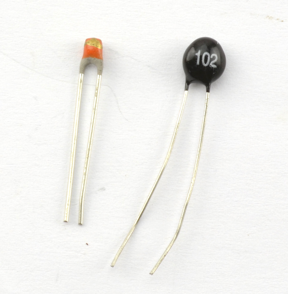
Figure 2-11. Two Thermistors
Discussion
There are two types of thermistors. NTC (negative temperature coefficient) thermistors are the more common type and their resistance decreases as the temperature increases. PTC (positive temperature coefficient) thermistors have a resistance that increases as the temperature increases.
In addition to being used to measure temperature (see Recipe 12.7) PTC thermistors are also used to limit current. As the current through the thermistor increases, the resistor heats up and thus its resistance increases, reducing the current.
See Also
For practical circuits that use a thermistor to measure temperature, see Recipe 12.7 and Recipe 12.8.
2.10 Choose the Right Wires
Solution
Wires all have resistance. A thick copper wire will have a much lower resistance than the same length of a much thinner wire. As someone once said, “the great thing about standards are that there are always lots to choose from.” Nowhere is this more true than for wire thicknesses or gauges. One of the most common standards is AWG (American Wire Gauge) mostly used in the US, and the SWG (Standard Wire Gauge) mostly used in the UK and most logically just the diameter of the wire in mm.
Nearly all wiring used in electronics is made of copper. If you strip the insulation off a wire and it looks silver-colored, then it’s probably still copper, but copper that has been “tinned” to stop it from oxidizing and make it easier to solder.
Table 2-2 shows some commonly used wire gauges along with their resistances in Ω per foot and meter for copper wiring.
| AWG | Diameter (mm) | mΩ/m | mΩ/foot | Max. Current (A) | Notes |
|---|---|---|---|---|---|
| 30 | 0.255 | 339 | 103 | 0.14 | |
| 28 | 0.376 | 213 | 64.9 | 0.27 | |
| 24 | 0.559 | 84.2 | 25.7 | 0.58 | Solid-core hookup wire |
| 19 | 0.95 | 26.4 | 8.05 | 1.8 | General-purpose multicore wire |
| 15 | 1.8 | 10.4 | 3.18 | 4.7 | Thick multicore wire |
The larger the AWG number the thicker the wire. Wires thinner than 24AWG are most likely to be thin enameled wire designed for winding transformers and indictors, like the wire shown in Figure 2-12.
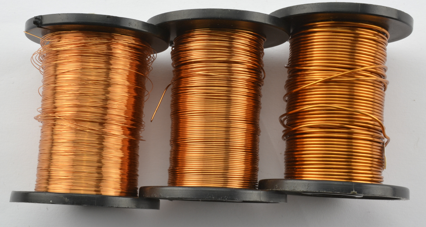
Figure 2-12. Enamel-Insulated Wire for Winding Inductors 30-22 AWG
Solid-core wire is made of a single strand of copper insulated in plastic (Figure 2-13). It is useful with solderless breadboards (Recipe 20.1) but should not be used in situations where it is likely to be flexed as it will break through metal fatigue if bent back and forth. I always have this wire in at least three colors so that I can use black for negative, red for positive, and other colors for nonpower connections.
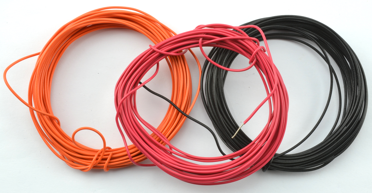
Figure 2-13. Single-core Hookup Wire (24 AWG)
For general-purpose wire where some movement is likely, use multicore wire made up of a number of strands of wire twisted about each other and encased in plastic insulation. Again, it’s useful to have a selection of colors.
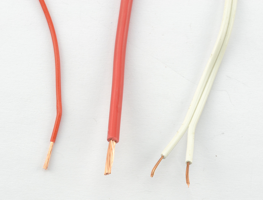
Figure 2-14. 19 and 15 AWG Multicore Wire with Twin “Bell-wire”
Discussion
The currents listed in Table 2-2 are only suggestions. The actual current that each gauge of wire can carry without getting too hot depends on many factors, including how well ventilated the project’s case is and whether the wires are all grouped together with a whole load of other wires all getting warm. So treat Table 2-2 as a guide.
When you buy wire, the maximum temperature of the insulation will usually be specified. This is not just because of internal heating of the wire but also for situations where the insulation is to be used in hot environments such as ovens or furnaces.
If you are looking for wires to carry high voltages then you will need a good insulation layer. Again, wires will normally have a breakdown voltage specified for the insulation.
See Also
For a table comparing wire gauges, see http://bit.ly/2lOyPIh.
For the current-handling capabilities of wire by gauge, see http://bit.ly/2mbgZS8.