Table of Contents for
Web Mapping Illustrated
 Web Mapping Illustrated
Published by
O'Reilly Media, Inc., 2005
Web Mapping Illustrated
Published by
O'Reilly Media, Inc., 2005
- Web Mapping Illustrated
- Cover
- Web Mapping Illustrated
- A Note Regarding Supplemental Files
- Foreword
- Preface
- Youthful Exploration
- The Tools in This Book
- What This Book Covers
- Organization of This Book
- Conventions Used in This Book
- Safari Enabled
- Comments and Questions
- Acknowledgments
- 1. Introduction to Digital Mapping
- 1.1. The Power of Digital Maps
- 1.2. The Difficulties of Making Maps
- 1.3. Different Kinds of Web Mapping
- 2. Digital Mapping Tasks and Tools
- 2.1. Common Mapping Tasks
- 2.2. Common Pitfalls, Deadends, and Irritations
- 2.3. Identifying the Types of Tasks for a Project
- 3. Converting and Viewing Maps
- 3.1. Raster and Vector
- 3.2. OpenEV
- 3.3. MapServer
- 3.4. Geospatial Data Abstraction Library (GDAL)
- 3.5. OGR Simple Features Library
- 3.6. PostGIS
- 3.7. Summary of Applications
- 4. Installing MapServer
- 4.1. How MapServer Applications Operate
- 4.2. Walkthrough of the Main Components
- 4.3. Installing MapServer
- 4.4. Getting Help
- 5. Acquiring Map Data
- 5.1. Appraising Your Data Needs
- 5.2. Acquiring the Data You Need
- 6. Analyzing Map Data
- 6.1. Downloading the Demonstration Data
- 6.2. Installing Data Management Tools: GDAL and FWTools
- 6.3. Examining Data Content
- 6.4. Summarizing Information Using Other Tools
- 7. Converting Map Data
- 7.1. Converting Map Data
- 7.2. Converting Vector Data
- 7.3. Converting Raster Data to Other Formats
- 8. Visualizing Mapping Data in a Desktop Program
- 8.1. Visualization and Mapping Programs
- 8.2. Using OpenEV
- 8.3. OpenEV Basics
- 9. Create and Edit Personal Map Data
- 9.1. Planning Your Map
- 9.2. Preprocessing Data Examples
- 10. Creating Static Maps
- 10.1. MapServer Utilities
- 10.2. Sample Uses of the Command-Line Utilities
- 10.3. Setting Output Image Formats
- 11. Publishing Interactive Maps on the Web
- 11.1. Preparing and Testing MapServer
- 11.2. Create a Custom Application for a Particular Area
- 11.3. Continuing Education
- 12. Accessing Maps Through Web Services
- 12.1. Web Services for Mapping
- 12.2. What Do Web Services for Mapping Do?
- 12.3. Using MapServer with Web Services
- 12.4. Reference Map Files
- 13. Managing a Spatial Database
- 13.1. Introducing PostGIS
- 13.2. What Is a Spatial Database?
- 13.3. Downloading PostGIS Install Packages and Binaries
- 13.4. Compiling from Source Code
- 13.5. Steps for Setting Up PostGIS
- 13.6. Creating a Spatial Database
- 13.7. Load Data into the Database
- 13.8. Spatial Data Queries
- 13.9. Accessing Spatial Data from PostGIS in Other Applications
- 14. Custom Programming with MapServer’s MapScript
- 14.1. Introducing MapScript
- 14.2. Getting MapScript
- 14.3. MapScript Objects
- 14.4. MapScript Examples
- 14.5. Other Resources
- 14.6. Parallel MapScript Translations
- A. A Brief Introduction to Map Projections
- A.1. The Third Spheroid from the Sun
- A.2. Using Map Projections with MapServer
- A.3. Map Projection Examples
- A.4. Using Projections with Other Applications
- A.5. References
- B. MapServer Reference Guide for Vector Data Access
- B.1. Vector Data
- B.2. Data Format Guide
- ESRI Shapefiles (SHP)
- PostGIS/PostgreSQL Database
- MapInfo Files (TAB/MID/MIF)
- Oracle Spatial Database
- Web Feature Service (WFS)
- Geography Markup Language Files (GML)
- VirtualSpatialData (ODBC/OVF)
- TIGER/Line Files
- ESRI ArcInfo Coverage Files
- ESRI ArcSDE Database (SDE)
- Microstation Design Files (DGN)
- IHO S-57 Files
- Spatial Data Transfer Standard Files (SDTS)
- Inline MapServer Features
- National Transfer Format Files (NTF)
- About the Author
- Colophon
- Copyright
Create a Custom Application for a Particular Area
MapServer has many different settings you will want to learn more about as you develop your skills. A very small, core subset of options are used in the examples in this chapter. For a complete listing of map file settings, see the map file reference document at http://mapserver.gis.umn.edu/doc/mapfile-reference.html.
Also note that there are several MapServer CGI variables used in this chapter. For more information see the current MapServer CGI reference document at http://mapserver.gis.umn.edu/doc/cgi-reference.html.
Changing the Initial Extent of the Map
In Chapter 10
you learned how to change the extents of the map when using the
shp2img command-line utility. With
an interactive map the extents can be changed by zooming in, just like
the test example with the global map application. The initial map
shown by that application covers the whole world. If you are
interested only in a map covering a certain area, you will want to
change the initial extent of the map to suit your area of
interest.
You will continue to build on the previous examples in this
chapter, including the global.map file. The
EXTENT line in the map file
specifies what the initial extent of the map will be when MapServer
starts up. This was set to:
EXTENT -180 -90 180 90
which covers the whole world. Now you will set this to zoom in
to a new area, to make a map of Canada. You will do so by continuing
to use the countries_simpl.shp shapefile, and
also use the ogr2ogr and ogrinfo tools to
assess what extent you need. Please see the procedures for using
ogr2ogr and ogrinfo in Chapter 10. Example 10-5 shows the same
methodology for determining the extent of Bulgaria.
These command-line programs aren’t part of MapServer. They are
part of the GDAL/OGR package described in Chapter 3. The ogr2ogr utility extracts the shapes of
Canada and saves them in to a new shapefile. ogrinfo is then run to see what the
coordinate extents of Canada are.
Tip
The OGR utilities are available as part of the FWTools package. You can download it from http://fwtools.maptools.org.
The new shapefile is used only as a temporary means of determining the coordinates of the area of interest. These coordinates are then set in global.map so that MapServer focuses on Canada.
The extent of Canada, as returned from ogrinfo, is:
Extent: (-141.000000, 41.675980) - (-52.636291, 83.110458)
You can put this extent into the global.map file and see how things look. Simply copy/paste this text right into the map file and then clean it up, removing brackets and commas. Example 11-4 shows how the first few lines of the changed application look.
MAP
  SIZE 600 300
  EXTENT -141 42 -52 83
...
    CLASS
      NAME 'Canada'
      EXPRESSION 'Canada'
      OUTLINECOLOR 100 100 100
      COLOR 255 255 150
    END
...
In this example, exact coordinates aren’t required. You can
round them off or drop the decimals. Note the changes to the LAYER object. The class that highlighted
Bulgaria now highlights Canada instead. The LABEL object has been removed from the
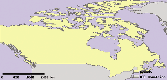
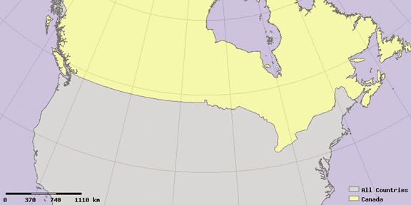
CLASS object. Figure 11-4 shows the initial
map produced by using these new extent settings.
The extents of this map are so tight that it is hard to really get the context of the map. It is zoomed in so tightly to Canada that it’s difficult to see any of the neighboring countries.
Warning
MapServer has been very accurate about displaying the map according to the requested extent. That’s a good thing. Some mapping programs always add on an extra bit of space around the feature you have asked to display. While this is usually helpful when creating a quick graphic, it isn’t always helpful when you are trying to be accurate.
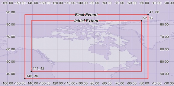
To make the map look a little nicer, increase the extent settings by five degrees. Here are the the initial and final extents:
- Initial extents
EXTENT -141 42 -52 83- Final extents
EXTENT -146 37 -47
              88
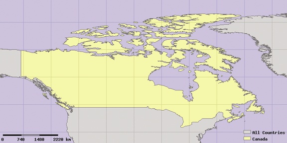
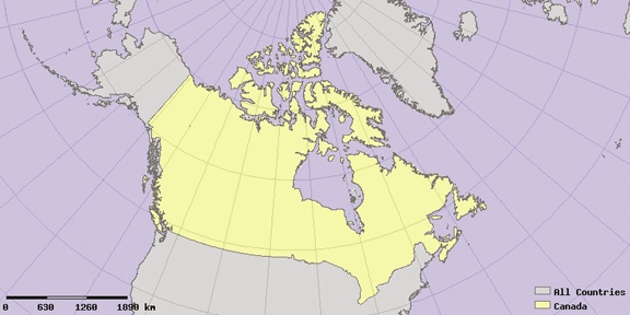
The values of the new extent aren’t just all increased or decreased. The minimum values (the first two numbers) are decreased because I want more of the south and west of the map to be shown. The maximum values (the last two numbers) are increased to show more of the north and east parts of the map. Increased here means made more positive, not just increasing the absolute value. This holds true for the western hemisphere north of the equator, and when using latitudes and longitudes. Figure 11-5 shows where the extents are on a map. Figure 11-6 shows the resulting map that uses the final extent.
Changing the Map Projection
If no PROJECTION
objects are set for the map or the layers, MapServer assumes they are
all in the same coordinate system. Therefore, no reprojection is
required. For data in decimal degrees, MapServer uses a default map
projection (a.k.a. Plate Caree). This default projection isn’t the
best way to display this map because it distorts several properties of
the map. A large part of Canada is in the polar region, which this
projection specifically distorts.
Tip
Some examples of changing projections are discussed here. Appendix A discusses map projections in more depth.
Setting the map and layer projections
The first thing you must know is that each layer can have a projection set for it, and the overall map can have a projection as well. If the data in the layers is a different projection than what you want displayed, MapServer will have to reproject the source data. You have to set each layer with a projection so that MapServer knows how to reproject the data into the desired output projection for the map.
The first PROJECTION object
in the map file is often called the map file’s global projection
setting. It is part of the MAP
object. The other place projections are set is within the LAYER object. This tells MapServer what
projection the map data within the data source of that layer uses.
If it is different than the MAP
projection, MapServer will reproject the source data into the output
projection.
The global.map example has not required any projection information because the output map and source data are both in geographic, decimal degree coordinates. If another layer is added to the map and isn’t in the same coordinate system, they will not be displayed properly. Likewise, the output map projection can be changed but if the input layer projections aren’t set, MapServer won’t be able to transform features from one projection to another. Example 11-5 shows the projections for the map and for the layer being explicitly set.
...
  UNITS DD

  PROJECTION
                     "proj=latlong"
                     "ellps=WGS84"
  END

  SCALEBAR
  ...
  LAYER
    NAME countries
    TYPE POLYGON
    ...
    CLASS
      NAME 'All Countries'
      OUTLINECOLOR 100 100 100
      COLOR 200 200 200
    END
    PROJECTION
                     "proj=latlong"
                     "ellps=WGS84"
    END
  END
END
Notice that in Example 11-5, the map and layer projections are identical. This is virtually the same as not setting a projection because no reprojection is necessary. It is a good habit to set these even if they aren’t needed at the moment, so that adding in new layers using different coordinate systems can be done easily at a later time.
Choosing an output map projection
What if you want a different output map projection? There are two things to consider when setting the output projection. First, you need to update the map object’s projection setting (the first projection object in Example 11-5). Determining what projection to use is beyond the scope of this chapter, but you need to keep in mind what geographic area your web map is being designed for. Is it for a global-scale, continental, or regional-scale application?
Tip
The Atlas of Canada has a good site discussing mapping theory, projections, their web mapping design, and more at http://atlas.gc.ca/site/english/learningresources/carto_corner/index.html.
This example will focus on mapping Canada. If using a Canada-specific projection, you need to be sure users won’t be going outside of Canada. This is because the projection won’t display maps of other countries very well.
The second thing to consider when setting up your map projection is the coordinate units used in the projection. Decimal degrees have been used in these examples, but other projections may use meters or feet as units of measure. This becomes important when you have to change your extent settings. The values for extents must be specified in the units of the map. So far, the examples have used decimal degree representations of the extent. In the next example the units will be in meters.
Warning
Layer projection settings will never change once properly set unless the data itself changes, or you set it wrong in the first place. You will usually only want to change the map’s output projection and not the source data layer’s projection.
The following example will use the Lambert Conformal Conic projection (LCC)--a projection commonly used by the Atlas of Canada. This projection is used with specific settings that center the projection in Canada, therefore making maps in that area more accurately displayed than maps that fall outside the area. This projection isn’t suitable for users wanting to view areas outside of Canada.
EPSG projection codes versus project details
There are two ways to specify projections in
MapServer. One uses a number identifier that refers to details
stored in another file. This is using the standard code
identification method of the European Petroleum Survey Group (EPSG).
The EPSG is a numeric index code number referring to several
projection-related settings. These codes are part of a text file
called epsg. It comes as part
of the PROJ.4 libraries that enable MapServer to project
coordinates. More on using EPSG
codes and PROJ.4 is covered in Appendix A.
The other method is to enter the details (which can sometimes appear very cryptic) directly into the map file. Example 11-6 shows how to set the map projection using both the EPSG code and detailed descriptive methods. You should specify the projection only once, using just one of these methods. You can use either method for layers or the map projection and mix them as desired.
PROJECTION
  "init=epsg:42304"
END

PROJECTION
  "proj=lcc"
  "ellps=GRS80"
  "lat_0=49"
  "lon_0=-95"
  "lat_1=49"
  "lat_2=77"
  "datum=NAD83"
  "units=m"
  "no_defs"
END
As you can see, the EPSG code can be much simpler to use, as long as the projection library requirements are properly installed.
Deciding which projection or EPSG code to use can take a bit of work. For the map of Canada, a good way to decide is to see what other people are using. For example, the Atlas of Canada web site describes what they use. If you go to the web page, it describes how their web mapping service is set up, including which EPSG codes they use; see http://atlas.gc.ca/site/english/dataservices/web_map_service.html.
PROJ.4 comes with a master list of EPSG codes you can augment with your own codes. Some of these Canada-specific codes, such as 42304, aren’t official codes developed by the EPSG organization. Instead, other organizations have created their own codes where necessary. If you are looking for codes of the 42xxx series, you can download a new EPSG definitions file from http://maptools.org/dl/proj4-epsg-with-42xxx.zip.
You can review the EPSG file to see what the detailed projection settings are for a given EPSG number. The definition of the 42304 code is shown in the following example. The file will be located in the proj folder. On MS4W, it’s at /ms4w/proj/nad/epsg; on Linux, it’s at /usr/local/share/proj/epsg.
<42304> +proj=lcc +ellps=GRS80 +lat_0=49 +lon_0=-95 +lat_1=49 +lat_2=77 +datum=NAD83 +units=m no_defs <>
This output is all one line. Notice the <42304> at the beginning of the
line. This is the EPSG code number. The rest of the line lists the
details of the projection.
If you refer back to Example 11-6, you’ll see how
the details of the projection are put into a format acceptable to
MapServer. You can take these details, remove the preceding addition
signs (+), wrap them with double
quotation marks, and put them on separate lines in the map file to
make it more readable.
The various settings tell MapServer all the critical information it needs to know to reproject the data:
Projection:
proj=lccEllipsoid:
ellps=GRS80Latitude of origin:
lat_0=49Central meridian:
lon_0=-95First/second standard parallels:
lat_1=49/lat_2=77Datum:
datum=NAD83Units of measure, in meters:
units=m
See Appendix A for more information on map projections and these settings.
Modifying the map extent
Just changing the map projection won’t give you a working map.
You still need to change the extent settings for the map. These need
to be set in meter units because the projection in the example uses
meter units (units=m) rather than
decimal degrees. How do you choose what extent to use? This is where
it helps to know a bit about map projections, although some simple
guessing and testing of extent values is perfectly valid too.
Here is one way to help determine what extent you want to have. The extents will be set in meter units, relative to the latitude of origin and central meridian of the projection. These details are listed in Example 11-6. The central meridian is -95° longitude, and the latitude of origin is 49° north. When the extent of the map is set, the southwest and northeast corners will be the distance, in meters, from the central point: -95°, 49°. For example
EXTENT -3000000 -1000000 3000000 1000000
sets the extent to start at 3,000 km west and 1,000 km south of the central point, and extend to 3,000 km east and 1,000 km north. If you go back to Figure 11-5, you can use the map grid to help determine where the center point is. It is centrally located but south of the center of the country, along the U.S. border. Now you can decide how wide and tall you want your extent to be. Figure 11-6 is a good map to give you an idea of distances. The scale bar provides a reference for the width of Canada. Setting an extent that is 6,000 km wide isn’t unreasonable. Figure 11-7 shows the resulting map using the above extents.
The initial guess wasn’t too bad, though you can see that the
map is shifted too far south and not far enough east. Through a
process of tweaks and changes, you can determine an optimal extent
to use. For example, you can decrease the minimum y and increase the maximum y values in the extent. Test out a few
variations. Here is one extent that works well:
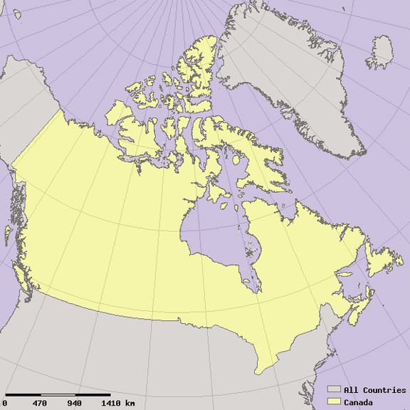
EXTENT -2400000 -900000 3100000 4000000
With these extents, MapServer produced the map shown in Figure 11-8. Grid lines were added to the map to show the difference in the shape of features that the projection change makes. Compare it to the regular rectangles in Figure 11-6.
Modifying Image Size to Better Fit the Extent of the Map
There is a lot of extra space on the left and right sides of the map in Figure 11-8. This can be easily fixed by changing the size of the map image.
This mapping application was originally set up to show the whole
world using a global project, which works great assuming the world map
is twice as wide as it is tall. The map SIZE setting has been 600×300 throughout
these exercises. That’s a width to height ratio of 2 to 1. The
previous map shows that Canada is roughly square using that LCC map
projection. You can change the size of your map to be roughly 1 to 1,
and the map will fit much better to the extents of Canada. Change the
size setting to something like 400×400 or 600×600, and see how it
looks. This is done by changing the SIZE setting near the beginning of the map
file: SIZE 600 600.
The resulting map is shown in Figure 11-9. Notice how much better Canada fits into the map image.
Before you can start mapping this, you need to change the image dimensions used in the HTML template file, global.html. The image width and height was hardcoded. To make the map more flexible, you can replace the hardcoded image dimensions with MapServer variables. This allows the HTML template to dynamically set the image dimensions based on the settings in the map file.
To use the MapServer variables instead, change line 7 in
global.html. Replace the width and height numbers
with the [mapwidth] and [mapheight] variables. It should look like
this:
<INPUT NAME="img" TYPE="image" SRC="[img]" width="[mapwidth]" height="[mapheight]" border=0 ALT="Map Image">
Likewise, you need to change the imgxy variable to automatically use the
center of the image instead of the hardcoded center pixel
value:
<INPUT type="hidden" name="imgxy" value="[mapcentroidx] [mapcentroidy]">
Warning
In cases where you need to hardcode the dimensions into the HTML template file, you must remember to keep the same dimensions in the HTML template and the map file. If the dimensions differ, it may not be apparent, but if you change the width/height ratio of the image enough, you will get a stretched or compressed map.
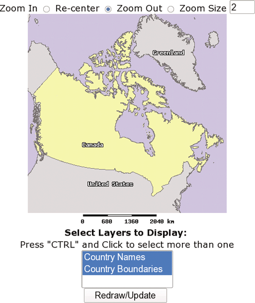
Adding Zoom and Recenter Tools to the Web Page
So far, the application has only one real tool. You can point and click to zoom in to an area. You haven’t been able to zoom out (other than by hitting the Back button in your web browser) or move the map sideways to recenter your view. Now you’ll add add three options to the web page, one for zooming in, another for zooming out and one to recenter the map on a new location.
If you are already familiar with HTML forms, this will be a snap. All you’re doing is adding an HTML form control that passes another CGI variable to the MapServer program. In the application so far, zooming was hardcoded. Instead, you will make a three-way option using three radio buttons.
Radio buttons are different from check boxes and normal buttons. When multiple radio buttons have the same name, only one can be selected at a time. This works perfectly for the task of selecting a single tool or option.
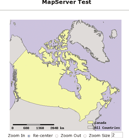
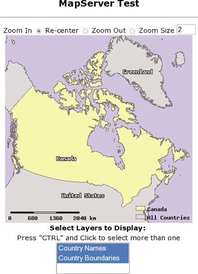
Example 11-7 shows the modified HTML template file, global.html, and Figure 11-10 shows the resulting web page from the exercise.
<HTML>
<HEAD><TITLE>MapServer Test</TITLE></HEAD>
<CENTER><H2>MapServer Test</H2>
<hr>

<FORM method=GET action="/cgi-bin/mapserv">
  <INPUT NAME="img" TYPE="image" SRC="[img]" width="[mapwidth]" height="[mapheight]"
               border=0 ALT="Map Image">
  <BR>

  Zoom In
  <INPUT type=radio name=zoomdir value=1 [zoomdir_1_check] >

  Re-center
  <INPUT type=radio name=zoomdir value=0 [zoomdir_0_check] >

  Zoom Out
  <INPUT type=radio name=zoomdir value=-1 [zoomdir_-1_check] >

  Zoom Size
  <INPUT type=text name=zoomsize size=4 value=[zoomsize]>

  <!-- Remove the following three lines
  <INPUT type=hidden name=zoomdir value=1 [zoomdir_1_check] >
  <INPUT type=hidden name=zoomsize size=4 value=[zoomsize]>
  -->

  <INPUT type="hidden" name="imgxy" value="[center_x] [center_y]">
  <INPUT type="hidden" name="imgext" value="[mapext]">
  <INPUT type="hidden" name="map" value="[map]">
  <INPUT type="hidden" name="savequery" value="true">
  <INPUT type="hidden" name="mapext" value="shapes">

</FORM></CENTER></BODY></HTML>
First, the radio button settings were added to the form. These are spaced out in the code example to try to show them more clearly. All three are very similar. Text will be shown beside the button, and the form code defines what each button does. The first two changed lines are formatting and labeling of the button:
<BR>
Zoom In
The <BR> tag acts as a
new line, so that the tools are displayed underneath the map image.
The words Zoom In start on a new line and are next to the
radio button itself. The radio button is defined by the tag:
<INPUT type=radio name=zoomdir value=1 [zoomdir_1_check] >
The <INPUT...> tag is
part of the CGI form on this page. It has three settings:
type=radioThis defines what kind of control is put on the form. So far in these examples,
type=hiddenhas been used. This doesn’t put a control on the form for the viewer but keeps a setting behind-the-scenes as if the control was invisible. In this caseradiospecifies that you want a radio button in this location. There are three radio buttons added on this page. They are all part of the same group, but only one can be selected at a time.name=zoomdirThis is the name of the variable. This variable will hold the value defined in the next option. The
name(andvalue) is passed on to the MapServer program and used to create the next map, depending on what button was selected.value=1This is the value the button has. Each button has a different value (-1, 0, 1). This value is sent with the above
name, which is passed to the MapServer program to interpret. Ifzoomdir=1, MapServer zooms in to the map. If it is-1, it zooms out. If it is0, it recenters the map to the location that is clicked.
The final piece of text in the INPUT tag is: [zoomdir_1_check]. This is a piece of text
that is replaced by MapServer when the HTML page is created. This is
similar to the [img] variable used
to draw the map in the page. MapServer replaces these placeholders
with values after creating the map. In this case, it replaces the text
with the word checked beside the
button that was pressed last. If you click on Zoom In, then click on
the map, it should zoom in to where you clicked on the map. At that
point the Zoom In tool will still be selected. That is because it is
now marked as checked. You can see
this in the HTML behind the page showing the map:
<INPUT type=radio name=zoomdir value=1 checked >If you select the Re-center button, it marks the second radio
button with the checked
setting:
<INPUT type=radio name=zoomdir value=0 checked >This allows the web browser to maintain the options you selected when it draws a new map or refreshes the page.
The only other line added was to enable the box to enter in a Zoom Size:
               Zoom Size
  <INPUT type=text name=zoomsize size=4 value=[zoomsize]>
This setting tells MapServer how much to zoom in (or out) when a
user clicks on the map. For example, a zoom size of 2 doubles the
scale and makes features on the map appear twice as large. This was
hardcoded into a hidden variable before adding the controls. These
lines can now be removed from the HTML template. The zoomdir setting was also hardcoded to
value=1, so that any time a user
clicked on the map it only zooms in. With the new controls just added,
these lines are no longer required:
               <INPUT type=hidden name=zoomdir value=1 [zoomdir_1_check] >
  <INPUT type=hidden name=zoomsize size=4 value=[zoomsize]>
One change is also required in index.html.
In the earlier examples, the default action was to zoom in. You had to
set the hidden zoomdir variable to
value=1, which MapServer interprets
as zoom in. By changing this to value=0 (zero), it makes the default action
be recenter instead of zoom. This will become more important by the
end of this chapter when we study the redraw button. If you hit
redraw, and zoom in is selected by default, the map will not only
redraws, but also zooms in. Here is the changed line in
index.html:
<INPUT type="hidden" name="zoomdir" value=0>
Tip
It is a good idea to move your HTML code around so it is the
most readable to you. Putting in spaces makes clear breaks for
discussion here, but HTML has very few formatting rules. You can add
or remove spaces between lines and words and even put the code into
one long line if you really want to. Indenting can help keep it
readable as well. Using the break tag <BR> or paragraph tag <P> is needed for putting different
controls onto different lines. Try putting <BR> before each of the INPUT radio buttons.
Adding a List of Layers to Choose From
Zoom and recenter features are critical for most web mapping applications. Many users also like the ability to control what layers they see. Those using the application will need some level of control. Being able to turn layers on and off is a key part of many MapServer applications. Try to give users as much freedom to explore their maps as possible, but also try to prevent them from making major mistakes. For example, if you give complete control and allow them to turn off every layer, the map will be empty. They got what they asked for but may think that your application is broken. You will have to decide how important complete control is versus having things a bit more restrictive but predictable.
Before you get into setting up layer selection options, you need
to create a new layer in the global mapping application. You could
find some images to include or another shapefile showing the locations
of places of interest. To keep it simple, the following example is
going to create a layer that shows text labels for the countries. You
can do this using the same countries_simpl
shapefile dataset that is already being used in the application. Example 11-8 shows the new
layer created in global.map. The new layer is
called country_labels. Instead of
drawing polygons or lines, tell it to only draw labels by setting
TYPE ANNOTATION.
  LAYER
    NAME country_labels
    TYPE ANNOTATION
    STATUS DEFAULT
    DATA countries_simpl
    LABELITEM 'NAME'
    CLASS
      LABEL
        COLOR 255 255 255
        OUTLINECOLOR 0 0 0
        POSITION CC
        MINFEATURESIZE 100
      END
    END
    PROJECTION
      "proj=latlong"
      "proj=WGS84"
    END
  END
With MapServer, you can set layers to be drawn two ways. One way
is to force the map to always draw the layer. This is done by setting
the layer to STATUS DEFAULT. The other way is to have it turned
on only when requested. In this case you can set it to STATUS OFF. If a layer is set to OFF in the map file, it doesn’t mean it will
never be drawn. If the layer is requested to be drawn by the web page,
then it will be.
Right now there are two layers in the map file: countries and country_labels. To have the country
boundaries always shown, leave the countries layer STATUS set to DEFAULT. But for country_labels, set it to STATUS OFF. This allows the user to turn off the
labels.
Warning
There is a third option, STATUS ON, which confuses many new MapServer
application developers. For the purposes of this tutorial, and if
you are just beginning, it’s probably a good idea to stick with
using OFF or DEFAULT. The ON setting will become more useful if you
use MapScript. For more about MapScript see Chapter 14.
The next place you make changes is in the
index.html page. The settings in this page tell
MapServer which layers to draw when drawing the first map. This is
different from setting the layer to be on by default in the map file.
Instead, the index.html page will pass a list of
layers to draw through to the MapServer program. If the layers are
available in the map file, it will request to see them. You will see
the names of the layers embedded in the URL as CGI values (e.g.,
&layers=countries). MapServer
uses these parameters to determine which layers to draw.
Back in Example 11-2 you saw the initial settings for index.html. That included this line:
<input type="hidden" name="layer" value="countries">
Having this line as part of the initialization form meant that
MapServer would be requested to draw the countries layer when the first map is drawn.
Considering that the layer is already set to draw by default, this
setting becomes redundant. countries will be drawn all the time anyway,
and the user won’t be able to turn it off. However, keep this line,
and copy it for use with the new layer that shows the labels:
<input type="hidden" name="layer" value="country_labels">Now when the map starts up, both layers will be drawn. If you
don’t want any layers other than those set with STATUS DEFAULT to be drawn, just remove any of the
lines in index.html, where name="layer".
The third place to set up layer options is in the HTML template file (global.html). MapServer puts the map image into this HTML page and displays any of the controls you want to have in your application, including a list of layers to choose from. This is the most labor-intensive part of the exercise, but it is important. This is where the user will actually see some options. The settings in global.map and index.html are hidden from the user (except in the URL) but anything shown in the HTML template page will be for the user to see.
The HTML template page already has a form defined on it. All you
need to do is add in a few more controls, also known as select
options. To have these displayed on the right side of the map, put the
code right after the <INPUT...> tag that draws the map.
Make sure there are no line breaks <BR> between the select controls and
the map if you want them to be side by side. Make sure that a <BR> tag follows the select list so
that the zoom/recenter controls are below everything else. Example 11-9 shows the first
few lines of HTML, including the start of the SELECT tag which is needed for the layer
list.
... <FORM method=GET action="/cgi-bin/mapserv"> <BR> <INPUT NAME="img" TYPE="image" SRC="[img]" width="[mapwidth]" height=" [mapheight]" border=0 ALT="Map Image"><SELECT multiple name="layer" size=3><!--the list of layers to chose from will go here --></SELECT><BR> Zoom In <INPUT type=radio name=zoomdir value=1 [zoomdir_1_check] > ...
Tip
The size=3 setting for the
SELECT tag determines how many
lines will be shown in the list. If you only have a few layers to
put in the list, you can set the size to equal the number of layers
you have available. If you have more than will easily fit in the
list, the list will still include them, but you have to scroll
through the list to find them. Using three makes it easier to see
that this is a list.
So far the list won’t do anything. Next you need to add an entry
for the country_labels layer. You
should also add some text that will be displayed near the list to
describe what the list is showing. Each layer that you want to show in
the list needs an <OPTION...>
tag like this:
<OPTION value="country_labels" [country_labels_select]>Country Names</OPTION>
The pieces specific to the application have been highlighted.
The first setting, value="country_labels", is the name of the
layer that will be drawn when this entry is selected from the
list.
Tip
If you are using groups in your map file, this could also be
the group name. In addition to a NAME setting, each LAYER can have a GROUP setting. This allows you to control
multiple layers using a single group name instead of many single
layer names.
The second setting [country_labels_select] is necessary for the
web page to highlight layers you have selected on previous maps. This
is similar to the checked settings
used when creating the radio buttons for zoom/recenter. This setting
should be the same as the value setting, but with _select added to it.
Warning
Typos in these two settings can really leave you confused and frustrated, so be careful to match the text to your layer name exactly.
The third item added is the text Country Names. This is outside of the <OPTION...> tag and is text to be
written on the web page. The text put here can be whatever you want it
to be. It will be used as a label for this layer in the select list on
the web page. With all these changes, the new web page looks like
Figure 11-11.
The complete global.html file looks like Example 11-10. In the final global.html, some text describing how to use the list and what it is for has been added. A few of the tags are moved around to make the page a bit more structured.
<HTML>
<HEAD><TITLE>MapServer Test</TITLE></HEAD>
<CENTER><H2>MapServer Test</H2>
<HR>

<FORM method=GET action="/cgi-bin/mapserv">
    Zoom In <INPUT type=radio name=zoomdir value=1 [zoomdir_1_check] >
    Re-center <INPUT type=radio name=zoomdir value=0 [zoomdir_0_check] >
    Zoom Out <INPUT type=radio name=zoomdir value=-1 [zoomdir_-1_check] >
    Zoom Size <INPUT type=text name=zoomsize size=4 value=[zoomsize]><BR>
  <INPUT NAME="img" TYPE="image" SRC="[img]" width="[mapwidth]" height="[mapheight]"
  border=0 ALT="Map Image"><BR>
  <B>Select Layers to Display: </B><BR>
	  Press "CTRL" and Click to select more than one<BR>
  <SELECT multiple name="layer" size=3>
    <OPTION value="country_labels" [country_labels_select]> Country Names</OPTION>
    <OPTION value="countries" [countries_select]> Country Boundaries</OPTION>
  </SELECT>

  <INPUT type="hidden" name="imgxy" value="[center_x] [center_y]">
  <INPUT type="hidden" name="imgext" value="[mapext]">
  <INPUT type="hidden" name="map" value="[map]">
  <INPUT type="hidden" name="savequery" value="true">
  <INPUT type="hidden" name="mapext" value="shapes">

</FORM></CENTER></BODY></HTML>
The natural next question is, how do you make the map redraw
after choosing new layers? You can use the zoom or recenter tools, and
it will update the map, reflecting this change, but this is hardly
intuitive. The easiest way is to add a button to the page that
requests a new map. HTML forms have a submit button you can use. Add
this code to global.html, right after the end of
the select list </SELECT>:
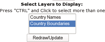
<BR><INPUT type="submit" value="Redraw/Update">
Now a button will appear right under the select list, as shown in Figure 11-12. You can select or deselect a layer, press the button, and see the change on the new map.
Congratulations. You have created your own interactive web mapping applications. There is a lot more to learn but you know the basics of creating interactive maps. The rest of the chapter provides a few more tweaks and tips for further developing your application.
Adding a Legend to the Application
A legend is another key component of web mapping application and is very simple to add. It only takes a minute to modify your code to add a legend graphic to the page. The legend is a small graphic showing what colors and styles are being used to draw the map layers. So far in this example application you’ve used an embedded legend that is part of the map image. Now you will pull that legend out of the map image and have it drawn separately on the page. This requires two changes: one modification of the global.map file to remove the embedded legend and an addition to the global.html file to draw the legend on the page.
Removing the embedded legend from the map file
An embedded legend is often used for compactness and
neatness, though a separate graphic showing the legend outside of
the map image may sometimes be preferred. In order to do this,
disable the embedded legend and set it to be a normal legend. This
is done by changing the STATUS
EMBED to STATUS ON in the LEGEND object of the map file. The
POSITION and TRANSPARENT keywords are unnecessary
because they don’t really apply anymore, so they can be removed as
well. Example 11-11
shows the original LEGEND object
of the global.map file, followed by the
modified version.
# Original legend
  LEGEND
    STATUS EMBED
    POSITION LR
    TRANSPARENT TRUE
  END
#-------------------
# Modified legend
  LEGEND
    STATUS ON
  END
Behind the scenes, this will create a separate image file showing the legend graphic.
Adding the legend graphic to the web page
Making this new legend appear on the web page requires a small piece of code to be added to the map template. You can add the code in Example 11-12 to global.html, in any spot you like.
<BR><HR>
<B>Legend</B><BR>
<IMG src="[legend]" alt="Map Legend"><HR>
Tip
This web page isn’t pretty, but it does work. Organize your page and add frames, HTML divs, etc. to make it look suitable for your audience.
This code places an image into the web page. It is very common
in web publishing. For example, take your favorite web site that
shows pictures and select the web browser’s View > Page Source
(or Document Source depending on which browser you use). This shows
the underlying HTML code behind the page. Nine times out of ten
there will be a similar <IMG> tag in there to display a
graphic.
Tip
The alt="Map Legend" part
of the code can be omitted. However, to meet the HTML standards,
you must have this attribute set. It provides a short, textual
description of the image. This is used by people who can’t render
the images or who are using a text-only browser.
Put the code in Example 11-12 right after
the redraw button. The magical piece of this code is the use of
src="[legend]". The src setting, in other types of web pages,
points to the location of an image file. Its usage is no different
in this application, except that MapServer automatically fills it in
for you. MapServer creates uniquely named temporary image files.
MapServer creates this image file on the fly, as the map is created,
and creates a new file every time. The [legend] code is replaced with the actual
path and name of the legend image file that it created. It then
sends this page to you, ready for your browser to load in the image.
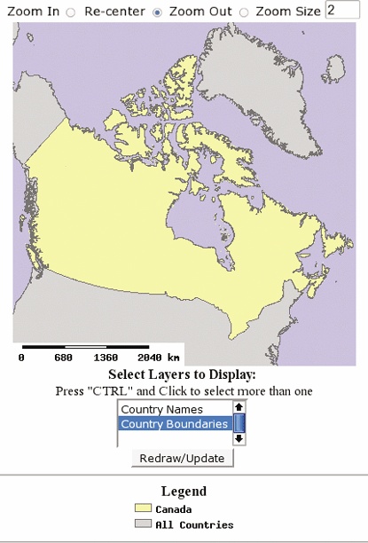
The final result is a web page that looks like Figure 11-13.
Adding a link to the legend image
The [legend]
setting in global.html can be used as a URL to
the legend graphic just as if it were the URL. This is useful if
your legend is very long and doesn’t fit well on the same page as
the map. It is very simple to create a link a viewer can click to
see the legend. This can save some space on the main map page. Using
the <A> tag to create a
simple link looks like this:
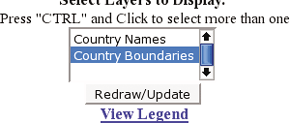
<A HREF="[legend]" TARGET="_blank"><B>View Legend</B></A>
The words View Legend
appear as a link to the image file itself, as in Figure 11-14. When the
user clicks on it, the image is viewed on its own page in the web
browser.
Adding a Scale Bar to the Application
Scale bar images are created through the same process as legend
images. When the scale bar isn’t used as an embedded image, it is
created as a separate image. MapServer then inserts it into the HTML
template wherever it finds the [scalebar] variable.
To global.html add one simple line, just like with the legend. Place it below the map image so that it is near enough to be useful for measuring. This is shown in Example 11-13.
<INPUT NAME="img" TYPE="image" SRC="[img]" width="[mapwidth]" height="[mapheight]"
             border=0 ALT="Map Image"><BR>

<IMG src="[scalebar]" alt="Map scale bar"><BR>

<B>Select Layers to Display: </B><BR>
In the SCALEBAR object of the
global.map file, change STATUS EMBED to STATUS ON
so that the scale bar is no longer shown on the map image
itself.
The final outcome looks like Figure 11-15.
Adding an Overview/Reference Map to the Application
Just like a legend and scale bar, a reference map image can be created at the same time as a map and added to your application. This requires a bit more forethought and some preparation. You need to keep in mind the purpose of your reference map. Typically, it is used for two purposes.
The primary purpose is showing where you are zoomed in to, relative to the original extent of the map. For example, Figure 11-16 shows a MapServer-based web site (http://www.gommap.org) that uses a reference map to orient users to their current view of the map.
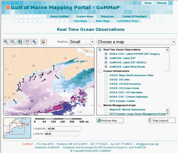
Reference maps can also be used to recenter the main map. If you want to view a different area, just click on the reference map, and the main map will recenter on that location. This feature is particularly helpful when you want to maintain the scale of your map but move to another location. Rather than using the recenter tool on the main map over and over again, just one click in the reference map takes you there.
Adding a reference map to your application follows a similar
process to adding a legend or scale bar. You add a REFERENCE object to your map file and some
code to the HTML template (e.g., global.html).
The only other requirement is an image file to use for the reference
map. It isn’t generated with a map file or layers but is a static
background map image.
You can download a small world map image in PNG or GIF format from:
The image is shown in Figure 11-17.
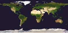
Now, save the image in the same folder as the
global.map map file. Add the code highlighted in
Example 11-14 to the
map file. I recommend you do so somewhere near the beginning. In this
example, it is shown between the LEGEND and PROJECTION objects.
...
  LEGEND
    STATUS EMBED
    POSITION LR
    TRANSPARENT TRUE
  END

  REFERENCE
    STATUS ON
    IMAGE keymap.png  # This could be keymap.gif instead
    EXTENT -180 -90 180 90
    SIZE 241 121
    COLOR -1 -1 -1
    OUTLINECOLOR 255 0 0
  END

  PROJECTION
    "proj=latlong"
...
The reference image file doesn’t have geographic coordinates
saved in the file. Instead, you must specify what the extent
coordinates are using the EXTENT
setting. This tells MapServer that the keymap.png
image covers the globe. The SIZE
setting tells how wide and tall the image is (in pixels). These two
settings allow MapServer to find a specific coordinate location on the
reference map image. If your reference map doesn’t seem to work
properly, one of these two settings may be incorrect.
When the reference map is used, it draws a rectangle on top of
the keymap.png image. The COLOR setting sets what color that rectangle
will be. It is red by default. COLOR -1
-1 -1 tells MapServer to not color the
rectangle, but to make it transparent. The OUTLINECOLOR setting gives the rectangle a
red outline.
The REFERENCE object doesn’t
have projection settings. This means that the EXTENT is always specified in the same units
as the output map projection. This example really only works with a
map that is displayed in the lat/long projection used at the beginning
of this chapter. Also, the extents will not be specified in meter
units for the LCC projection used earlier. Instead, the units must be
set to UNITS DD for this example to
work. The map EXTENT will need to
be in decimal degrees.
The global.html template file needs to be
modified as well. There are two ways to do this. The first is to
include another <IMG> tag,
like <IMG SRC="[ref"]>. This creates a simple
reference map. The other way to add the reference map lets you click
on the reference map to recenter your map. Use this code instead of
the previous:
<INPUT name="ref" TYPE="image" SRC="[ref]" width="241" height="121" ALT="Reference map">
This shows the image and also sets it up to take a click and change the main map image. If you add it right after the main map image, you will have a web page that looks similar to Figure 11-18. All the layer controls have been removed, and the legend and scale bar were switched back to embed.