Table of Contents for
ARM Assembly Language, 2nd Edition
 ARM Assembly Language, 2nd Edition
Published by
Chapman and Hall/CRC, 2016
ARM Assembly Language, 2nd Edition
Published by
Chapman and Hall/CRC, 2016
- Contents
- ARM Assembly Language: Fundamentals and Techniques, Second Edition
- Preliminaries
- To our families
- Preface
- Acknowledgments
- Authors
- Chapter 1 - An Overview of Computing Systems
- Chapter 2 - The Programmer’s Model
- Chapter 3 - Introduction to Instruction Sets: v4T and v7-M
- Chapter 4 - Assembler Rules and Directives
- Chapter 5 - Loads, Stores, and Addressing
- Chapter 6 - Constants and Literal Pools
- Chapter 7 - Integer Logic and Arithmetic
- Chapter 8 - Branches and Loops
- Chapter 9 - Introduction to Floating-Point: Basics, Data Types, and Data Transfer
- Chapter 10 - Introduction to Floating-Point: Rounding and Exceptions
- Chapter 11 - Floating-Point Data-Processing Instructions
- Chapter 12 - Tables
- Chapter 13 - Subroutines and Stacks
- Chapter 14 - Exception Handling: ARM7TDMI
- Chapter 15 - Exception Handling: v7-M
- Chapter 16 - Memory-Mapped Peripherals
- Chapter 17 - ARM, Thumb and Thumb-2 Instructions
- Chapter 18 - Mixing C and Assembly
- Appendix A: Running Code Composer Studio
- Appendix B: Running Keil Tools
- Appendix C: ASCII Character Codes
- Appendix D
- Glossary
- References
Chapter 17
ARM, Thumb and Thumb-2 Instructions
17.1 Introduction
Throughout the book, we’ve been using two different instruction sets, ARM and Thumb-2, only mentioning 16-bit Thumb here and there. Recall that the Cortex-M4 executes only Thumb-2 instructions, while the ARM7TDMI executes ARM and 16-bit Thumb instructions. Keeping in mind that a processor’s microarchitecture and a processor’s instruction set are two different things, Table 17.1 shows how the ARM processor architectures have evolved over the years, along with the instruction sets. They often get developed at the same time, but it is possible for a given microarchitecture to be modified only slightly to support additional instructions, adding more control logic and a bit more datapath, adding registers, etc. Consider the ARM9TDMI which supports the version 4T instruction set and the ARM9E, loosely the same microarchitecture, which supports version 5TE instructions. So when we discuss a processor like the Cortex-A15, we think of pipeline depth, memory management units, cache sizes, and the like, but at the end of the day we’re really interested in what instructions the machine supports. Historically for most ARM cores, two instruction sets were supported at the same time—ARM and Thumb—where the processor could switch between them as needed. In 2003, ARM (the company) introduced something called Thumb-2, and well, the water was muddied somewhat, so it’s worth a look back to see why there are now effectively three different instruction sets for ARM processors and in particular, which processors support any given instruction set.
Architectures and Instruction Sets
|
Version |
Example Core |
ISA |
|
v4T |
ARM7TDMI, ARM9TDMI |
ARM, Thumb |
|
v5TE |
ARM946E-S, ARM966E-S |
ARM, Thumb |
|
v5TEJ |
ARM926EJ-S, ARM1026EJ-S |
ARM, Thumb |
|
v6 |
ARM1136 J(F)-S |
ARM, Thumb |
|
v6T2 |
ARM1156T2(F)-S |
ARM, Thumb-2 |
|
v6-M |
Cortex-M0, Cortex-M1 |
Thumb-2 subset |
|
v7-A |
Cortex-A5, Cortex-A8,Cortex-A12, Cortex-A15 |
ARM, Thumb-2 |
|
v7-R |
Cortex-R4, Cortex-R5, Cortex-R7 |
ARM, Thumb-2 |
|
v7-M |
Cortex-M3 |
Thumb-2 |
|
v7E-M |
Cortex-M4 |
Thumb-2 |
17.2 ARM and 16-Bit Thumb Instructions
We’ve already seen what ARM instructions look like: they’re 32-bits long; they contain fields for specifying the operation, the source, and destination operands; they specify whether its execution is predicated upon a condition; etc. This format has also been around since the first ARM1 processor. Interestingly, most ARM processors support them, but not all. Again referring to Table 17.1, you can see that some processors, e.g., the Cortex-M4 and Cortex-M0, do not support 32-bit ARM instructions, but we’ll come back to this in a moment. In the early 1980s, many processors had either 8- or 16-bit instructions, so the question was eventually raised: can you compress a 32-bit instruction, keeping its code density improvements and features, to take advantage of inexpensive 16-bit memory and improve code density even further if you have 32-bit memory?
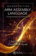
Reducing the size of existing instructions can be done by examining the operands and bit fields that are needed, then perhaps coming up with a shorter instruction. Consider the 32-bit pattern for ADD, as shown in Figure 17.1. Normally the required arguments include a destination register Rd, a source register Rn, and a second operand that can either be an immediate value or a register. A simple instruction that adds 1 to register r2, i.e.,
ADD r2, r2, #1
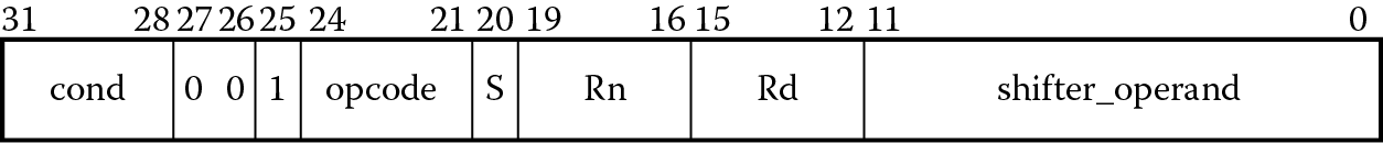
could be compressed easily, especially since the destination register is the same as the only source register (r2) used in the instruction. The other argument in the addition is 1, a number small enough to fit within an 8-bit field. If we enforce a few restrictions on the new set of instructions, the same operation can be done using only a 16-bit opcode, as shown in Figure 17.2, using Encoding T2, which would make the instruction appear as
ADD r2, #1
Now the source and destination registers are the same, so they can be encoded in the same field, and the 8-bit immediate value is 1. The other 16-bit format would allow ADD instructions that look like
ADDS r2, r3, #3
and
ADD r2, r4, #2
but again, with restrictions. Note the operand fields have changed from 4 bits to 3 bits, meaning the registers allowed range from r0 to r7, known as the low registers. To access the other registers, known as the high registers, separate instructions exist, including one that adds an immediate value to the Program Counter and two that add a value to the stack pointer. Note that the internal data paths and the registers in the processor would still be 32 bits wide—we’re only talking about making the instruction smaller.
This first deviation from the more traditional 32-bit ARM instructions is called Thumb, also referred to as 16-bit Thumb, and with it comes its own state (not to be confused with mode) in the processor. The instructions are a subset of the ARM instruction set, meaning that not all of the instructions in ARM are available in Thumb. For example, you cannot access the PSR registers in Thumb state on an ARM7TDMI. There are other restrictions on the use of constants, branches, and registers, but fortunately all of the subtleties in Thumb are left to the compiler, since you should rarely, if ever, be coding 16-bit Thumb instructions by hand. It is simply an option to give to the compiler. C or C++ code compiled for Thumb is typically about 65–70% of the size of code compiled for ARM instructions. Fewer instructions necessitates the use of more individual Thumb instructions to do the same thing ARM instructions can do. In practice, code is a mix of ARM and Thumb instructions, allowing programmers to base their use of Thumb instructions on the application at hand, as we’ll see in Section 17.5. In some cases, it may be necessary to optimize a specific algorithm in Thumb, such as a signal processing algorithm. Further optimizations would require knowing details of Thumb pretty well, and these can be found in the ARM Architectural Reference Manual (ARM 2007c) with the complete list of instructions and their formats.
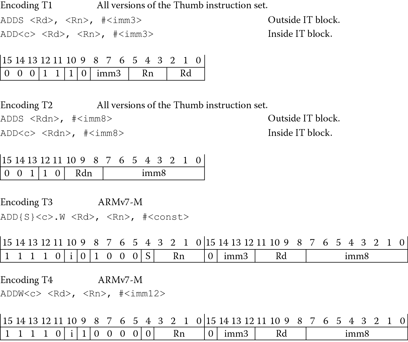
To demonstrate another advantage of having such an instruction set, an industry benchmark such as Dhrystone can be run on three different types of memory systems: 32-bit memory, 16-bit memory, and a mix of the two. Performance numbers are shown in Figure 17.3, where Dhrystone normally measures the number of iterations of the main code loop per second. For the case where the memory system is made of 32-bit memory only, ARM code clearly performs better than Thumb code, since Thumb must compensate for the loss of some operations by using more than a single instruction. When the system is changed to use 16-bit memory, Thumb code now has the advantage over ARM—it takes two cycles to fetch a complete ARM instruction from 16-bit accesses. Obviously, the performance has decreased for both ARM and Thumb over the original 32-bit configuration. It turns out that if a small amount of 32-bit memory is used for stacks, along with 16-bit memory, the level of performance is nearly comparable to Thumb code running out of 32-bit memory alone. Stack accesses are data accesses, and regaining the ability to fetch 32 bits at a time (even with a 16-bit instruction) shores up the performance numbers. As we’ll see shortly, both the ARM7TDMI and the Cortex-M4 execute 16-bit Thumb instructions.
17.2.1 Differences between ARM and 16-Bit Thumb
In the creation of a new 16-bit instruction set, we’ve considered how an ARM instruction can be shortened by restricting the operands, but we still have to take into account other bits in the instruction, such as the S bit that tells it to set the condition codes in the status register, and the conditional field in bits 28 through 31 that allows the instruction to be conditionally executed. To account for the S bit, we could simply say that all ALU instructions set the status flags upon completion. This might be too limiting, so we could further say that depending on the registers used, some instructions will set the flags and some will not. For most data processing instructions, the flags are set by default. However, instructions that use the high registers (except for CMP) leave the flags unaffected, for example:
ADD r12, r4 ; r12 = r12 + r4, flags unaffected
ADD r10, r11 ; r10 = r10 + r11, flags unaffected
ADD r0, r5 ; r0 = r0 + r5, flags affected
ADD r2, r3, r4 ; r2 = r3 + r4, flags affected
To account for the conditional field bits, it’s necessary to remove conditional execution from 16-bit Thumb code entirely (but don’t worry, it comes back with Thumb-2). Branches, however, can still be executed conditionally, since leaving only unconditional branches in the instruction set would be very limiting.
One further restriction that hasn’t been mentioned is the lack of inline barrel shifter options available on ARM instructions. There simply isn’t enough room in sixteen bits to include an optional shift, so individual instructions have been included in the Thumb instruction set for shifts and rotates (e.g., ASR for Arithmetic Shift Right, ROR for Rotate Right, LSL for Logical Shift Left, and LSR for Logical Shift Right). It wouldn’t be realistic to expect a compressed instruction set to include every ARM instruction, so there are noticeable differences between the two sets (some of which we have discussed already). For starters, data processing instructions are unconditionally executed, so loops are not as elegant in Thumb, and the condition code flags will always be updated if you use low registers (r0 through r7). In fact, most of the instructions only act on the low registers, with the notable exceptions being CMP, MOV, and some variants of ADD and SUB.
When it comes to loading and storing data, 16-bit Thumb instructions impose several restrictions. For example, the only addressing modes allowed are
LDR|STR <Rd>, [<Rn>, <offset>]
with the option of two pre-indexed addressing modes: base register + offset register and base register + 5-bit offset (optionally scaled). Even the load and store multiple instructions are different. If you are working with low registers only, then the format
LDMIA|STMIA <Rb>, <low reg list>
can be used. However, for pushing data onto the stack,
PUSH <low reg list, {lr}>
is used instead. Similarly, for popping data off the stack and loading the Program Counter in the process, you can use
POP <low reg list, {pc}>
as we did in Chapter 13.
17.2.2 Thumb Implementation
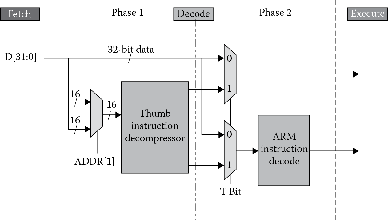
For the programmer, Thumb shouldn’t consist of much more than knowing it’s available and knowing how to compile for it. The compiler does all of the work by being told exactly which instruction set to use for any given block of code. However, it’s still worth understanding some of the modifications made within the ARM7TDMI architecture to support Thumb. While it’s tempting to think that disparate hardware was built specifically to support Thumb instructions, the only affected part of the ARM7TDMI pipeline is the decode stage, as shown in Figure 17.4. After the processor has fetched a Thumb instruction from memory, it goes through a multiplexor first, routing instructions through a programmable logic array (PLA) table, which expands the 16-bit binary pattern into an equivalent ARM instruction before being sent through the decode logic that follows. Afterwards, the encoding is treated exactly as any other instruction would be, necessitating only one decoder in this stage of the pipeline (the decode stage drives the datapath by generating control logic for various blocks within the processor). No penalty results from this extra step of decompression since the first half of the decode stage allows enough time for an instruction to go through the PLA logic (remember, the ARM7TDMI processors generally run at speeds less than 50 MHz). Longer pipelines have less time in each processor stage, so for processors built after the ARM7TDMI, all Thumb and ARM instructions are decoded in parallel—the decision to use only one set of the control signals generated by both decoders is based on the state of the machine. As we’ll see shortly, the Cortex-M processors that implement all or part of the version 7-M instruction set need only decode the instructions without worrying about whether they are ARM or Thumb instructions (although there is a certain amount of effort needed to decide whether the machine is looking at a 16-bit Thumb instruction or a 32-bit Thumb instruction). They are all Thumb instructions!
17.3 32-Bit Thumb Instructions
With pressure coming from industry standards (e.g., the image compression standard H.264) and applications, support for operating systems, and better handling of interrupts, it was time to reexamine what kinds of processors were possible using ARM, 16-bit Thumb, supersets, and even subsets of these instructions. In 2003, ARM decided to cross the Rubicon and build machines that would support instructions of varying width—some instructions would be 16 bits long and some would be 32 bits long. Part of the reasoning behind doing so was that processors being used in microcontroller applications required features that could not be supported with just a 16-bit instruction set, or even the existing ARM and Thumb instruction sets together. The 16-bit instructions had too many limitations to be used alone, and switching between the two instruction sets added extra cycles that could be better spent handling exceptions and interrupts. However, a compressed instruction set would be beneficial in a microcontroller that only had a limited amount of tightly coupled memory or cache.
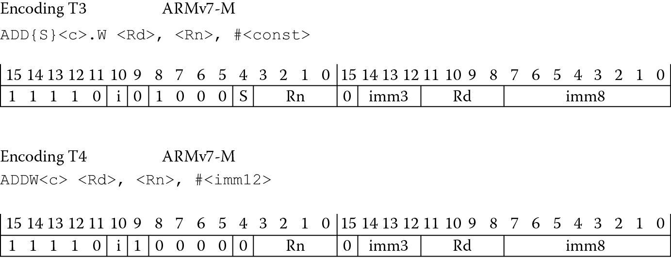
Even though the whole idea of instructions with a fixed length is sacrosanct in RISC architectures, with the introduction of 32-bit Thumb instructions, some of the limitations of 16-bit instructions disappear. Consider the two Thumb-2 ADD immediate instructions in Figure 17.5 (shown earlier as Encoding T3 and T4 in Figure 17.2). Now that the instructions contain 32 bits again, longer constants can be used, condition codes can be optionally set or not set, and the register fields’ width allows nearly all the registers to be used with a single instruction (there are minor exceptions). Because there was little room left in the Thumb instruction space, a new encoding would be required to indicate to a processor that a fetched 16-bit instruction was merely the first half of a new 32-bit instruction. It turns out that if you are in Thumb state and the upper three bits of an instruction are all ones and the following two bits are non-zero, the processor can figure out that there are two halves to an encoding. So room does exist in the instruction space for new operations. In other words, the processor can tell by the encoding of the upper five bits whether the instruction is 16 bits long or 32 bits long—if any of the following patterns are seen, it’s a 32-bit Thumb instruction:
- 0b11101
- 0b11110
- 0b11111
The newer 32-bit instructions were then combined with older 16-bit Thumb instructions to create something called Thumb-2. This more powerful instruction set eliminated the need to support two instruction sets. Microcontrollers specifically, which often require fast interrupt handling times, did not need to burn cycles switching states from Thumb back to ARM to process an exception. The processor can execute exception handlers and normal code with the same instruction set. If you further examine the ARM v7-M Architectural Reference Manual, you’ll find that extensions have since been added for DSP operations and floating-point support.
Referring to Figure 17.5, notice that it is now possible to choose whether to set condition codes with a Thumb instruction, and along with this flexibility comes a bit of potential confusion. With the adoption of a Unified Assembly Language (UAL) format, Thumb code and ARM code now look the same, leaving the choice of instruction to the assembler unless you tell it otherwise. For example, if you were to simply say
EOR r0, r0, r1
the operation could be performed using either a 16-bit Thumb instruction, an ARM instruction or a 32-bit Thumb instruction. If you happen to be working with a Cortex-M4, for example, then the choice falls to either one of the types of Thumb instructions, but there are two very subtle differences to mind. The first is that an ARM instruction of this type would not set the condition codes, since there is no S appendix in the mnemonic. A 16-bit Thumb instruction would set the condition codes. So using 16-bit Thumb instructions, the following two instructions would be equivalent:
EOR r0, r1 ; 16-bit Thumb
EORS r0, r0, r1 ; 16-bit Thumb using the UAL syntax
The second difference to mind is the directives themselves. To identify the more traditional 16-bit Thumb code using ARM tools, then you would use the directive CODE16; if you want to indicate that you are using UAL syntax, then you would use the directive THUMB in your assembly.
Example 17.1
Consider the following instruction and directive:
THUMB
EOR r0, r0, r1
You might be tempted think that an instruction like this (which sets the flags when using these low registers in traditional Thumb) could be done as a 16-bit Thumb instruction. However, since we’ve indicated to the assembler that we’re using UAL syntax by using the directive THUMB, the instruction has no S on the mnemonic and we are therefore telling the assembler not to produce an instruction which sets the condition codes. There is no 16-bit instruction in the Thumb instruction set to do this—the assembler is then forced to use a 32-bit Thumb-2 instruction (0xEA800001). This might not be what you want as you attempt to get better code compression. A good general rule is therefore: if you use UAL syntax, then always use an S on those operations that require updating the condition codes.
17.4 Switching Between ARM and Thumb States
The two processors that we’ve examined throughout the text, the ARM7TDMI and the Cortex-M4, are perfect examples of the variety that now exists in the ARM product lines. Some cores can execute ARM, Thumb, and Thumb-2 instructions. Some cores only execute Thumb-2. If you do happen to be using a processor that supports both ARM and Thumb instructions, the bulk of C/C++ code in embedded applications might be compiled for Thumb instructions, especially with its performance from narrow memory and its code density. However, there are still times when it will be necessary to switch between ARM and Thumb state. For example, on an ARM926EJ-S, certain operations cannot be done in Thumb state, so if access to the CPSR is needed to enable or disable interrupts, then the core must switch to ARM state. Speed-critical parts of an application may run in ARM state, since it gets better performance in 32-bit memory—a JPEG compression routine, for example, which is common in digital cameras. Processors such as the Cortex-M3 and Cortex-M4 always run in Thumb state, and it was mentioned in Chapter 8 that care must be taken to stay in Thumb state when creating your exception vector table and when doing any branching. Processors such the Cortex-R4, the Cortex-A15, and our venerable ARM7TDMI have more than a single state, so let’s examine how to switch between them.
If you recall from Chapter 2, there is a bit in the CPSR, the T bit, that indicates whether the processor is in ARM state or Thumb state. This is only a status bit (meaning it’s read-only), and switching between the two states is accomplished by way of a special type of branch instruction—BX, or branch and exchange. The formats for this instruction are
Thumb state: BX Rn
ARM state: BX{condition} Rn
where Rn can be any register.
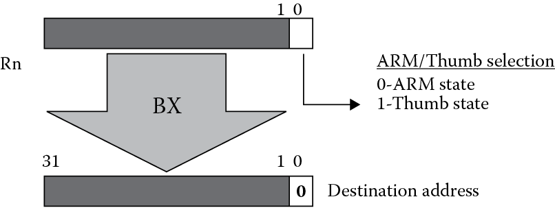
The mechanism used to switch between the states depends on an address held in Rn. Normally, the least significant bit of an address is ignored, since a branch to an unaligned address in both ARM and Thumb states is not allowed. By using bit 0 of Rn and the BX instruction, the state can be changed when the processor jumps to the new address. If bit 0 is a zero, the state is set to ARM; if bit 0 is a one, the state is set to Thumb, as shown in Figure 17.6.
When changing from Thumb to ARM state on the ARM7TDMI, it’s important to ensure that bit 1 of the address is also a zero—remember that ARM instructions are always fetched from word-aligned addresses, i.e., addresses that end in 0, 4, 8, or 0xC, so the two least significant bits of the address must be clear. One other important point worth considering is the register used. While the use of the PC as Rn in the BX instruction is valid, it’s not recommended, since unexpected results could occur. Depending on how the code is arranged, you can end up jumping to a misaligned address, and from there the system only gets muddled.
Example 17.2
Using the Keil tools, the following ARM7TDMI code shows an example of a state change from ARM to Thumb.
GLOBAL Reset_Handler
AREA Reset, CODE, READONLY
ENTRY
Reset_Handler
ARM
start ADR r0, into_Thumb + 1
BX r0
CODE16
into_Thumb
MOV r0, #10
MOV r1, #20
ADD r1, r0
stop B stop
END
Notice that the BX instruction is used to jump to an address called into_Thumb, where the least significant bit of the address has been set using the ADR pseudo-instruction. The short section of Thumb code begins with the directive CODE16, indicating the following instructions are Thumb instructions (the newer assembly format uses the directive THUMB). The Thumb code that follows just adds the numbers 10 and 20 together. When you run this example, examine the CPSR and notice that the T bit is set when the branch is made into Thumb code.
Cores that have only one instruction set, such as the Cortex-M3 or the Cortex-M4, do not have to worry about switching states. However, care must be taken to prevent switching states. For example, if you were to branch to an address contained in a register on the Cortex-M4, using the BX instruction say, and the least significant bit of that address was a zero, then a Usage fault gets generated since the processor cannot change states. This issue goes away if you are always coding in C or C++, or if your assembly code uses labels and pseudo-instructions to generate branch target addresses, since the tools will compute the correct values for you, even making them odd when necessary. If you generate addresses some other way or enter them by hand in your assembly code, then watch the least significant bit!
17.5 How to Compile for Thumb
A question that ultimately arises from introducing an instruction such as BX is how certain parts of ARM code might call a Thumb subroutine or vice versa. A section of code can be compiled as either ARM or Thumb code; however, calling and returning from a subroutine might require the ability to switch states. For example, if you were to write an ARM subroutine that called a Thumb subroutine, and these two sections of code were compiled separately without taking some necessary steps, then the ARM subroutine may not be able to switch to Thumb state before jumping, since a BL instruction does not change state. If you’re writing all of your own assembly, then obviously you need to mind the state of the machine when putting blocks of code together. However, embedded systems depend heavily on high-level coding, so it’s far more likely that you’ll be compiling C or C++ to incorporate Thumb code in your application.
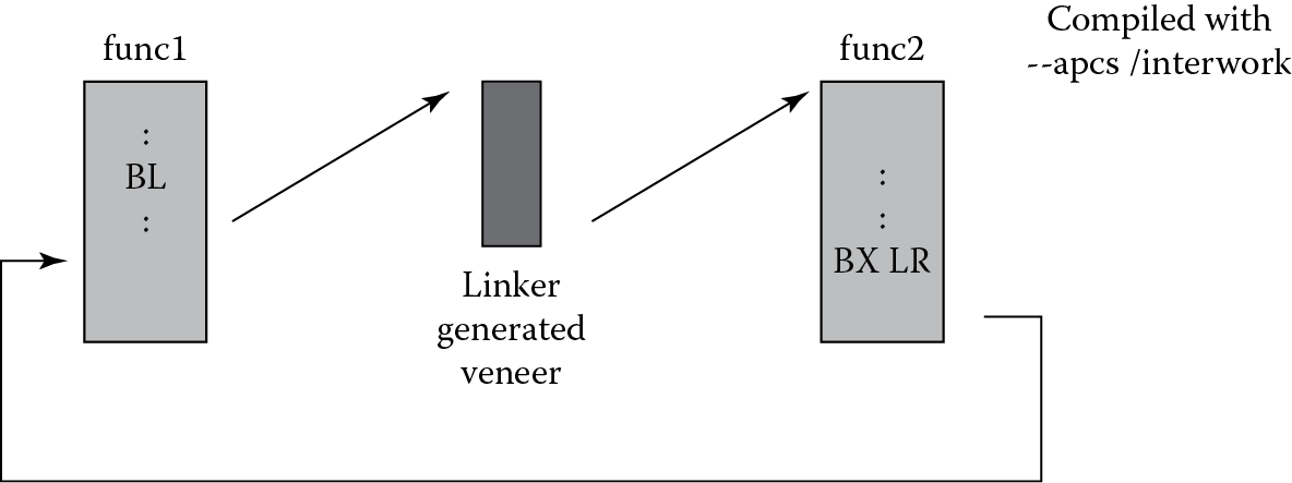
Fortunately, compiler options can aid in the use of both ARM and Thumb subroutines in the same program. The process is known as interworking, and it can be done through a short bit of code known as a veneer. To illustrate how this works, Figure 17.7 shows a subroutine call from func1 to func2, where the subroutine func1 is to be compiled for ARM and func2 is to be compiled for Thumb (remember that a function might be called from either state). The BL instruction will not change the state before the jump is made, and the instructions that are normally used to return from a subroutine, i.e.,
MOV PC, LR
will also not change the state. Therefore, veneers are created to aid in the task of switching between ARM and Thumb. These short blocks of code (usually 8–12 bytes) become the immediate target of the original branch instruction, and include a BX instruction to change the state, e.g.,
ADR r12, {PC} + offset
BX r12
If the two blocks func1 and func2 are compiled with the --apcs/interwork option (for the ARM tools), an interwork attribute is set on the code generated, which will in turn be picked up by the linker. The linker will then calculate the offset and insert the veneer in the final code automatically. The called function, func2, also returns to the main code via a
BX LR
instruction instead of using the Thumb POP instruction, which would load the caller’s return address from the stack and move it into the PC. In Thumb, the instruction
BX LR
will always return to the correct state (irrespective of whether a Thumb or ARM function called the subroutine). The BL instruction in Thumb sets the least significant bit of the return address, which would cause problems if the machine was originally in ARM state. Should you decide to mix assembly in C/C++ code, using the/interwork option will not change your assembly code, but it will alert the linker that your code is compatible for interworking. You would, however, be expected to use the correct return instruction (BX LR) in your own code. Consult the documentation for the tool suite you are using on the rules and usage of ARM/Thumb interworking.
If you are using a processor that does not switch between ARM and Thumb instructions, then by steering the compiler toward the appropriate architecture, the correct assembly will be generated automatically. For example, if you happen to be using the Keil tools to compile code for a Cortex-M4-based microcontroller, you will find the assembler option
--cpu Cortex-M4.fp
in the command line to tell the assembler that the v7-M instruction set is to be used along with floating-point instructions. No veneers are needed, since the machine never has to change states.
17.6 Exercises
- On the ARM7TDMI, which bit in the CPSR indicates whether you are in ARM state or Thumb state?
- Give the mnemonic(s) for a 16-bit Thumb instruction(s) that is equivalent to the ARM instruction
SUB r0, r3, r2, LSL #2
- Why might you want to switch to Thumb state in an exception handler?
- Can you talk to a floating-point coprocessor in Thumb state?
- Using Figure 17.2 as a guide, convert Program 3 from Chapter 3 into 16-bit Thumb assembly.
- Describe why veneers might be needed in a program.
- Convert Example 13.4 into 16-bit Thumb code. Do not convert the entire subroutine—just the four lines of code to perform saturation arithmetic.
- In which state does the ARM7TDMI processor come out of reset?
- How do you switch to Thumb state if your processor supports both ARM and Thumb instructions?
- How do you switch to ARM state on the Cortex-M4?