Table of Contents for
ARM Assembly Language, 2nd Edition
 ARM Assembly Language, 2nd Edition
Published by
Chapman and Hall/CRC, 2016
ARM Assembly Language, 2nd Edition
Published by
Chapman and Hall/CRC, 2016
- Contents
- ARM Assembly Language: Fundamentals and Techniques, Second Edition
- Preliminaries
- To our families
- Preface
- Acknowledgments
- Authors
- Chapter 1 - An Overview of Computing Systems
- Chapter 2 - The Programmer’s Model
- Chapter 3 - Introduction to Instruction Sets: v4T and v7-M
- Chapter 4 - Assembler Rules and Directives
- Chapter 5 - Loads, Stores, and Addressing
- Chapter 6 - Constants and Literal Pools
- Chapter 7 - Integer Logic and Arithmetic
- Chapter 8 - Branches and Loops
- Chapter 9 - Introduction to Floating-Point: Basics, Data Types, and Data Transfer
- Chapter 10 - Introduction to Floating-Point: Rounding and Exceptions
- Chapter 11 - Floating-Point Data-Processing Instructions
- Chapter 12 - Tables
- Chapter 13 - Subroutines and Stacks
- Chapter 14 - Exception Handling: ARM7TDMI
- Chapter 15 - Exception Handling: v7-M
- Chapter 16 - Memory-Mapped Peripherals
- Chapter 17 - ARM, Thumb and Thumb-2 Instructions
- Chapter 18 - Mixing C and Assembly
- Appendix A: Running Code Composer Studio
- Appendix B: Running Keil Tools
- Appendix C: ASCII Character Codes
- Appendix D
- Glossary
- References
Chapter 13
Subroutines and Stacks
13.1 Introduction
Subroutines, which are routines dedicated to focused or shorter tasks, occur in nearly all embedded code, often to perform initialization routines or to handle algorithms that require handcrafted assembly. You’re very likely to write subroutines when you come across a large problem to solve. The notion of divide-and-conquer aptly applies to writing assembly code—it’s just easier to get your head around a problem by describing it as a sequence of events, worrying about the low-level details when you write the event itself. For example, you could break a large program that controls a motor into something that looks like
main BL ConfigurePWM
BL GetPosition
BL CalcOffset
BL MoveMotor
...
and then write each of the smaller tasks as subroutines. Even if you’re coding at a high level, say in C or C++, it’s natural to break down a large task into smaller blocks or functions, each function being a routine that can be called from a main routine.
To write a proper subroutine, we also have to look at ways of saving and restoring data, passing information to and from subroutines, and building stacks. This chapter will cover some instructions that we skipped in Chapter 5, the load and store multiple operations LDM and STM, and their synonymous mnemonics PUSH and POP, as they’re used frequently in stack operations. We’ll briefly look at ARM standards that govern stack creation and define a standard way to call subroutines, so that a common protocol exists for all developers. Without such standards, programmers could easily write code that is incompatible with code created using third-party tools, or even tools from ARM. Before writing any code, though, we have to look at those new instructions and define what we mean by a stack.
13.2 The Stack
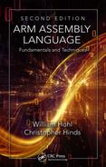
Stacks are conceptually Last In-First Out (LIFO) queues that can be used to describe systems from the architectural level down to the hardware level. Stacks can be used for software operations, too. More abstract descriptions of stacks can be used as data types by languages such as Java or Python, and there are even stack-based computer systems. When referring to hardware, generally these are areas in memory that have a variable length and a fixed starting address. Figure 13.1 shows a description of a hardware stack, with each entry being a fixed number of bytes in memory (for our case, generally these are word-length values). Data is written, or pushed, onto the top of the stack, and also read, or popped, from the top of the stack, where the processor adjusts the stack pointer before or after each operation. ARM processors have a stack pointer, register r13, which holds the address of either the next empty entry or the last filled entry in the queue, depending on what type of stack you have. We’ll see the different types shortly.
13.2.1 LDM/STM Instructions
Back in Chapter 5, we covered all of the basic load and store instructions, leaving off one pair until now—the load and store multiple instructions. Where LDR and STR instructions transfer words, halfwords, and bytes, the LDM and STM instructions always transfer one or more words using registers and a pointer to memory, known as the base register. This type of load/store appears most often in the context of stacks and exception handling, since the processor only has a limited number of registers, and at times, you just have to make some room for new data somewhere. By saving off the contents of the registers before handling an exception or going to a subroutine, you free up registers for different uses. Obviously, these must be restored when you’re finished, and there are instructions for doing exactly that. There are also advantages in using a multiple register transfer instruction instead of a series of single data transfer instructions, to wit, the code size decreases. A single LDM instruction can load multiple registers from memory using only a single instruction, rather than individual LDR instructions. Execution time also shortens, since only one instruction must be fetched from memory.
On the ARM7TDMI, the syntax of the LDM instruction is
LDM <address-mode> {<cond>} <Rn> {!}, <reg-list> {^}
where {<cond>} is an optional condition code; <address-mode> specifies the addressing mode of the instruction, which tells us how and when we change the base register; <Rn> is the base register for the load operation; and <reg-list> is a comma-delimited list of symbolic register names and register ranges enclosed in braces. We’ll talk more about the “!” and “^” symbols in a moment.
On the Cortex-M3/M4, the syntax of the LDM instruction is
LDM <address-mode> {<cond>} <Rn> {!}, <reg-list>
where {<cond>} is an optional condition code; <address-mode> specifies the addressing mode of the instruction (although as we’ll see in the next section, there are only two); <Rn> is the base register for the load operation; and <reg-list> is a comma-delimited list of symbolic register names and register ranges enclosed in braces.
Example 13.1
Suppose you wanted to load a subset of all registers, for example, registers r0 to r3, from memory, where the data starts at address 0xBEEF0000 and continues upward in memory. The instruction would simply be
LDMIA r9, {r0-r3}
where the base register r9 holds the address 0xBEEF0000. The addressing mode used here is called Increment After, or IA. This says to increment the address after each value has been loaded from memory, which we’ll see shortly. This has the same effect as four separate LDR instructions, or
LDR r0, [r9]
LDR r1, [r9, #4]
LDR r2, [r9, #8]
LDR r3, [r9, #12]
Notice in the example above that at the end of the load sequence, register r9 has not been changed and still holds the value 0xBEEF0000. If you wanted to load data into registers r0 through r3 and r12, you could simply add it to the end of the list, i.e.,
LDMIA r9, {r0-r3, r12}
Obviously, there must be at least one register in the list, but it doesn’t actually matter in what order you list the registers. The lowest register will always be loaded from the lowest address in memory, and the highest register will be loaded from the highest address. For example, you could say
LDMIA r9, {r5, r3, r0-r2, r14}
and register r0 will be loaded first, followed by registers r1, r2, r3, r5, and r14.
Analogous to the load multiple instruction, the store multiple instruction (STM) transfers register data to memory, and for the ARM7TDMI, its syntax is
STM <address-mode> {<cond>} <Rn> {!}, <reg-list> {^}
where the options are identical to those for the LDM instruction. The syntax for the Cortex-M3/M4 is
STM <address-mode> {<cond>} <Rn> {!}, <reg-list>
The options on LDM and STM instructions are used sparingly, but they’re worth mentioning here. Starting from the value in the base register, the address accessed is decremented or incremented by one word for each register in the register list. Since the base register is not modified after an LDM or STM instruction completes, you can force the address to be updated by using the “!” option with the mnemonic. If you happen to have the base register in the register list, then you must not use the writeback option. The caret (^) option is discussed in Chapter 14, since it relates more to the procedures of handling exceptions.
The addressing modes go by different names, as we’ll see in a moment, but basically there are four:
IA—Increment After
IB—Increment Before
DA—Decrement After
DB—Decrement Before
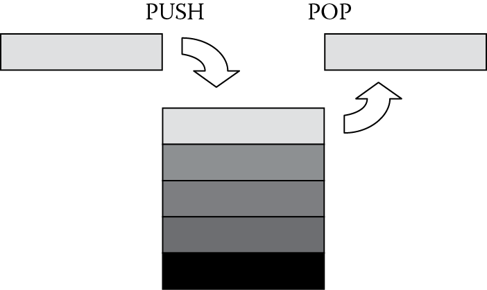
The suffix on the mnemonic indicates how the processor modifies the base register during the instruction. For example, if register r10 contained 0x4000,
LDMIA r10, {r0, r1, r4}
would begin by loading register r0 with data from address 0x4000. The value in the base register is incremented by one word after the first load is complete. The second register, r1, is loaded with data from 0x4004, and register r4 is loaded with data from 0x4008. Note here that the base register is not updated after the instruction completes. The other three suffixes indicate whether the base register is changed before or after the load or store, as well as whether it is incremented or decremented, as shown in Figure 13.2. In the following sections, we’ll examine stacks and the other addressing mode suffixes that are easier to use for stack operations.
While the ARM7TDMI supports all four addressing modes, version 7-M processors like the Cortex-M3/M4 have more restrictive options and a few cautions to mind. There are only two addressing modes from which to choose:
IA—Increment After
DB—Decrement Before
since the Cortex-M3/M4 supports only one type of stack, which we’ll examine more closely in the next few sections. If an LDM instruction is used to load the Program Counter, ensure that bit 0 of the loaded value is set to a 1; otherwise a fault exception occurs. For both the STM and LDM instructions, the stack pointer should not be included in the register list. Also be aware that if you have an LDM instruction that has the Link Register in the register list, you cannot include the Program Counter in the list. Consult the ARM v7-M Architectural Reference Manual (ARM 2010a) for other restrictions when using LDM and STM instructions.
13.2.2 PUSH and POP
There are two instructions that are synonymous with STMDB and LDMIA, namely PUSH and POP, respectively. PUSH can be used in place of a STMDB instruction with both the ARM7TDMI and the Cortex-M4, as it falls in line with the new preferred UAL mnemonics. The syntax for the two instructions is
PUSH{<cond>} <reglist>
POP{<cond>} <reglist>
where {<cond>} is an optional condition code and <reg-list> is a comma-delimited list of symbolic register names and register ranges enclosed in braces. PUSH has similar restrictions to the STM instruction, e.g., the register list must not contain the PC. POP has similar restrictions to the LDM instruction, e.g., the register list must not contain the PC if it contains the LR.
Example 13.2
PUSH and POP make it very easy to conceptually deal with stacks, since the instruction implicitly contains the addressing mode. Suppose we have a stack that starts at address 0x20000200 on the Tiva TM4C123GH6ZRB, grows downward in memory (a full descending stack), and has two words pushed onto it with the following code:
AREA Example3, CODE, READONLY
ENTRY
SRAM_BASE EQU 0x20000200
LDR sp, =SRAM_BASE
LDR r3, =0xBABEFACE
LDR r4, =0xDEADBEEF
PUSH {r3}
PUSH {r4}
POP {r5}
POP {r6}
stop B stop ; stop program
Figure 13.3
Figure 13.4
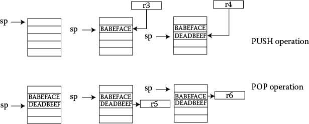
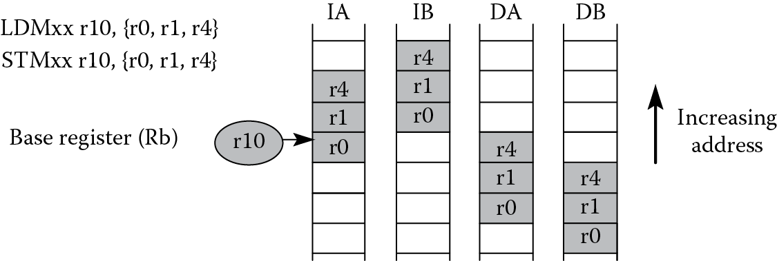
As we’ll see in the next section, a full descending stack implies that the stack pointer is pointing to the last (full) item stored in the stack (at address 0x20000200) and that the stack items are stored at addresses that decrease with each new entry. Therefore, our stack pointer must be decremented before anything new is placed on the stack. The first word in our program would be stored in memory at address 0x200001FC. The second word would be stored at address 0x200001F8. If you run the code above in a simulator and view a memory window, such as the one in Figure 13.3, you will see the two words stored at successively decreasing addresses. The POP instructions will read the data into whichever registers we choose, so the value 0xDEADBEEF is popped off the top of the stack into register r5. The stack pointer is incremented afterward. The second POP instruction moves the value 0xBABEFACE into register r6, shown in Figure 13.4, returning the stack pointer value to 0x20000200.
13.2.3 Full/Empty Ascending/Descending Stacks
Stack operations are easy to implement using LDM and STM instructions, since the base register is now just the stack pointer, register r13. Several types of stacks can be built, depending on personal preferences, programming, or hardware requirements. Your software tools will probably build a particular type of stack by default. Fortunately, they all use the same instructions—the differences lie with suffixes on those instructions. The options are
Descending or ascending—The stack grows downward, starting with a high address and progressing to a lower one (a descending stack), or upward, starting from a low address and progressing to a higher address (an ascending stack).
Full or empty—The stack pointer can either point to the last item in the stack (a full stack), or the next free space on the stack (an empty stack).
To make it easier for the programmer, stack-oriented suffixes can be used instead of the increment/decrement and before/after suffixes. For example, you can just use the FD suffix to indicate that you’re building a full descending stack; the assembler will translate that into the appropriate instructions. Pushing data onto a full descending stack is done with an STMDB instruction. The stack starts off at a high address and works its way toward a lower address, and full refers to the stack pointer pointing at the last item in the stack, so before moving new data onto it, the instruction has to decrement the pointer beforehand. Popping data off this type of stack requires the opposite operation—an LDMIA instruction. Because the address always points to the last item on the stack, the processor reads the data first, then the address is incremented. Refer to Table 13.1 for a list of stack-oriented suffixes.
Stack-Oriented Suffixes
|
Stack Type |
PUSH |
POP |
|
Full descending |
STMFD (STMDB) |
LDMFD (LDMIA) |
|
Full ascending |
STMFA (STMIB) |
LDMFA (LDMDA) |
|
Empty descending |
STMED (STMDA) |
LDMED (LDMIB) |
|
Empty ascending |
STMEA (STMIA) |
LDMEA (LDMDB) |
Example 13.3
Let’s build a full descending stack in memory, using register r13 as the pointer to the stack. Further suppose that this code is part of a routine that will require the Link Register and registers r4 through r7 to be saved on the stack. Assume that the SRAM starts at address 0x20000200 for the Tiva TM4C123GH6ZRB microcontroller. Our code might start something like this:
AREA Test, CODE, READONLY
SRAM_BASE EQU 0x20000200
ENTRY
; set up environment
LDR sp, =SRAM_BASE ;r13 = ptr to stack memory
;
; your main code is here
;
; call your routine with a branch and link instruction
BL Myroutine
;
Myroutine ; Routine code goes here. First, create space in the register
; file by saving r4-r7, then save the Link Register for the return,
; all with a single store multiple to the stack
STMDB sp!, {r4-r7,lr} ;Save some working registers
;
; Routine code
;
; Restore saved registers and move the Link Register contents
; into the Program Counter, again with one instruction
LDMIA sp!, {r4-r7,pc} ;restore registers and return
END
Recall that full descending stacks can be created by using the STMDB/LDMIA combination, identical to the PUSH/POP combination. Notice that the LDM instruction pops the value of the Link Register into the Program Counter, so if we were to call our stacking routine as part of another function, the return address is moved into the Program Counter automatically and fetching begins from there. This is exactly how subroutines are called, which brings us to our next section.
13.3 Subroutines
Most large programs consist of many smaller blocks of code, or subroutines, where functions can be called at will, such as a print routine or a complicated arithmetic function like a logarithm. A large task can be described more easily this way. Subroutines also allow programmers to write and test small blocks of code first, building on the knowledge that they’ve been proven to work. Subroutines should follow certain guidelines, and software should be able to interrupt them without causing any errors. A routine that can be interrupted and then called by the interrupting program, or more generally, can be called recursively without any problems, is called reentrant. By following a few simple procedures at the start of your code, you should be able to write reentrant subroutines with few headaches.
We’ve already seen a few examples of subroutines in Chapter 6, where the subroutine is called with the BL (branch and link) instruction. This instruction transfers the branch target (the starting address of your subroutine) into the Program Counter and also transfers the return address into the Link Register, r14, so that the subroutine can return back to the calling program.
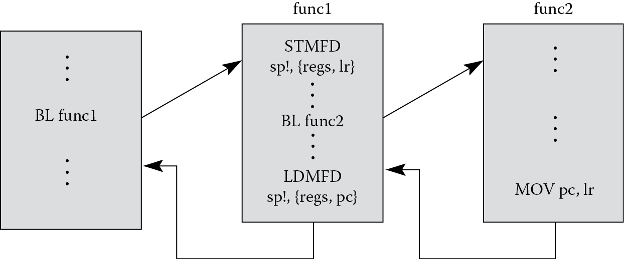
Subroutines can also call other subroutines, but caution must be taken to ensure information is not lost in the process. For example, in Figure 13.5, a main routine calls a subroutine called func1. The subroutine should immediately push the values of any registers it might corrupt, as well as the Link Register, onto the stack. At some point in the code, another subroutine, func2, is called. This subroutine should begin the exact same way, pushing the values of any used registers and the Link Register onto the stack. At the end of func2, a single LDM instruction will restore any corrupted registers to their original values and move the address in the Link Register (that we pushed onto the stack) into the Program Counter. This brings us back to point where we left off in subroutine func1. At the end of func1, registers are restored and the saved Link Register value coming off the stack is moved into the Program Counter, taking us back to the main routine. If func1 doesn’t save the Link Register at the start of its routine, when func2 is called, the Link Register will get overwritten with a new return address, so when func1 finishes and tries to return to the main routine, it has the wrong return address.
13.4 Passing Parameters to Subroutines
Subroutines are often written to be as general as possible. A subroutine that computes the arctangent of 8 is of little use, but one that computes the arctangent of any given number can potentially be used throughout your code. Therefore, data or addresses need to be able to move into or out of a subroutine, and these values are called parameters. These can be passed to a subroutine through a predefined set of registers, a specified block of memory, or on the stack. We’ll see what the trade-offs and requirements are for the different approaches, starting with the use of registers.
13.4.1 Passing Parameters in Registers
Passing parameters in registers is a fast way of transferring data between the calling program and a subroutine, but the subroutine must expect the data to be in specific registers.
Example 13.4
Saturation arithmetic is used frequently in signal processing applications. For situations where the output of a digital filter or digital controller cannot exceed a certain value, saturation arithmetic can be used to effectively drive the result to either the most positive or most negative value that can be represented with a given number of bits. For example, a 32-bit value such as 0x7FFFFFFC can be seen as a large, positive value in a two’s complement representation. However, if you were to add another small, positive number to it, such as 9, then the value becomes 0x80000005, which is now a very large negative number. If we were to use saturation arithmetic, the value returned from the addition would be 0x7FFFFFFF, which is the largest positive value you can represent in 32 bits using two’s complement. Similarly, a large negative movement because of subtraction, e.g., 0x80000001 minus 2, would produce 0x80000000, the largest negative number, using saturation arithmetic. Imposing these two limits could be used to prevent an audio or speech waveform from going from the most positive to the most negative value, which introduces high-frequency “clicks” in the signal. Suppose we wish to use saturation arithmetic to perform a logical shift left by m bits. Clearly a number as simple as 0x40000000 already gets us into trouble. This can actually be done on an ARM7TDMI using only four instructions, as described by Symes (Sloss, Symes, and Wright 2004):
; r4 = saturate32(r5 < <m)
MOV r6, #0x7FFFFFFF
MOV r4, r5, LSL m
TEQ r5, r4, ASR m ; if (r5! = (r4 > >m))
EORNE r4, r6, r5, ASR #31 ; r4 = 0x7FFFFFFF^sign(r5)
Let’s convert this algorithm into a subroutine, and then pass the parameters through registers. For our example, the parameters are the value to be shifted, the shift count, and the return value. Our target microcontroller can again be the LPC2132 from NXP. The code might look something like the following:
SRAM_BASE EQU 0x40000000
AREA Passbyreg, CODE, READONLY
ENTRY
LDR sp, =SRAM_BASE
; try out a positive case (this should saturate)
MOV r0, #0x40000000
MOV r1, #2
BL saturate
; try out a negative case (should not saturate)
MOV r0, #0xFFFFFFFE
MOV r1, #8
BL saturate
stop
B stop
saturate
; Subroutine saturate32
; Performs r2 = saturate32(r0 < <r1)
; Registers used:
; r0 - operand to be shifted
; r1 - shift amount (m)
; r2 = result
; r6 – scratch register
STMIA sp!,{r6,lr}
MOV r6, #0x7FFFFFFF
MOV r2, r0, LSL r1
TEQ r0, r2, ASR r1 ; if (r0! = (r2 > >m))
EORNE r2, r6, r0, ASR #31 ; r2 = 0x7FFFFFFF^sign(r0)
LDMDB sp!,{r6,pc} ; return
END
There are a few things to note in this example. The first is that we have three parameters to pass between the calling routine and the subroutine: the operand to be shifted, the shift amount, and the result. We can use registers r0, r1, and r2 for these parameters. Note that the subroutine also expects the parameters to be in these specific registers. The second point is that one register, r6, is corrupted in our subroutine, and we should, therefore, stack it to preserve its original value. Our stack pointer, register r13, is loaded with the base address of SRAM on the LPC2132. Our stack starts at this address and goes upward in memory. The Link Register is also stacked so that we ensure our subroutine can be interrupted, if necessary. We exit the subroutine by using only a single LDM instruction, since the last register to be updated is the PC, and this is loaded with the LR value, returning us to the calling routine.
13.4.2 Passing Parameters by Reference
A better approach to passing parameters is to send a subroutine information to locate the arguments to a function. Memory, such as a block of RAM, could hold the parameters, and then the calling program could pass just the address of the data to the subroutine, known as calling by reference. This allows for changing values, and in fact, is more efficient in terms of register usage for some types of data, e.g., a long string of characters. Rather than trying to pass large blocks of data through registers, the starting address of the data is the only parameter needed.
Example 13.5
The same shift routine we wrote earlier could be written as shown below, now passing the address of our parameters in SRAM to the subroutine through register r3. Again, the target is the LPC2132.
SRAM_BASE EQU 0x40000000
AREA Passbymem, CODE, READONLY
ENTRY
LDR sp, =SRAM_BASE ; stack pointer initialized
LDR r3, =SRAM_BASE + 100 ; writable memory for parameters
; try out a positive case (this should saturate)
MOV r1, #0x40000000
MOV r2, #2
STMIA r3, {r1,r2} ; save off parameters
BL saturate
; try out a negative case (should not saturate)
MOV r1, #0xFFFFFFFE
MOV r2, #8
STMIA r3, {r1,r2}
BL saturate
stop
B stop
saturate
; Subroutine saturate32
; Parameters are read from memory, and the
; starting address is in register r3. The result
; is placed at the start of parameter memory.
; Registers used:
; r3 – holds address of parameters in memory
; r4 - result
; r5 - operand to be shifted
; r6 – scratch register
; r7 - shift amount (m)
; r4 = saturate32 (r5 << m)
STMIA sp!,{r4-r7,lr} ; save off used registers
LDMIA r3, {r5,r7} ; get parameters
MOV r6, #0x7FFFFFFF
MOV r4, r5, LSL r7
TEQ r5, r4, ASR r7 ; if (r5! = (r4 > >m))
EORNE r4, r6, r5, ASR #31 ; r4 = 0x7FFFFFFF^sign(r5)
STR r4, [r3] ; move result to memory
LDMDB sp!,{r4-r7,pc} ; return
END
The operand to be shifted and the shift count are stored in memory starting at address SRAM_BASE + 100, where they are read by the subroutine. The entry to the subroutine does some housekeeping by saving off the registers about to be corrupted to the stack, including the Link Register. This is required by the ARM Application Procedure Call Standard (AAPCS), which is covered shortly.
There are two options for returning a value from this subroutine. The first is to just store it back in memory for later reading by some other code. The second option is to return the value in a register, say register r3. In our example, the value is stored back to memory. If you were doing string comparisons, you might call a subroutine and send the addresses of the two strings to the subroutine, expecting either a one (they matched) or a zero (they did not match) to be stored in a register as the result.
13.4.3 Passing Parameters on the Stack
One of the most straightforward ways to pass parameters to a subroutine is to use the stack. This is very similar to passing parameters in memory, only now the subroutine uses a dedicated register for a pointer into memory—the stack pointer, register r13. Data is pushed onto the stack before the subroutine call; the subroutine grabs the data off the stack to be used; and results are then stored back onto the stack to be retrieved by the calling routine.
At this point it’s worth mentioning that a programmer should be mindful of which stack pointer he or she is using. Recall from Chapter 2 that the ARM7TDMI has different stack pointers for Supervisor mode, the exception modes, and for User mode, allowing different stacks to be built for the different modes if the programmer wishes to do so. The Cortex-M4 has two stack pointers, a main stack pointer (MSP), which is the default stack pointer, and a process stack pointer (PSP). The choice of stack pointers is controlled through the CONTROL Register, which was mentioned briefly in Chapter 2. We’ll examine these more when dealing with exceptions in Chapter 15.
Example 13.6
Rewriting the same saturated shift routine using the stack would look something like the code that follows:
SRAM_BASE EQU 0x40000000
AREA Passbystack, CODE, READONLY
ENTRY
LDR sp, =SRAM_BASE ; stack pointer initialized
; try out a positive case (this should saturate)
MOV r1, #0x40000000
MOV r2, #2
STMIA sp!, {r1,r2} ; push parameters on the stack
BL saturate
; pop results off the stack
; now r1 = result of shift
LDMDB sp!, {r1,r2}
; try out a negative case (should not saturate)
MOV r1, #0xFFFFFFFE
MOV r2, #8
STMIA sp!, {r1,r2}
BL saturate
LDMDB sp!, {r1,r2}
stop
B stop
saturate
; Subroutine saturate32
; Parameters are read from the stack, and
; registers r4 through r7 are saved on the stack.
; The result is placed at the bottom of the stack.
; Registers used:
; r4 - result
; r5 - operand to be shifted
; r6 – scratch register
; r7 - shift amount (m)
; r4 = saturate32 (r5 << m)
STMIA sp!,{r4-r7,lr} ; save off used registers
LDR r5, [sp, #-0x20] ; get first parameter off stack
LDR r7, [sp, #-0x1C] ; get second parameter off stack
MOV r6, #0x7FFFFFFF
MOV r4, r5, LSL r7
TEQ r5, r4, ASR r7 ; if (r5! = (r4 > >m))
EORNE r4, r6, r5, ASR #31 ; r4 = 0x7FFFFFFF^sign(r5)
STR r4, [sp, #-0x20] ; move result to bottom of stack
LDMDB sp!,{r4-r7,pc} ; return
END
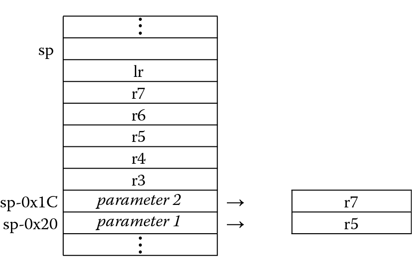
The stack structure is drawn in Figure 13.6. The two parameters are pushed to the bottom of the stack, and then the saved registers are stacked on top of them, ending with the Link Register at the top. Since register r13 now points to the top of the stack, it’s necessary to use the stack pointer with a negative offset to address the parameters. When the result is computed, it must be stored back to the bottom of the stack, again using the stack pointer with a negative offset.
If the example above used full descending stacks, then the PUSH and POP instructions could be used just as easily. To see how this might look using a Cortex-M4, let’s examine the same algorithm that uses full descending stacks.
Example 13.7
Since the object of the example is to compare the stack structures rather than the algorithm itself, the following code shows how to push two values onto the stack, call the subroutine, and then pop two values off the stack. Careful readers will have noticed that if the shift value were fixed, rather than variable as it is in our subroutine, you could save quite a bit of coding by just using the SSAT instruction that we saw in Chapter 7. For this example, the SRAM block begins at address 0x20000000 on the Tiva TM4C123GH6ZRB.
SRAM_BASE EQU 0x20000200
LDR sp, =SRAM_BASE ; stack pointer initialized
; try out a positive case (this should saturate)
MOV r1, #0x40000000
MOV r2, #2
PUSH {r1,r2} ; push parameters on the stack
BL saturate
; pop results off the stack
; now r1 = result of shift
POP {r1,r2}
; try out a negative case (should not saturate)
MOV r1, #0xFFFFFFFE
MOV r2, #8
PUSH {r1,r2}
BL saturate
POP {r1,r2}
stop
B stop
saturate
; Subroutine saturate32
; Parameters are read from the stack, and
; registers r4 through r7 are saved on the stack.
; The result is placed at the bottom of the stack.
; Registers used:
; r4 - result
; r5 - operand to be shifted
; r6 - scratch register
; r7 - shift amount (m)
; r4 = saturate32(r5 << m)
PUSH {r4-r7,lr} ; save off used registers
LDR r5, [sp, #0x14] ; get first parameter off stack
LDR r7, [sp, #0x18] ; get second parameter off stack
MOV r6, #0x7FFFFFFF
MOV r4, r5, LSL r7
ASR r4, r7
TEQ r5, r4 ; if (r5! = (r4 > >m))
IT NE
EORNE r4, r6, r5, ASR #31 ; r4 = 0x7FFFFFFF^sign(r5)
STR r4, [sp, #0x14] ; move result to bottom of stack
POP {r4-r7,pc} ; return
Notice at the end of the subroutine that the Link Register value that was pushed onto the stack is now loaded into the Program Counter using the POP instruction, similar to the method used by the ARM7TDMI.
13.5 The ARM APCS
It turns out that there’s a standard called the ARM Application Procedure Call Standard (AAPCS) for the ARM architecture, which is part of the Application Binary Interface (ABI) (ARM 2007b). The AAPCS defines how subroutines can be separately written, separately compiled, and separately assembled to work together. It describes a contract between a calling routine and a called routine that defines:
- Obligations on the caller to create a program state in which the called routine may start to execute
- Obligations on the called routine to preserve the program state of the caller across the call
- The rights of the called routine to alter the program state of its caller
The standard is also designed to combine the ease, speed, and efficiency of passing parameters through registers with the flexibility and extensibility of passing in the stack. While the document describes procedures for writing code, it also defines the use of registers, shown in Figure 13.7. Some parts of the specification include the following:
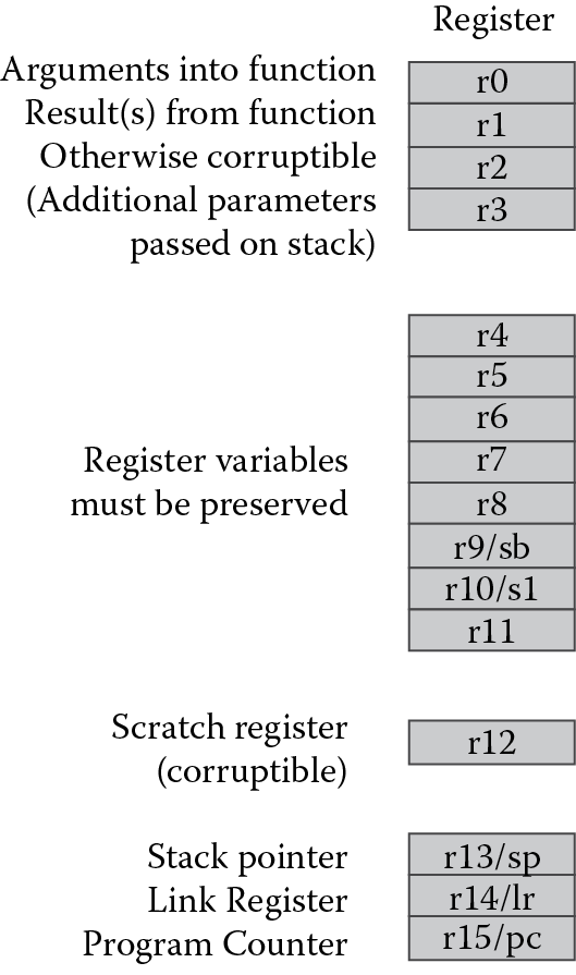
The first four registers r0-r3 (also called a1-a4, for argument) are used to pass argument values into a subroutine and to return a result value from a function. They may also be used to hold intermediate values within a routine (but in general, only between subroutine calls).
Register r12 (IP) may be used by a linker as a scratch register between a routine and any subroutine it calls. It can also be used within a routine to hold intermediate values between subroutine calls.
Typically, the registers r4-r8, r10, and r11 are used to hold the values of a routine’s local variables. Of these, only r4-r7 can be used uniformly by the whole Thumb instruction set, but the AAPCS does not require that Thumb code only use those registers.
A subroutine must preserve the contents of the registers r4-r8, r10, r11, and SP (and r9 in some Procedure Call Standard variants).
Stacks must be eight-byte aligned, and the ARM and Thumb C and C++ compilers always use a full descending stack.
For floating-point operations, similar rules apply. According to the standard, registers s16-s31 must be preserved across subroutine calls; registers s0-s15 do not need to be preserved, so you could use these for passing arguments to a subroutine. The only status register that may be accessed by conforming code is the FPSCR, and within this register, certain bits must be left unchanged. While it’s important to write code that conforms to the specification, beginning programmers would do well to practice with the specification in mind, and as time permits, rework your code to follow the standard.
Example 13.8
Let’s look at a short floating-point routine for the Cortex-M4 that uses a Taylor series expansion to compute the value of sin(x). The subroutine uses registers s0-s10, so no floating-point registers need to be stacked. The input to the routine and the final result are stored in register s0. As we saw in Chapter 7, sometimes divisions can be avoided entirely by calculating constants beforehand and using multiplication operations instead.
;************************************************************
;
; This is the code that gets called when the processor first starts execution
; following a reset event.
;
;************************************************************
EXPORT Reset_Handler
ENTRY
Reset_Handler
; Enable the FPU
; Code taken from ARM website
; CPACR is located at address 0xE000ED88
LDR.W r0, =0xE000ED88
LDR r1, [r0] ; Read CPACR
; Set bits 20-23 to enable CP10 and CP11 coprocessors
ORR r1, r1, #(0xF << 20)
; Write back the modified value to the CPACR
STR r1, [r0] ; wait for store to complete
DSB
; Reset pipeline now that the FPU is enabled
ISB
;
; The calculation of the sin(x) will be done in the
; subroutine SinCalc. The AAPCS dictates the first
; 16 FPU registers (s0-s15) are not preserved, so we will
; use them in the calling routine to pass the operand and
; return the result. Registers s16-s31 must be preserved in
; a subroutine, so they are used in the calling routine.
; FPU registers
; s0 - Passed operand and returned result
; Evaluate the function for operand the test operand
VLDR.F32 s0, = 1.04719
BL SinCalc
Exit B Exit
; Sine code
; The algorithm is a Taylor series with
; 4 terms (x = x - x^3/3! + x^5/5! - x^7/7!)
; Optimized, we have 9 multiplications and 3 adds.
; We can avoid the divisions by computing 1/3!, 1/5!, etc. and
; using the constant in a multiplication.
;
; This formula works for all x in the range [0, pi/2]
; [0, pi/2]
;
; This routine assumes AAPCS -
; regs s0-s15 parameters and/or scratch
; Register usage:
; s0 - input operand and return result
; s1 - 1/3! (invfact3)
; s2 - 1/5! (invfact5)
; s3 - 1/7! (invfact7)
; s4 - x * s1 (xdiv3), then s4 * s7 (x^2 * xdiv3) (x3div3)
; s5 - x * s2 (xdiv5), then s5 * s8 (x^4 * xdiv5) (x5div5)
; s6 - x * s3 (xdiv7), then s6 * s9 (x^6 * xdiv7) (x7div7)
; s7 - x^2
; s8 - x^4
; s9 - x^6
; s10 - scratch
SinCalc
; set up the three inverse factorial constants
VLDR.F32 s1, invfact3
VLDR.F32 s2, invfact5
VLDR.F32 s3, invfact7
;
VMUL.F32 s4, s0, s1 ; compute xdiv3
VMUL.F32 s7, s0, s0 ; compute x^2
VMUL.F32 s5, s0, s2 ; compute xdiv5
VMUL.F32 s4, s4, s7 ; compute x3div3
VMUL.F32 s8, s7, s7 ; compute x^4
VMUL.F32 s6, s0, s3 ; compute xdiv7
VSUB.F32 s10, s0, s4 ; compute terms12, x-x^3/3!
VMUL.F32 s9, s7, s8 ; compute x^6
VMUL.F32 s5, s5, s8 ; compute x5div5
VMUL.F32 s6, s6, s9 ; compute x7div7
VADD.F32 s10, s10, s5 ; compute terms123, x-x^3/3! + x^5/5!
VSUB.F32 s0, s10, s6 ; compute result
BX lr ; return
invfact3 DCD 0x3E2AAAAB ; 1/3!
invfact5 DCD 0x3C088888 ; 1/5!
invfact7 DCD 0x39500CD1 ; 1/7!
13.6 Exercises
- What’s wrong with the following ARM7TDMI instructions?
- STMIA r5!, {r5, r4, r9}
- LDMDA r2, {}
- STMDB r15!, {r0-r3, r4, lr}
- On the ARM7TDMI, if register r6 holds the address 0x8000 and you executed the instruction
STMIA r6, {r7, r4, r0, lr} - what address now holds the value in register r0? Register r4? Register r7? The Link Register?
- Assume that memory and ARM7TDMI registers r0 through r3 appear as follows:
Address
Register
0x8010
0x00000001
0x13
r0
0x800C
0xFEEDDEAF
0xFFFFFFFF
r1
0x8008
0x00008888
0xEEEEEEEE
r2
0x8004
0x12340000
0x8000
r3
0x8000
0xBABE0000
- Describe the memory and register contents after executing the instruction
LDMIA r3!, {r0, r1, r2} - Suppose that a stack appears as shown in the first diagram below. Give the instruction or instructions that would push or pop data so that memory appears in the order shown. In other words, what instruction would be necessary to go from the original state to that shown in (a), and then (b), and then (c)?
|
Address |
||||
|
0x8010 |
0x00000001 |
0x00000001 |
0x00000001 |
0x00000001 |
|
0x800C |
0xFEEDDEAF |
0xFEEDDEAF |
0xFEEDDEAF |
0xFEEDDEAF |
|
0x8008 |
|
0xBABE2222 |
0xBABE2222 |
|
|
0x8004 |
|
|
0x12340000 |
|
|
0x8000 |
|
|
|
|
|
Original |
(a) |
(b) |
(c) |
- Convert the cosine table from Problem 1 in Chapter 12 into a subroutine, using a full descending stack.
- Rewrite Example 13.4 using full descending stacks.
- Rewrite Example 13.5 using full descending stacks.
- Rewrite Example 13.6 using full descending stacks.
- Convert the factorial program written in Chapter 3 into a subroutine, using full descending stacks. Pass arguments to the subroutine using both pass-by-register and pass-by-stack techniques.
- Write the ARM7TDMI division routine from Chapter 7 as a subroutine that uses empty ascending stacks. Pass the subroutine arguments using registers, and test the code by dividing 4000 by 32.
- Match the following terms with their definitions:
- Recursive 1. Subroutine can be interrupted and called by the interrupting routine
- Relocatable 2. A subroutine that calls itself
- Position 3. The subroutine can be placed anywhere in memory independent
- Reentrant 4. All program addresses are calculated relative to the Program Counter
- Write the ARM7TDMI division routine from Chapter 7 as a subroutine that uses full descending stacks. Pass the subroutine arguments using the stack, and test the code by dividing 142 by 7.
- Write ARM assembly to implement a PUSH operation without using LDM or STM instructions. The routine should handle three data types, where register r0 contains 1 for byte values, 2 for halfword values, and 4 for word values. Register r1 should contain the data to be stored on the stack. The stack pointer should be updated at the end of the operation.
- Write ARM assembly to check whether an N × N matrix is a magic square. A magic square is an N × N matrix in which the sums of all rows, columns, and the two diagonals add up to N(N2 + 1)/2. All matrix entries are unique numbers from 1 to N2. Register r1 will hold N. The matrix starts at location 0x4000 and ends at location (0x4000 + N2). Suppose you wanted to test a famous example of a magic square:
16
3
2
13
5
10
11
8
9
6
7
12
4
15
14
1
- The numbers 16, 3, 2, and 13 would be stored at addresses 0x4000 to 0x4003, respectively. The numbers 5, 10, 11, and 8 would be stored at addresses 0x4004 to 0x4007, etc. Assume all numbers are bytes. If the matrix is a magic square, register r9 will be set upon completion; otherwise it will be cleared. You can find other magic square examples, such as Ben Franklin’s own 8 × 8 magic square, on the Internet to test your program.
- Another common operation in signal processing and control applications is to compute a dot product, given as
- where the dot product a is a sum of products. The coefficients cm and the input samples xm are stored as arrays in memory. Assume sample data and coefficients are 16-bit, unsigned integers. Write the assembly code to compute a dot product for 20 samples. This will allow you to use the LDM instruction to load registers with coefficients and data efficiently. You probably want to bring in four or five values at a time, looping as needed to exhaust all values. Leave the dot product in a register, and give the register the name DPROD using the RN directive in your code. If you use the newer v7-M SIMD instructions, note that you can perform two multiples on 16-bit values at the same time.
- Suppose your stack was defined to be between addresses 0x40000000 and 0x40000200, with program variables located at address 0x40000204 and higher in memory, and your stack pointer contains the address 0x400001FC. What do you think would happen if you attempt to store 8 words of data on an ascending stack?