Table of Contents for
ARM Assembly Language, 2nd Edition
 ARM Assembly Language, 2nd Edition
Published by
Chapman and Hall/CRC, 2016
ARM Assembly Language, 2nd Edition
Published by
Chapman and Hall/CRC, 2016
- Contents
- ARM Assembly Language: Fundamentals and Techniques, Second Edition
- Preliminaries
- To our families
- Preface
- Acknowledgments
- Authors
- Chapter 1 - An Overview of Computing Systems
- Chapter 2 - The Programmer’s Model
- Chapter 3 - Introduction to Instruction Sets: v4T and v7-M
- Chapter 4 - Assembler Rules and Directives
- Chapter 5 - Loads, Stores, and Addressing
- Chapter 6 - Constants and Literal Pools
- Chapter 7 - Integer Logic and Arithmetic
- Chapter 8 - Branches and Loops
- Chapter 9 - Introduction to Floating-Point: Basics, Data Types, and Data Transfer
- Chapter 10 - Introduction to Floating-Point: Rounding and Exceptions
- Chapter 11 - Floating-Point Data-Processing Instructions
- Chapter 12 - Tables
- Chapter 13 - Subroutines and Stacks
- Chapter 14 - Exception Handling: ARM7TDMI
- Chapter 15 - Exception Handling: v7-M
- Chapter 16 - Memory-Mapped Peripherals
- Chapter 17 - ARM, Thumb and Thumb-2 Instructions
- Chapter 18 - Mixing C and Assembly
- Appendix A: Running Code Composer Studio
- Appendix B: Running Keil Tools
- Appendix C: ASCII Character Codes
- Appendix D
- Glossary
- References
Chapter 14
Exception Handling
ARM7TDMI
14.1 Introduction
Large applications, including operating systems, often have to deal with inputs from various sources, such as keyboards, mice, USB ports, and even power management blocks telling the processor its battery is about to run dry. Sometimes an embedded microcontroller has only one or two external input sources (e.g., from sensors in an engine), but it may still have peripheral devices that may need attention from time to time, such as a watchdog timer. Universal asynchronous receiver/transmitters (UARTs), wake-up alerts, analog-to-digital converters (ADCs), and I2C devices can all demand the processor’s time. In the next two chapters, we’re going to examine the different types of exceptions a processor can face in light of the fact that they are not isolated, only running code and talking to no one. In our definition of an exception, the events that can cause one must not be immediately thought of as bad or unwanted. Exceptions include benign events like an interrupt, and this can be any kind of interrupt, like someone moving a mouse or pushing a button. Technically, anything that breaks a program’s normal flow could be considered an exception, but it’s worth detailing the different types, since some can be readily handled and others are unexpected and can cause problems. At this end of the spectrum, catastrophic faults, such as a bus error when trying to fetch an instruction, may have no solution in software and the best outcome may be to alert the user before halting the entire system. Certain events can lead to a serious system failure, and while they are rare, they should be anticipated to help find the cause of the problem during application development or to plan for a graceful shutdown. For example, a rogue instruction in the processor’s pipeline or a memory access to an address that doesn’t exist should not occur once the software is finished and tested. Version 4T cores and version 7-M cores handle exceptions differently, and we’ll therefore examine the exception model for the Cortex-M4 in Chapter 15. In this chapter, we’ll start with the exception model for the ARM7TDMI, and we’ll examine exceptions in two large classes—interrupts and error conditions.
14.2 Interrupts
Interrupts are very common in microprocessor systems. They provide the ability for a device such as a timer or a USB interface to poke the processor in the ribs and loudly announce that it wants attention. Historically, large computers only took a set of instructions and some data, calculated an answer, and then stopped. These machines had no worries about dozens of interfaces and devices all vying for part of the CPU’s time. Once microprocessors became ubiquitous in electronic devices, they had to deal with supporting an operating system and application software in addition to calculating and moving data for other parts of a system. Microcontrollers are, in effect, smaller versions of complete systems, where motor controllers, timers, real-time clocks, and serial interfaces all demand some face time from the processor. So what’s the best way to let the processor do its main tasks while allowing other peripherals to ask for assistance every so often?
Say you had a UART, which is a type of serial interface, attached to a processor that received a character from another device, say a wireless keyboard. When a character shows up in the UART, it’s basically sitting at a memory location assigned to the UART waiting for the processor to get the data. There are roughly three ways the processor can handle this situation. The first, and by far the least efficient, is for the processor to sit in a loop doing absolutely nothing except waiting for the character to show up. Given the speed at which processors run, where billions of instructions can now be processed in a single second, waiting even 1/100th of a second for a device to transmit the data wastes millions of cycles of bandwidth. The second option is for the processor to occasionally check the memory location to see if there is some new data there, known as polling. While the processor can do other things while it waits, it still has to take time to examine the (possibly empty) memory location. The third option, and clearly the best one, is to have the device tell the processor when there is new data waiting for it. This way, the processor can spend its time performing other functions, such as updating a display or converting MP3 data to an analog waveform, while it waits for a slower device to complete its task. An interrupt is therefore an efficient method for telling the processor that something (usually a device or peripheral) needs attention. If you refer back to the diagram of the ARM7TDMI in Chapter 1 (Figure 1.4), you will notice two external lines coming into the part—nIRQ and nFIQ, where the “n” denotes an active low signal. These are the two interrupt lines going into the processor, with a low priority interrupt called IRQ and a high priority interrupt called FIQ. In addition to hardware interrupts, software has one as well, called aptly enough, Software Interrupt or SWI in the older notation, and SVC in the newer notation. We will look at all of these in detail to see how they work.
14.3 Error Conditions
While you hope not to have these exceptions in a system, they do occur often enough that software needs to be sufficiently robust to handle them. The ARM cores recognize a few error conditions, some of which are easy to handle, some of which are not. An undefined instruction in the program can cause an error, but this may or may not be intentional. In a completely tested system where no new code is introduced (e.g., an embedded processor in an MP3 player that only handles the display), one would not expect to see a strange instruction suddenly show up in the application code. However, if you know that you have a design that requires floating-point operations, but the processor does not support floating-point in hardware, you could decide to use floating-point instructions and emulate them in software. Once the processor sees floating-point instructions (which aren’t listed in this book but can be found in the ARM Architectural Reference Manual (ARM 2007c)), it will take an undefined instruction exception since there is no hardware to perform the operations. The processor can then take the necessary actions to perform the operations anyway, using only software to emulate the floating-point operation, appearing to the user as if floating-point hardware were present.
Data and prefetch aborts are the exception types that often cause programmers the most angst. A prefetch abort occurs when the processor attempts to grab an instruction in memory but something goes wrong—if memory doesn’t exist or the address is outside of a defined memory area, the processor should normally be programmed to recover from this. If the address is not “expected” but still permitted, then the processor may have additional hardware (known as a memory management unit or MMU) to help it out, but this topic is outside the scope of this book. A data abort occurs when the processor attempts to grab data in memory and something goes wrong (e.g., the processor is in an unprivileged mode and the memory is marked as being readable only in a privileged mode). Certain memory regions may be configured as being readable but not writable, and an attempt to write to such a region can cause a data abort. As with prefetch aborts, the processor usually needs to be able to recover from some situations and often has hardware to assist in the recovery. We will see more about aborts in Section 14.8.4.
14.4 Processor Exception Sequence
When an exception occurs, the ARM7TDMI processor has a defined sequence of events to start the handling and recovery of the exception. In all cases except a reset exception, the current instruction is allowed to complete. Afterward, the following sequence begins automatically:
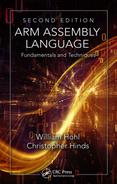
- The CPSR is copied into SPSR_<mode>, where <mode> is the new mode into which the processor is about to change. Recall from Chapter 2 that the register file contains SPSR registers for exceptional modes, shown in Figure 14.1.
- The appropriate CPSR bits are set. The core will switch to ARM state if it was in Thumb state, as certain instructions do not exist in Thumb that are needed to access the status registers. The core will also change to the new exception mode, setting the least significant 5 bits in the CPSR register. IRQ interrupts are also disabled automatically on entry to all exceptions. FIQ interrupts are disabled on entry to reset and FIQ exceptions.
- The return address is stored in LR_<mode>, where <mode> is the new exception mode.
- The Program Counter changes to the appropriate vector address in memory.
Note that the processor is responsible for the above actions—no code needs to be written. At this point, the processor begins executing code from an exception handler, which is a block of code written specifically to deal with the various exceptions. We’ll look at how handlers are written and what’s done in them shortly. Once the handler completes, the processor should then return to the main code—whether or not it returns to the instruction that caused the exception depends on the type of exception. The handler may restore the Program Counter to the address of the instruction after the one that caused the exception. Either way, the last two things that remain to be done, and must be done by the software handler, are
- The CPSR must be restored from SPSR_<mode>, where <mode> is the exception mode in which the processor currently operates.
- The PC must be restored from LR_<mode>.
These actions can only be done in ARM state, and fortunately, the software can usually do these two operations with a single instruction at the end of the handler.
It is worth noting at this point that while most ARM cores have similar exception handling sequences, there are some differences in the newest cores (e.g., the Cortex-M3/M4 has a different programmer’s model, and the Cortex-A15 has even more exception types and modes). The Technical Reference Manuals for the individual cores contain complete descriptions of exception sequences, so future projects using version 7 and version 8 processors might require a little reading first.
14.5 The Vector Table
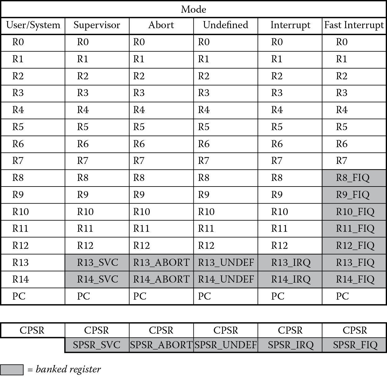
Earlier in Section 2.3.3, we saw the exception vector table for the first time, but we didn’t do much with it. At this point, we can start using these addresses to handle the various types of exceptions covered in this chapter. Figure 14.2 shows the table again, with the vectors listed as they would be seen in memory. Recall that while some processors, e.g., the 6502 and Freescale’s 680x0 families, put addresses in their vector tables, ARM uses actual instructions, so the reset exception vector (at address 0x0) would have a change-of-flow instruction of some type sitting there. It may not be the actual instruction B, as we’ll see in a moment.
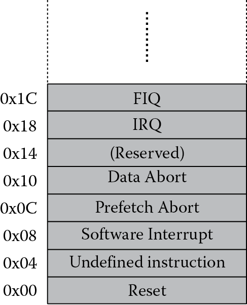
Having covered literal pools, we can now begin to examine the way that real ARM code would be written and stored in memory with regard to exceptions. Figure 14.3 shows a memory map from address 0x0 to 0xFFFFFFFF and an example layout for the exception handlers. Note that this is only an example, and may not be applicable to your application, so these are just options. For each type of exception, there is usually a dedicated block of code, called an exception handler, that is responsible for acknowledging an exceptional condition and, more often than not, fixing it. Afterward, the code should return the processor back to the point from where it left, now able to continue without the exception. Not all exceptions need handlers, and in some deeply embedded systems, the processor may not be able to recover. Consider the hypothetical situation where the processor tries to read a memory location that is not physically present. Further suppose that an address in the memory map does not point to a memory chip or memory block but rather points to nothing. The machine may be programmed to reset itself if something like that ever happens. Larger applications, such as a cell phone, will have to deal with all exceptions and provide robust methods to recover from them, especially in light of having hardware that can change, e.g., if a memory card can be added or removed.
Since exception vectors contain instructions at their respective addresses in memory, an exception such as an IRQ, which is a low-priority interrupt, would have some kind of change-of-flow instruction in its exception vector to force the processor to begin fetching instructions from its handler. These change-of-flow instructions are one of the following:
- Branch instruction—A direct branch can be used to jump to your exception handler; however, the range of a B instruction is only 32 MB, and this may not always work with every memory organization. If your exception handler is more than 32 MB away, you must use another type of instruction.
- MOV instruction—A MOV instruction can change the PC simply by loading the register with a value. The value loaded could be created from a byte rotated by an even number of bits, so that it fits within a 32-bit instruction, for example,
MOV PC, #0xEF000000
Notice also that this instruction contains a 32-bit address, but it can be constructed using the rotation scheme discussed in Chapter 6.
- LDR instruction—Recall that data can be stored in instruction memory and then accessed by using an offset to the Program Counter, as we saw in Chapter 6 with literals. The instruction would have the form
LDR PC, [PC + offset]
- where the offset would be calculated using the address of the handler, the vector address, and the effects of the pipeline.
Looking at our example memory map in Figure 14.3, we see that the reset exception can use a simple branch (B) instruction, provided that we place the reset handler within a 32 MB range. The next exception, the undefined instruction exception, uses a load instruction with an offset to access the value sitting at address 0xFFC in memory. When the processor is executing the load instruction at address 0x4, the Program Counter contains the value 0xC, since it is the address of the instruction being fetched. The offset would then be 0xFF0. When the value at address 0xFFC, 0x30008000, is loaded into the Program Counter, it has the same effect as jumping there with a branch instruction. One other thing to note is the size of the offset used—there are only 12 bits to create an offset with a load instruction of this type; hence, the value 0xFFC is the last word that could be accessed within that 4 KB range. The next word has the address 0x1000 and is too far away.
Continuing up the table, we come to the SWI (or SVC, as it is now known) exception. This example shows that an address like 0x30000000 can be generated using the byte rotation scheme and therefore can be reached using a simple MOV instruction. The SVC handler is then placed at that location in memory. Skipping the two abort exceptions and the reserved vector, we continue to address 0x18, where the IRQ exception vector contains a simple branch instruction, and the IRQ handler starts at an address that is located within 32 MB of the branch.
The last exception vector, to which we alluded back in Chapter 2, sits at the top of the vector table for a reason. FIQ interrupts are fast interrupts, meaning that if you have a critical event that must be serviced immediately, and it holds the highest priority among interrupts, then you want to spend as little time as possible getting to the code to service it. We also know from Chapter 8 that branches cause a pipelined architecture to throw away instructions, so rather than cause the processor to take some type of branch to get to the handler, the FIQ vector is the first instruction of the handler! There is no need to branch, since the Program Counter will be set to the address 0x1C when the processor acknowledges and begins to service the interrupt. The FIQ handler is then executed as the Program Counter increments through memory.
14.6 Exception Handlers
Exceptions require some housekeeping. Normally, the processor is busy moving data or crunching numbers, but when an exception occurs, processors have to prepare to save the status of the machine, since at some point they must return to crunching numbers or moving data. When an exceptional condition is seen by the processor, the first thing it must do is copy the Current Program Status Register into a Saved Program Status Register, and in particular the SPSR belonging to the new mode associated with the exception. Recall that for five of the seven modes, there are unique SPSRs (e.g., Abort Mode has an SPSR_abort). The Current Program Status Register must then be changed to reflect what happened—the mode bits will be changed, further interrupts may be disabled, and the state will change from Thumb state to ARM state if the processor was executing Thumb instructions (there’s more on Thumb in Chapter 17). Since exceptions cause the code to jump to a new location in memory, it’s imperative to save off a return address, akin to what was done for subroutines, so that the processor can return later. This return address is stored in the Link Register associated with the exception type (e.g., R14_FIQ if the processor took an FIQ exception). The Program Counter is then changed to the appropriate vector address. All of this work is done by the processor, so the focus for the programmer is to write the appropriate exception handler.
Once the mode of the processor has been changed, the exception handler will have to access its own stack pointer (R13_FIQ, for example), its own Link Register, and its own Saved Program Status Register. There are general-purpose registers that can be used by the handler, but normally some of these are saved off to a stack before using them, since any registers that are corrupted by a handler must be restored before returning (refer back to the ARM Application Procedure Call Standard that we saw in Chapter 13). This whole process of storing registers to external memory takes time, and again, depending on the type of exception, may cause an unacceptable delay in processing an exception. Going back to the idea of a fast interrupt, we’ve already seen that the FIQ vector sits at the top of the vector table, saving a branch instruction. To prevent having to store data on the stack before handling the FIQ interrupts, there are also five additional general-purpose registers (R8_FIQ to R12_FIQ) that the handler can access.
Exception handlers can be intentionally short, or long, robust routines depending on how much needs to be done for any given exception. In Section 14.8.2, we’ll examine an undefined exception handler of only a few lines. At the end of all handlers, the programmer is responsible for restoring the state of the machine and returning back to the original instruction stream before the exception. This can be done as an atomic operation, moving the contents of the SPSR back into the CPSR while moving the Link Register into the Program Counter. The instructions to do these operations only exist in the ARM instruction set, which was why the processor had to switch from Thumb to ARM if it was executing Thumb code. The various return methods are discussed more in the next few sections.
14.7 Exception Priorities
Exceptions must be prioritized in the event that multiple exceptions happen at the same time. Consider the case where a peripheral on a microcontroller has generated a low-priority interrupt, say an A/D converter has finished sampling some data and alerts the processor by pulling on the IRQ line. At the exact same time, the processor tries to access a memory location that is undefined while another high-priority interrupt tries to tell the processor that we’re about to lose power in two minutes. The processor must now decide which exception type gets handled first. Table 14.1 shows the exception types in order of their priority.
ARM7TDMI Exception Priorities
Priority
Exception
Comment
Highest
Reset
Handler usually branches straight to the main routine.
Data Abort
Can sometimes be helped with hardware (MMU).
FIQ
Current instruction completes, then the interrupt is acknowledged.
IRQ
Current instruction completes, then the interrupt is acknowledged. Used more often than FIQ.
Prefetch Abort
Can sometimes be helped with hardware (MMU).
SVC
Execution of the instruction causes the exception.
Lowest
Undefined Instruction
SVC and Undef are actually mutually exclusive, so they have the same priority.
For complicated reasons, data aborts are given the highest priority apart from the reset exception, since if they weren’t, there would be cases where if two or more exceptions occurred simultaneously, an abort could go undetected. If an FIQ and an IRQ interrupt occur at the same time, the FIQ interrupt handler goes first, and afterward, the IRQ will still be pending, so the processor should still be able to service it. An SVC and an Undefined Instruction exception are mutually exclusive, since an SVC instruction is defined and cannot generate an Undefined Instruction exception. To settle the contention described earlier, the Data Abort exception would be handled first, followed by the FIQ interrupt alerting the system to a power failure, and then the A/D converter will have its turn.
A situation could present itself where the processor is already handling an exception and another exception occurs. For example, suppose the processor is working on an FIQ interrupt and has already begun executing the handler for it. During the course of executing this code, a data abort occurs—one that could be helped by additional MMU hardware. The processor would begin exception processing again, storing the CPSR into the register SPSR_abort, changing the mode, etc., and then jump to the new exception handler. Once the second exception completes and the Program Counter points back to the first handler, the original FIQ exception can finish up. If another FIQ interrupt tried to interrupt instead of a data abort, it would be blocked, because FIQ interrupts are automatically disabled by the processor upon entry to FIQ mode. The software could enable them again, but this is not typical practice.
14.8 Procedures for Handling Exceptions
As mentioned before, sometimes handlers can be very short and sometimes they can be quite complicated—it all depends on what the handler is responsible for doing. In this next section, we’ll examine the basic requirements for the different exception types, along with some detailed code examples using the STR910FM32 and LPC2132 microcontrollers included in the Keil simulation tools.
14.8.1 Reset Exceptions
When the processor first receives power, it will put the value 0x00000000 on the 32-bit address bus going to memory and receive its first instruction, usually a branch. This branch then takes it to the first instruction of the reset handler, where initialization of the processor or microcontroller is started. Depending on what’s needed, a reset handler can be very simple, or it may need to perform tasks such as:
- Set up exception vectors
- Initialize the memory system (e.g., if a memory management unit [MMU] or memory protection unit [MPU] is present)
- Initialize all required processor mode stacks and registers
- Initialize any critical I/O devices
- Initialize any peripheral registers, control registers, or clocks, such as a phase-locked loop (PLL)
- Enable interrupts
- Change processor mode and/or state
We’ll see in the example shortly how registers are configured and how interrupts are handled. Once the handler sets up needed registers and peripherals, it will jump to the main routine in memory. Reset handlers do not have a return sequence at the end of the code.
14.8.2 Undefined Instructions
We saw in Chapter 3 that the ARM7TDMI has about 50 instructions in its instruction set, plus all of the combinations of addressing modes and registers. With exactly 232 possible instruction bit patterns, that leaves quite a few combinations of ones and zeros that are classified as an undefined instruction! An exception can occur if the processor doesn’t recognize a bit pattern in memory, but it can also take an Undefined exception in two other cases. The first is if the processor encounters an instruction that is intended for a coprocessor (such as a floating-point unit or other special bit of hardware that was attached to the ARM7TDMI’s coprocessor interface), but the coprocessor either doesn’t exist or it doesn’t respond. This first case was mentioned in Section 14.3, where the processor can emulate floating-point instructions by building a very smart exception handler that goes into the instruction memory and examines the offending instruction. If it turns out to be one of the instructions that the software wishes to support (e.g., a floating-point addition), then it begins to decode it. Software determines the operation that is needed, which would have to use integer registers and an integer datapath to perform the operation, and then calculates the result using a floating-point format. We then return to the main routine again. Theoretically, it allows software to be written only once using real floating-point instructions, and this could save money and power if speed isn’t critical. Should a hardware floating-point unit be present (maybe a silicon vendor makes two slightly different models of microcontroller or SoC), the code will execute more quickly in hardware.
The second case that can generate an undefined instruction exception involves a coprocessor not responding to an instruction. As an example, Vector Floating-Point (VFP) coprocessors appear on some of the more advanced ARM cores, such as the Cortex-A8 and ARM1136JF-S. They have unique instructions, such as FDIVS and FSQRTS, and the ability to generate errors just like the main integer processor. However, if the VFP coprocessor generates an exception while processing one of its own instructions (suppose it tried to divide by zero), it will simply not respond when the integer processor tries to give it another instruction. The exception handler will then have to determine that the VFP coprocessor generated an exception on the last instruction that it accepted.
The last case that will generate an exception is when the processor sees a legitimate coprocessor instruction but is not in a privileged mode. For example, on most advanced applications processors, such as the ARM926EJ-S, ARM1136JF-S, or Cortex-A15, caches are included to improve performance (think of a cache as a small block of memory used to hold instructions and data so that the processor doesn’t have to go to external memory as often). Caches always have a cache control register to set things up, and ARM uses Coprocessor 15, or CP15, to do this. While there isn’t a real coprocessor in hardware, the instructions can be used anyway—have a look at the STC (Store Coprocessor) instruction and notice that bits 8 through 11 designate a coprocessor number. Coprocessor 15 is reserved for cache and MMU control registers. Meddling with these registers is only allowed if you’re in a privileged mode, so a user’s code would not be allowed to change the hardware configurations. The processor would reject the offending instruction by taking an Undefined Instruction exception.
Example 14.1
Let’s examine a simple bit of code, running on an LPC2132 microcontroller from NXP, that forces an Undefined Instruction exception. In order to demonstrate how the processor behaves during such an exception, we’ll use a contrived situation where we wish to allow an instruction, normally undefined, to be emulated in software. This is analogous to floating-point emulation mentioned earlier, except our handler will be very short and very clumsy. Suppose that we call our instruction ADDSHFT. It takes one argument—the contents of register Rm, which can range from r0 to r7—and adds the contents of register r0 to it, shifting the result left by 5 bits. The assembler certainly wouldn’t recognize the mnemonic, so we will call the instruction manually using DCD statements. When the processor fetches the word of data in memory, it proceeds through the pipeline as an instruction. Once the processor tries to execute our new bit pattern, it will take an Undefined Instruction exception, where our handler will decode the instruction and perform the operation.
There are a few things to observe in the example. The first is which operations the processor does for us, and which operations must be done by a programmer. Recall the switching the mode is normally done by the processor during an exceptional condition; however, as we’ll see shortly, the programmer can also manually change the mode to set up a stack pointer. On the ARM7TDMI, saving registers and state information to the stack must be done by the programmer. The second thing to observe is the register file. Since the machine will change to Undef mode, we will be using a new register r13 and r14, so when you simulate this program, be sure to note the values in all of the registers in the processor, since we will now be working with more than just the traditional r0 through r15 in a single mode.
Below, you can see the complete code listing:
; Area Definition and Entry Point
SRAM_BASE EQU 0x40000000 ; start of RAM on LPC2132
Mode_UND EQU 0x1B
Mode_SVC EQU 0x13
I_Bit EQU 0x80
F_Bit EQU 0x40
AREA Reset, CODE, READONLY
ARM
ENTRY
; Exception Vectors
; Dummy Handlers are implemented as infinite loops which can be modified.
Vectors LDR PC, Reset_Addr
LDR PC, Undef_Addr
LDR PC, SVC_Addr
LDR PC, PAbt_Addr
LDR PC, DAbt_Addr
NOP ; Reserved Vector
LDR PC, IRQ_Addr
LDR PC, FIQ_Addr
Reset_Addr DCD Reset_Handler
Undef_Addr DCD UndefHandler
SVC_Addr DCD SVCHandler
PAbt_Addr DCD PAbtHandler
DAbt_Addr DCD DAbtHandler
DCD 0 ; Reserved Address
IRQ_Addr DCD IRQHandler
FIQ_Addr DCD FIQHandler
SVCHandler B SVCHandler
PAbtHandler B PAbtHandler
DAbtHandler B DAbtHandler
IRQHandler B IRQHandler
FIQHandler B FIQHandler
; Reset Handler
; Undefined Instruction test
; 31 30 29 28 27 26 25 24 23 22 21 20 19 18 17 16 15 14 13 12 11 10 9 8 7 6 5 4 3 2 1 0
; |0 1 1 1 |0 1 1 1 |1 1 1 1 |0 0 0 0 |0 0 0 0 |1 1 1 1 1 1 1 1| Rm |
;|CC = AL | OP | Rn = 0 | Rd = 0 | Rm |
Reset_Handler
; The first order of business is to set up a stack pointer in
; UNDEF mode, since we know our simulation will hit an undefined
; instruction.
MSR CPSR_c, #Mode_UND:OR:I_Bit:OR:F_Bit
LDR sp, = SRAM_BASE + 80; initialize stack pointer
; switch back to Supervisor mode
MSR CPSR_c, #Mode_SVC:OR:I_Bit:OR:F_Bit
MOV r0, #124; put some test data into r0
MOV r4, #0x8B; put some test data into r4
ADDSHFTr0r0r4 DCD 0x77F00FF4; r0 = (r0 + r4) LSL #5
NOP
Loop B Loop
NOP
;/******************************************************************/
;/* Undefined Handler*/
;/******************************************************************/
; Note that this handler is NOT AAPCS compliant. See the
; RealView Compilation Tools Developer Guide for examples of
; AAPCS-compliant handlers, specifically for maintaining 8-byte
; alignment and stack requirements. We’re taking some shortcuts
; here just so we can concentrate on a simple mechanism to deal
; with an undefined instruction.
UndefHandler
STMFD sp!, {r0-r12, LR} ; Save Workspace & LR to Stack
MRS r0, SPSR ; Copy SPSR to r0
STR r0, [sp, #-4]! ; Save SPSR to Stack
LDR r0, [lr,#-4] ; r0 = undefined instruction
BIC r2, r0, #0xF00FFFFF ; clear out all but opcode bits
TEQ r2, #0x07F00000 ; r1 = opcode for ADDSHFT
BLEQ ADDSHFTInstruction ; if a valid opcode, handle it
; insert tests for other undefined instructions here
LDR r1, [sp], #4 ; Restore SPSR to R1
MSR SPSR_cxsf, r1 ; Restore SPSR
LDMFD sp!, {r0-r12, PC}^ ; Return to program after
; Undefined Instruction
; ADDSHFT instruction adds r0 + Rm (where Rm can only be between r0 and r7),
; shifts the result left 5 bits, and stores result in r0. It also does not
; decode immediates, CC, S-bit, etc.)
ADDSHFTInstruction
BIC r3, r0, #0xFFFFFFF0 ; mask out all bits except Rm
ADD r3, r3, #1 ; bump past the SPSR on the stack
LDR r0, [sp, #4] ; grab r0 from the stack
LDR r3, [sp, r3, LSL #2] ; use the Rm field as an offset
ADD r0, r0, r3 ; calculate r0 + Rm
MOV r0, r0, LSL #5 ; r0 = (r0 + Rm) < <5
STR r0, [sp, #4] ; store r0 back on the stack
BX lr
END
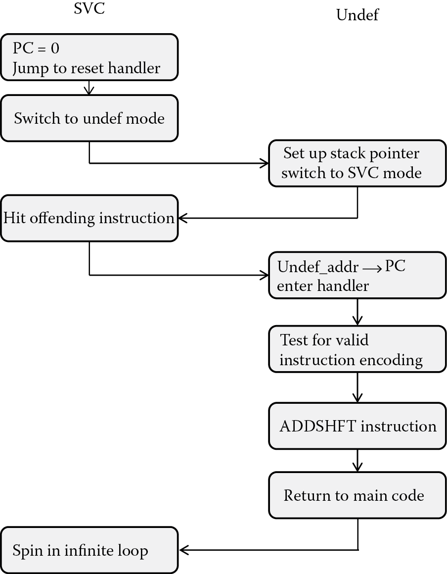
Figure 14.4 shows the basic flow of the program. The first few instructions of the program form the vector table, using PC-relative load instructions at each exception vector. Notice that the reset handler’s address is referenced in the DCD statement
Reset_Addr DCD Reset_Handler
so that when the processor comes out of reset, the first instruction it executes is LDR, which will load the Program Counter with a constant it fetches from memory. Examine the assembler listing and you will notice the PC-relative load instruction and the offset calculated by the linker. The constant in memory is the address of the reset handler, by design. Inside the reset handler, the machine is forced into Undef mode so that we can set up a stack pointer, since we know in advance we are going to switch modes after hitting our strange instruction. The machine is switched back into Supervisor mode afterward. When the processor then tries to execute the bit pattern we deliberately put into the pipeline,
ADDSHFTr0r0r4 DCD 0x77F00FF4 ; r0 = (r0 + r4) LSL #5
it immediately changes the mode to Undef and sets the Program Counter to 0x4, expecting to fetch some type of branch instruction at the exception vector that will ultimately take us to our handler.
Now that the processor has begun exception processing, the instruction at address 0x4 is fetched and executed. This PC-relative load moves the address of our handler into the Program Counter, and fetching begins from there. The first three instructions in the handler save off register and SPSR information to the stack. A comparison is made to determine if the bit pattern the processor rejected was something we wish to support, and if so, the processor branches to the ADDSHFTInstruction routine. When returning from our undefined instruction exception, we restore the SPSR and the register file that was stacked and move the Link Register value into the Program Counter, given as
LDMFD sp!, {r0-r12, PC}^
This particular version of LDM does two things: it loads the Link Register value back into the Program Counter, effectively jumping back to where we left off, and it moves the SPSR back into the CPSR. Astute readers will notice that we made no adjustment to the Program Counter or Link Register values before we jumped back to the main code. We mentioned before that in some cases, such as during a branch and link instruction (BL), the Link Register value may be adjusted due to the fact that the Program Counter points two instructions ahead of the instruction being executed. In this case, the Link Register holds the return address of the instruction following the offending instruction, so the processor will not re-execute the one that caused the exception. For some exceptions, as we’ll see in a moment, you might want to retry an offending instruction. Since we’ve finished handling the exception, the machine automatically changes back to Supervisor mode.
14.8.3 Interrupts
ARM cores have two interrupt lines—one for a fast interrupt (FIQ) and one for a low-priority interrupt (IRQ). If there are only two interrupts in the entire system, then this works well, as there is already some level of prioritization offered. FIQs have a higher priority than IRQs in two ways: they are serviced first when multiple interrupts arise, and servicing an FIQ disables IRQ interrupts. Once the FIQ handler exits, the IRQ can then be serviced. FIQ interrupts also have the last entry in the vector table, providing a fast method of entering the handler, as well as five extra banked registers to use for exception processing.
But with only two lines, how would an SoC with dozens of potential interrupt sources compete for the processor’s time? There are a couple of ways to do this. The first, but not the best way, is to basically wire OR the interrupts coming from peripherals or external devices together. This would then be used to signal an interrupt on one of the two lines going to the processor. However, this would require polling each interrupt source to determine who triggered the interrupt, which would waste thousands of cycles of time (especially if the requesting device is in a hurry and happens to be the last one in the list!) A second way is to use an external interrupt controller, which is a specialized piece of hardware that takes in all of the interrupt lines, assigns priorities to them, and often provides additional information to help the processor, such as a register that can be read for quickly determining who requested the interrupt. When handling interrupts, the processor must first change the Program Counter to either address 0x18 or 0x1C in memory, fetch the instruction that will change the Program Counter, e.g., either a MOV or LDR instruction, then jump to a new address, which is the start of the interrupt handler. The first column of Figure 14.5 shows what happens when you have multiple sources of interrupts. If the incoming lines are wired together or connected to an external interrupt controller, after the processor jumps to the start of the interrupt handler, the handler itself still has to determine which device caused the interrupt, and only after doing so can the processor branch to the correct interrupt handler.
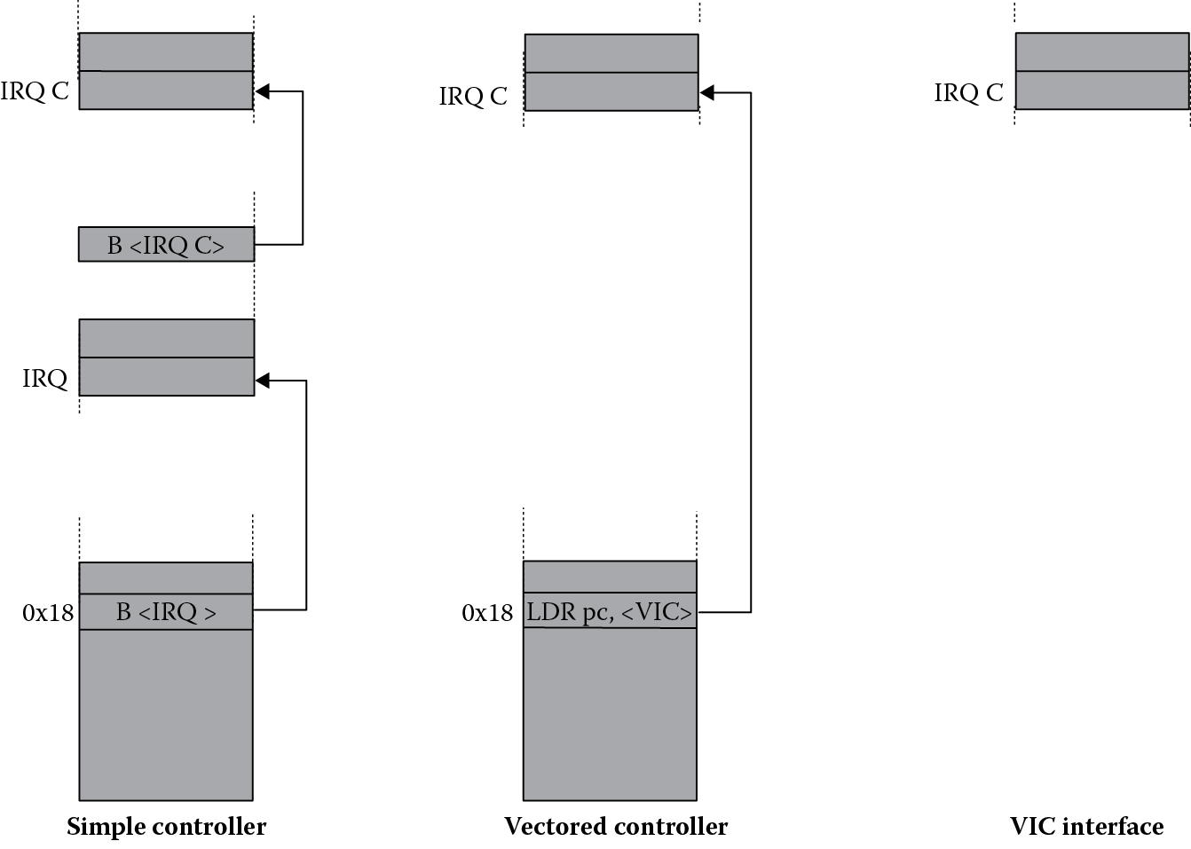
The second column of Figure 14.5 shows the general flow for a better way to handle interrupts. Suppose all of the interrupting peripherals in a system are connected through a controller so that when a device, such as a timer, needs attention (let’s say the timer expired), the controller itself pulls on an interrupt line going to the processor. It also has the ability to give the processor the address of the interrupt handler so that all the processor needs to do is load the address into the Program Counter. The instruction to do so would still sit in the vector table as it did before. Programmers would not be absolved of all duties, however, as a few registers would need to be configured before using such a controller. The modern solution to handle multiple interrupt sources, therefore, is to use what’s known as a vectored interrupt controller (VIC), and given that so many popular microcontrollers have them now, it’s worth a closer look.
14.8.3.1 Vectored Interrupt Controllers
Vectored Interrupt Controllers require a bit of thought and effort but make dealing with interrupts less taxing. For hardware engineers, it makes designs more straightforward, since all the logic needed to build complicated interrupt schemes is already there. Software engineers appreciate the fact that everything is spelled out, but it still requires some work to get registers configured, interrupts enabled and defined, and memory locations initialized. Like the other microcontrollers that we’ve examined so far, the STR910FAM32 contains an ARM core (although this one is an ARM9E-based microcontroller), along with the two AMBA busses (AHB and APB) for interfacing to the memory and peripherals. You can see from Figure 14.6 that the VIC sits off the AHB bus, so it appears as a memory-mapped device. VIC registers exist at memory locations rather than within the processor, a topic we’ll examine in much more detail when we look at memory-mapped peripherals in the Chapter 16. For a complete description of the VIC in the STR910FAM32 microcontroller, consult the STR91xFAxxx Reference Manual (STMicroelectronics 2006).
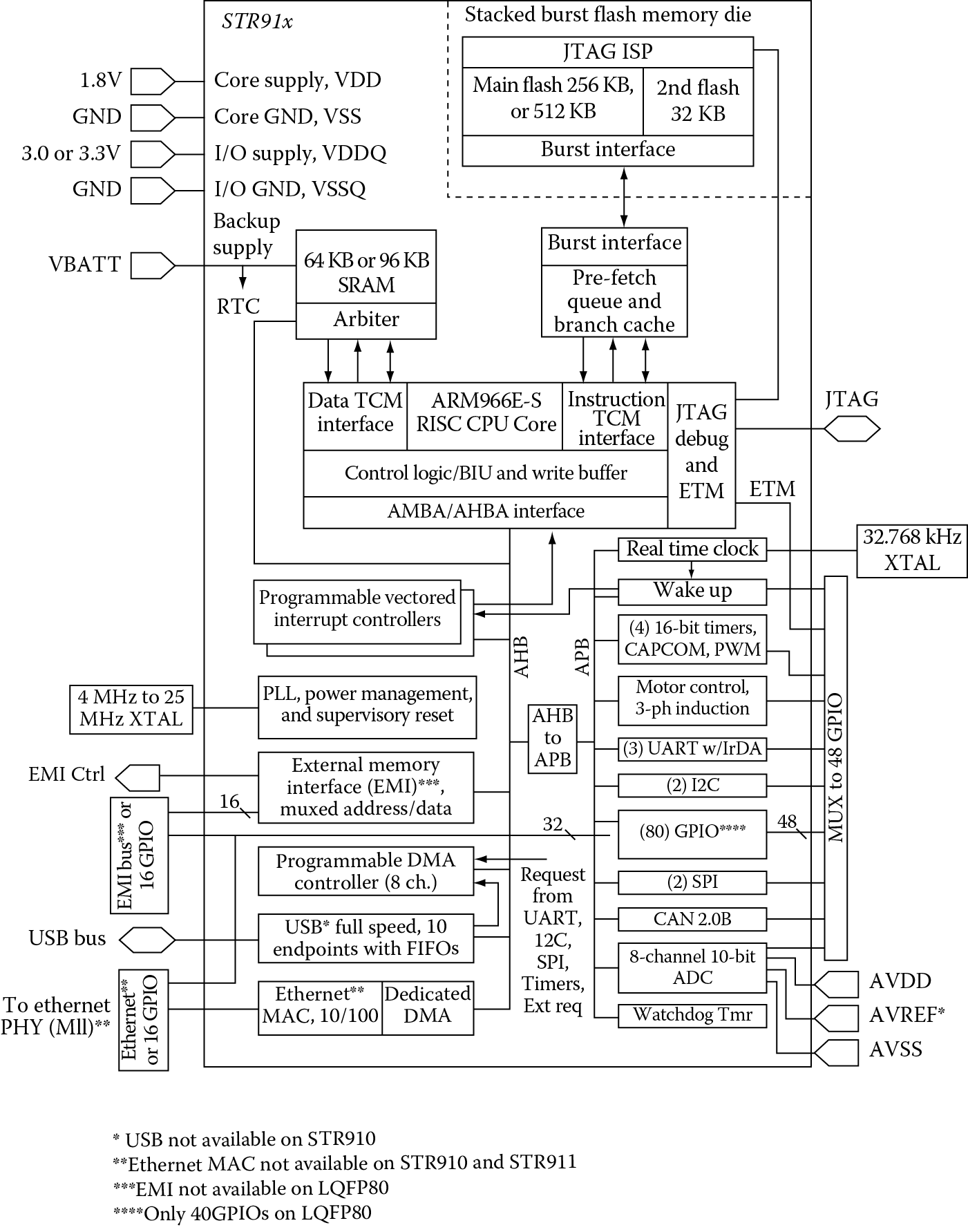
STR910FAM32 microcontroller. (From STMicroelectronics, STR91xF data sheet [Rev4], STMicroelectronics, Geneva, Switzerland. With permission.)
The basic principle behind the VIC is to provide enough information to the processor so that it doesn’t have to go searching through all of the possible interrupts to determine the requester. It has multiple inputs and only two outputs for most cores—the FIQ and IRQ interrupt lines. It also provides the most important component—the address of the interrupt handler. Rather than polling every possible interrupt source, the VIC can simply give the processor the address of the handler in a register. The processor then loads this value into the Program Counter by way of an LDR instruction in the IRQ exception vector.
Example 14.2
To illustrate how a VIC works, on the following pages is some actual code that can be run on the Keil tools. The code itself is a shortened version of the initialization code available for the STR910FAM32 microcontroller.
; Standard definitions of Mode bits and Interrupt (I & F)
; flags in PSRs
SRAM_BASE EQU 0x04000000
VectorAddr EQU 0xFFFFF030 ; VIC Vector Address Register
Mode_USR EQU 0x10
Mode_IRQ EQU 0x12
I_Bit EQU 0x80 ; when I bit is set, IRQ is disabled
F_Bit EQU 0x40 ; when F bit is set, FIQ is disabled
; System Control Unit (SCU) definitions
SCU_BASE EQU 0x5C002000 ; SCU Base Address (non-buffered)
SCU_CLKCNTR_OFS EQU 0x00 ; Clock Control register Offset
SCU_PCGR0_OFS EQU 0x14 ; Peripheral Clock Gating Register 0 Offset
SCU_PCGR1_OFS EQU 0x18 ; Peripheral Clock Gating Register 1 Offset
SCU_PRR0_OFS EQU 0x1C ; Peripheral Reset Register 0 Offset
SCU_PRR1_OFS EQU 0x20 ; Peripheral Reset Register 1 Offset
SCU_SCR0_OFS EQU 0x34 ; System Configuration Register 0 Offset
SCU_CLKCNTR_Val EQU 0x00020000
SCU_PLLCONF_Val EQU 0x000BC019
SCU_PCGR0_Val EQU 0x000000FB
SCU_PCGR1_Val EQU 0x00EC0803
SCU_PRR0_Val EQU 0x00001073
SCU_PRR1_Val EQU 0x00EC0803
PRESERVE8
; Area Definition and Entry Point
; Startup Code must be linked first at Address at which it expects to run.
AREA Reset, CODE, READONLY
ENTRY
ARM
; Exception Vectors Mapped to Address 0.
; Absolute addressing mode must be used.
; Dummy Handlers are implemented as infinite loops which can be modified.
Vectors
LDR pc, Reset_Addr
LDR pc, Undef_Addr
LDR pc, SVC_Addr
LDR pc, PAbt_Addr
LDR pc, DAbt_Addr
NOP ; Reserved Vector
LDR pc, [pc, #-0x0FF0]
LDR pc, FIQ_Addr
Reset_Addr DCD Reset_Handler
Undef_Addr DCD UndefHandler
SVC_Addr DCD SVCHandler
PAbt_Addr DCD PAbtHandler
DAbt_Addr DCD DAbtHandler
DCD 0 ; Reserved Address
IRQ_Addr DCD IRQHandler
FIQ_Addr DCD FIQHandler
UndefHandler B UndefHandler
SVCHandler B SVCHandler
PAbtHandler B PAbtHandler
DAbtHandler B DAbtHandler
IRQHandler B IRQHandler
FIQHandler B FIQHandler
Reset_Handler
; Setup Clock
LDR r0, =SCU_BASE
LDR r1, =0x00020002
STR r1, [r0, #SCU_CLKCNTR_OFS]
; Select OSC as clk src
NOP
; Wait for OSC stabilization
NOP
NOP
NOP
NOP
NOP
NOP
NOP
NOP
NOP
NOP
NOP
LDR r1, =SCU_CLKCNTR_Val
; Setup clock control
STR r1, [r0, #SCU_CLKCNTR_OFS]
LDR r1, =SCU_PCGR0_Val
; Enable clock gating
STR r1, [r0, #SCU_PCGR0_OFS]
LDR r1, =SCU_PCGR1_Val
STR r1, [r0, #SCU_PCGR1_OFS]
; Setup Peripheral Reset
LDR r1, =SCU_PRR0_Val
STR r1, [r0, #SCU_PRR0_OFS]
LDR r1, =SCU_PRR1_Val
STR r1, [r0, #SCU_PRR1_OFS]
; Enter IRQ Mode and set its Stack Pointer
MSR CPSR_c, #Mode_IRQ:OR:I_Bit:OR:F_Bit
LDR sp, =SRAM_BASE + 100
; Enter User Mode
MSR CPSR_c, #Mode_USR
; VIC registers
VIC0_VA7R EQU 0xFFFFF11C ; Vector Address Register for TIM3 IRQ
VIC0_VC7R EQU 0xFFFFF21C ; Vector Control Register for TIM3 IRQ
VIC0_INTER EQU 0xFFFFF010 ; Interrupt Enable Register
; TIM3 registers
TIM3_CR2 EQU 0x58005018 ; TIM3 Control Register 2
TIM3_CR1 EQU 0x58005014 ; TIM3 Control Register 1
LDR r4, =VIC0_VA7R
LDR r5, =IRQ_Handler
STR r5, [r4]
; Setup TIM3 IRQ Handler addr
LDR r4, =VIC0_VC7R
LDR r5, [r4]
ORR r5, r5, #0x27
STR r5, [r4]
; Enable the vector interrupt and specify interrupt number
LDR r4, =VIC0_INTER
LDR r5, [r4]
ORR r5, r5, #0x80
STR r5, [r4] ; Enable TIM3 interrupt
; Timer 3 Configuration (TIM3)
LDR r4, =TIM3_CR2
LDR r5, =0xFF00
LDR r6, =0x200F
LDR r8, [r4]
AND r8, r8, r5 ; Clear prescaler value
ORR r8, r8, r6
; Setup TIM3 prescaler and enable TIM3 timer overflow interrupt
STR r8, [r4]
LDR r4, =TIM3_CR1
LDR r5, =0x8000
LDR r6, [r4]
ORR r6, r6, r5
STR r6, [r4] ; TIM3 counter enable
; main loop
LDR r9, =0xFFFFFFFF
Loop B Loop
IRQ_Handler
SUB lr, lr, #4 ; Update Link Register
SUB r9, r9, #1
STMFD sp!, {r0-r12, lr} ; Save Workspace & LR to Stack
LDR r4, =0x5800501C ; r4 = address of TIM3_SR
LDR r5, =~ 0x2000
LDR r6, [r4]
AND r6, r6, r5
STR r6, [r4] ; Clear Timer Overflow interrupt flag
LDR r0, =VectorAddr ; Write to the VectorAddress
LDR r1, =0x0 ; to clear
STR r1, [r0] ; the respective Interrupt
LDMFD sp!, {r0-r12, PC}^ ; Return to program, restoring state
END
Nearly all of the code sets up registers, initializes clocks, or sets up stack pointers. Note that this example removes some parts that are not critical to demonstrating how interrupts work. You can see all of the EQU directives that assign names to numeric values—this is purely for convenience. Reading code becomes difficult otherwise. The modes are translated into bit patterns, e.g., Mode_USR is equated to 0x10, which is what the lower 5 bits of the CPSR would look like in User mode.
The code actually starts after the first AREA directive, and you can see the exception vector table being built with the label Vectors starting the table. While we normally use LDR instructions to load the PC when a handler is not close enough to use a B (branch) instruction, the method used here is the most general and copes with any memory map. In fact, take a look at the vector table, as shown in Table 14.2. The IRQ vector now contains an instruction that tells the processor to load the PC with a value from memory. The address of that value in memory is calculated using the difference between the Program Counter (which would be 0x20 when this instruction reaches the execute stage of the ARM7TDMI’s pipeline) and the value 0xFF0, giving 0xFFFFF030, which is a strange address and not at all intuitive. It turns out that the VIC has an address register for the processor, called VIC0_VAR, that just happens to sit at address 0xFFFFF030 in memory (STMicroelectronics defined the address—it could have been anything). This register holds the address of our IRQ exception handler, and the address is matched to a particular interrupt source. For example, suppose a timer and a USB interface can both generate interrupts. Inside of the VIC, handler addresses are stored in memory-mapped registers for each interrupt source. So if the USB interface generates an interrupt, its exception handler address is placed in the VIC0_VAR register. If the timer generates an interrupt, then the handler address belonging to the timer is placed in the VIC0_VAR register. Instead of a generic exception handler for interrupts, which would have to spend time figuring out who triggered the IRQ interrupt, the programmer can write a special handler for each type of interrupt and the processor will jump immediately to that unique handler.
Vector Table Showing IRQ Branch Instruction
|
Exception Vector |
Instruction |
|
Reset |
LDR pc, Reset_Addr |
|
Undefined Instruction |
LDR pc, Undef_Addr |
|
SVC |
LDR pc, SVC_Addr |
|
Prefetch Abort |
LDR pc, PAbt_Addr |
|
Data Abort |
LDR pc, DAbt_Addr |
|
Reserved |
NOP |
|
IRQ |
LDR pc, [pc, -0x0FF0] |
|
FIQ |
LDR pc, FIQ_Addr |
In the example code, TIMER3 is used to generate an interrupt when the counter increments from 0x0000 to 0xFFFF. TIMER3 sits on channel 7 by default and its interrupt line goes through VIC0. There are three registers that also need to be set up for VIC0 as shown in Table 14.3. You can see on page 316 where the code equates addresses with the names of the VIC registers. Immediately afterward, the address of the timer’s interrupt handler, called IRQ_Handler, is stored in the VIC0_VA7R register. Remember that if an interrupt is triggered, the VIC will know it was TIMER3 requesting the interrupt, and then it will move the handler’s address from VIC0_VA7R into VIC0_VAR. The remaining code enables and configures the timer.
VIC0 Registers
|
Address |
Register Name |
Function |
|
0xFFFFF010 |
VIC0_INTER |
Interrupt enable register |
|
0xFFFFF11C |
VIC0_VA7R |
Vector address register |
|
0xFFFFF21C |
VIC0_VC7R |
Control register |
The handler itself is at the end of the code. It adjusts the Link Register value first so that we can exit the handler with a single instruction (to be discussed in a moment). The second instruction in the handler begins stacking off registers into memory, including the Link Register. The rest of the handler clears the timer overflow flag in the timer peripheral, and it disables the interrupt request by writing to the VIC0_VAR register. An interrupt handler usually contains the code that clears the source of the interrupt.
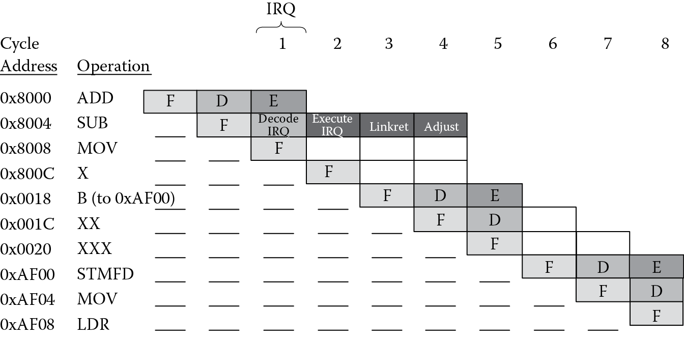
Returning from an interrupt is not difficult, but it does require a little explanation. The timing diagram in Figure 14.7 shows an example sequence of events in the ARM7TDMI processor’s pipeline. Cycle 1 shows the point at which the processor acknowledges that the IRQ line has been asserted. The ADD instruction is currently in the execute stage and must complete, since the processor will allow all instructions to finish before beginning an interrupt exception sequence. In Cycle 2, the processor has now begun handling the IRQ, but notice that the Program Counter has already progressed, i.e., the processor has fetched an instruction from this address, and the PC points to the instruction at 0x800C. It is this value that is loaded into the Link Register in Cycle 3. The exception vector 0x18 becomes the new Program Counter value, and the instruction at this address is fetched, which is a branch instruction. In Cycle 4, the Link Register can be adjusted in the same way that it is for BL instructions, but this makes the address in the Link Register 0x8008, which is four bytes off if we decide to use this address when we’re done with the interrupt handler.
In our example code, the handler adjusts the Link Register value straight away before stacking it. Notice the first instruction in the handler is
SUB lr, lr, #4
This allows us to exit the handler using only a single instruction:
LDMFD sp!, {r0-r12, pc}^
which is a special construct. The LDM instruction restores the contents of the registers from the stack, in addition to loading the PC with the value of the Link Register. The caret (^) at the end of the mnemonic forces the processor to transfer the SPSR into the CPSR at the same time, saving us an instruction. This is the recommended way to exit an interrupt handler.
14.8.3.2 More Advanced VICs
Believe it or not, there is an even faster way of handling interrupts. Referring back to Figure 14.5, we’ve described two methods already, which are shown in the first two columns. The first requires the processor to branch to an address—the start of your interrupt handler. The handler then determines who requested the interrupt, branching to yet another location for the handler. The second method uses a VIC so that the processor still goes to the IRQ exception vector, but instead of branching to a generic handler, it branches to a handler address that is given to it by the VIC.
If the VIC is coupled ever more tightly to the processor, it’s possible to forgo an exception vector completely; ergo, a bus is created on the processor that talks directly to the VIC. As shown in the third column of Figure 14.5, when an interrupt occurs, the processor knows to take the address from the dedicated bus. Recall from the previous example that the VIC has memory-mapped registers that are attached to the AHB bus. When an interrupt occurs, the processor gets its interrupt service routine address from the VIC0_VAR register, which is also on the AHB bus. The third method allows the interrupt service routine’s address to be given to the core on a dedicated address bus, along with handshake lines to signal that the address is stable and that the core has received it. The processor doesn’t even have to go to the exception vector at address 0x18. Since the processor core must be modified to accept a more advanced vectored interrupt controller, this feature is not found on all ARM processors.
14.8.4 Aborts
Aborts have something of a negative connotation to them, but not all of them are bad. Certainly, the processor should be prepared to deal with any that happen to appear, and those that do should be the type that are handled with a bit of extra hardware, since the really awful cases are rare and don’t really provide many graceful exits. The topic of caches, physical and virtual addresses, and memory management units is best left for an advanced text, such as Sloss et al. (2004), Furber (2000), or Patterson and Hennessy (2007), but the general idea is that normally you limit the amount of physical memory in a processor system to keep the cost of the device low. Since the address bus coming out of the processor is 32-bits wide, it can physically address up to 4 GB of memory. A common trick to play on a processor is to allow it to address this much memory while physically only having a much smaller amount, say 128 MB. The hardware that does this is called a memory management unit (MMU). An MMU can swap out “pages” of memory so that the processor thinks it’s talking to memory that isn’t really there. If the processor requests a page that doesn’t exist in memory, the MMU provides an abort signal back to the processor, and the processor takes a data or prefetch abort exception. It’s what happens in the abort handler that determines whether or not the processor actually begins processing an abort exception. Normally, the MMU can try to swap out pages of memory and the processor will try again to load or store a value to a memory location (or fetch an instruction from memory). If it can’t or there is a privilege violation, e.g., a user trying to address memory marked for supervisor use only, then an abort exception may be taken. There are two types of aborts: prefetch aborts on the instruction side and data aborts on the data side.
14.8.4.1 Prefetch Aborts
A prefetch abort can occur if the processor attempts to fetch an instruction from an invalid address. The way the processor reacts depends on the memory management strategy in use. If you are working with a processor with an MMU, for example, an ARM926EJ-S or ARM1136JF-S, then the processor will attempt to load the correct memory page and execute the instruction at the specified address. Without an MMU, this is indicative of a fatal error, since the processor cannot continue without code. If it’s possible, the system should report the error and quit, or possibly just reset the system.
The prefetch abort sequence resembles those of other exceptions. When an abort is acknowledged by the processor, it will fetch the instruction in the exception vector table at address 0xC. The abort handler will then be responsible for either trying to fix the problem or die a graceful death. The offending instruction can be found at address ea < LR-4> if the processor was in ARM state, or ea <LR-2> if the processor was in Thumb state at the time of the exception. You should return from a prefetch abort using the instruction
SUBS PC, LR, #4
which retries the instruction by putting its address into the Program Counter. The suffix “S” on the subtract instruction and the PC as the destination restores the SPSR into the CPSR automatically.
14.8.4.2 Data Aborts
Loads and stores can generate data aborts if the address doesn’t exist or if an area of memory is privileged. Like prefetch aborts, the action taken by the processor depends on the memory management strategy in place. If an MMU is being used, the programmer can find the offending address in the MMU’s Fault Address Register. The MMU can attempt to fix the problem by swapping in the correct page of memory, and the processor can reattempt the access. If there is no MMU in the system, and the processor takes the abort exception, this type of error is fatal, since the processor cannot fix the error and should report it (if possible) before exiting.
There is a subtle difference in the way that certain ARM cores handle data aborts. Consider the instruction
LDR r0,[r1,#8]!
which would cause the base register r1 to be updated after the load completes. Suppose, though, that the memory access results in a data abort. Should the base register be modified? It turns out the effect on the base register is dependent on the particular ARM core in use. Cores such as StrongARM, ARM9, and ARM10 families use what’s known as a “base restored” abort model, meaning the base register is automatically returned to its original value if an abort occurs on the instruction. The ARM7 family of cores uses a “base updated” abort model, meaning the abort handler will need to restore the base register before the instruction can be reattempted. The handler should exit using the instruction
SUBS PC,LR,#8
if the processor wants to retry the load or store instruction again.
14.8.5 SVCs
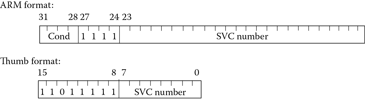
Software interrupts, or SVCs as they are now known, are generated by using the ARM instruction SVC (although you might still see SWI being used in legacy code). This causes an exception to be taken, and forces the processor into Supervisor mode, which is privileged. A user program can request services from an operating system by encoding a request in the 24 bits of the mnemonic for ARM instructions or the 8 bits for Thumb instructions, as shown in Figure 14.8.
Suppose that an embedded system with a keypad and an LCD display are being designed, but only parts of the system are ready—the processor and inputs are ready, but it has no display. The software engineer may choose to use a technique called semihosting to write his or her code, where C primitives such as printf and scanf are simulated by a debugger in the development tools, such as the RealView Developer Suite (RVDS). The printf statements force the output onto a console window in the tools instead of to a nonexistent LCD panel. Semihosting uses SVCs to provide system calls for the user, but these are done in the background without the user noticing. Note that the µVision tools do not support semihosting. Consult the RealView ICE and RealView Trace User Guide from ARM (ARM 2008b) for more information on semihosting and its use.
When an SVC instruction is encountered in the instruction stream, the processor fetches the instruction at the exception vector address 0x8 after changing to Supervisor mode. The core provides no mechanism for passing the SVC number directly to the handler, so the SVC handler must locate the instruction and extract the comment field embedded in the SVC instruction itself. To do this, the SVC handler must determine from which state (ARM or Thumb) the SVC was called by checking the T bit in the SPSR. If the processor was in ARM state, the SVC instruction can be found at ea <LR-4>; for Thumb state, the address is at ea <LR-2>. The SVC number in the instruction can then be used to perform whatever tasks are allowed by the handler.
To return from an SVC handler, use the instruction
MOVS PC, LR
since you wouldn’t want to rerun the instruction after having taken the exception already.
14.9 Exercises
- Name three ways in which FIQ interrupts are handled more quickly than IRQ interrupts.
- Describe the types of operations normally performed by a reset handler.
- Why can you only return from exceptions in ARM state on the ARM7TDMI?
- How many external interrupt lines does the ARM7TDMI have? If you have eight interrupting devices, how would you handle this?
- Write an SVC handler that accepts the number 0x1234. When the handler sees this value, it should reverse the bits in register r9 (see Exercise 2 in Chapter 8). The SVC exception handler should examine the actual SVC instruction in memory to determine its number. Be sure to set up a stack pointer in SVC mode before handling the exception.
- Explain why you can’t have an SVC and an undefined instruction exception occur at the same time.
- Build an Undefined exception handler that tests for and handles a new instruction called FRACM. This instruction takes two Q15 numbers, multiplies them together, shifts the result left one bit to align the binary point, then stores the upper 16 bits to register r7 as a Q15 number. Be sure to test the routine with two values.
- As a sneak peek into Chapter 16, we’ll find out that interrupting devices are programmable. Using STMicroelectronics’ documentation found on its website, give the address range for the following peripherals on the STR910FAM32 microcontroller. They can cause an interrupt to be sent to the ARM processor.
- Real Time Clock
- Wake-up/Interrupt Unit
- Explain the steps the ARM7TDMI processor takes when handling an exception.
- What mode does the processor have to be in to move the contents of the SPSR to the CPSR? What instruction is used to do this?
- When handling interrupts, why must the Link Register be adjusted before returning from the exception?
- How many SPSRs are there on the ARM7TDMI?
- What is a memory management unit (MMU) used for? What is the difference between an MMU and a memory protection unit (MPU)? You may want to consult the ARM documentation or a text like (Patterson, Hennessy 2007) for specific information on both.