Table of Contents for
ARM Assembly Language, 2nd Edition
 ARM Assembly Language, 2nd Edition
Published by
Chapman and Hall/CRC, 2016
ARM Assembly Language, 2nd Edition
Published by
Chapman and Hall/CRC, 2016
- Contents
- ARM Assembly Language: Fundamentals and Techniques, Second Edition
- Preliminaries
- To our families
- Preface
- Acknowledgments
- Authors
- Chapter 1 - An Overview of Computing Systems
- Chapter 2 - The Programmer’s Model
- Chapter 3 - Introduction to Instruction Sets: v4T and v7-M
- Chapter 4 - Assembler Rules and Directives
- Chapter 5 - Loads, Stores, and Addressing
- Chapter 6 - Constants and Literal Pools
- Chapter 7 - Integer Logic and Arithmetic
- Chapter 8 - Branches and Loops
- Chapter 9 - Introduction to Floating-Point: Basics, Data Types, and Data Transfer
- Chapter 10 - Introduction to Floating-Point: Rounding and Exceptions
- Chapter 11 - Floating-Point Data-Processing Instructions
- Chapter 12 - Tables
- Chapter 13 - Subroutines and Stacks
- Chapter 14 - Exception Handling: ARM7TDMI
- Chapter 15 - Exception Handling: v7-M
- Chapter 16 - Memory-Mapped Peripherals
- Chapter 17 - ARM, Thumb and Thumb-2 Instructions
- Chapter 18 - Mixing C and Assembly
- Appendix A: Running Code Composer Studio
- Appendix B: Running Keil Tools
- Appendix C: ASCII Character Codes
- Appendix D
- Glossary
- References
Chapter 11
Floating-Point Data-Processing Instructions
11.1 Introduction
Floating-point operations are not unlike their integer counterparts. The basic arithmetic operations are supported, such as add and subtract, multiply and multiply–accumulate, and divide. Three are unique, however, and they are negate, absolute value, and square root. You will also notice that the logic operations are missing. There are no floating-point Boolean instructions, and no bit manipulation instructions. For these operations, should you need them, integer instructions may be used once the floating-point operand is moved into an ARM register with a VMOV instruction.
Floating-point performance is measured in flops, or floating-point operations per second. Only arithmetic operations are included in the flops calculation, and this measurement has been a fundamental component in comparing floating-point units for decades. Even though the flops measurement is concerned only with arithmetic operations, real floating-point performance is a combination of data transfer capability and data processing. It’s important to do the arithmetic fast, but if the data cannot be loaded and stored as fast as the arithmetic, the performance suffers. We have already considered the varied options for moving data between memory and the FPU, and in Chapter 13 another means, the load and store multiple instructions, will be introduced. In this chapter we look at the arithmetic, and non-arithmetic, instructions available in the Cortex-M4 for floating-point data. This chapter begins with a discussion of the status bits, and then considers the basic instructions in the ARM v7-M floating-point extension instructions.
11.2 Floating-Point Data-Processing Instruction Syntax
Floating-point data-processing instructions have a consistent syntax that makes it easy to use them without having to consult a reference manual. The syntax is shown below.
V<operation>{cond}.F32 {<dest>}, <src1>, <src2>
All floating-point data processing instructions in the Cortex-M4 operate on single-precision data and write a single-precision result, so the only data format is F32 (which can be abbreviated .F). The src1, src2, and dest registers can be any of the single-precision registers, s0 to s31, in the register file. There are no restrictions on the use of registers. Also, the src1, src2, and dest registers can be the same register, different registers, or any two can be the same register. For example, to square a value in register s9 and place the result in register s0, the following multiply instruction could be used:
VMUL.F32 s0, s9, s9
If the value in register s9 is no longer necessary, it could be overwritten by replacing register s0 as the destination register with register s9.
11.3 Instruction Summary
Table 11.1 shows the floating-point data-processing instructions available in the Cortex-M4.
Cortex-M4 Floating-Point Instruction Summary
|
Operation |
Format |
Operation |
|
Absolute value |
VABS{cond}.F32 <Sd>, <Sm> |
Sd = |Sm| |
|
Negate |
VNEG{cond}.F32 <Sd>, <Sm> |
Sd = −1 * Sn |
|
Addition |
VADD{cond}.F32 <Sd>, <Sn>, <Sm> |
Sd = Sn + Sm |
|
Subtract |
VSUB{cond}.F32 <Sd>, <Sn>, <Sm> |
Sd = Sn − Sm |
|
Multiply |
VMUL{cond}.F32 <Sd>, <Sn>, <Sm> |
Sd = Sn * Sm |
|
Negate Multiply |
VNMUL{cond}.F32 <Sd>, <Sn>, <Sm> |
Sd = −1 * (Sn * Sm) |
|
Chained Multiply–accumulate |
VMLA{cond}.F32 <Sd>, <Sn>, <Sm> |
Sd = Sd + (Sn * Sm) |
|
Chained Multiply–Subtract |
VMLS{cond}.F32 <Sd>, <Sn>, <Sm> |
Sd = Sd + (−1 * (Sn * Sm)) |
|
Chained Negate Multiply–accumulate |
VNMLA{cond}.F32 <Sd>, <Sn>, <Sm> |
Sd = (−1 * Sd) + (−1 * (Sn * Sm)) |
|
Chained Negate Multiply–Subtract |
VNMLS{cond}.F32 <Sd>, <Sn>, <Sm> |
Sd = (−1 * Sd) + (Sn * Sm) |
|
Fused Multiply–accumulate |
VFMA{cond}.F32 <Sd>, <Sn>, <Sm> |
Sd = Sd + (Sn * Sm) |
|
Fused Multiply–Subtract |
VFMS{cond}.F32 <Sd>, <Sn>, <Sm> |
Sd = Sd + ((−1 * Sn) * Sm) |
|
Fused Negate Multiply–accumulate |
VFNMA{cond}.F32 <Sd>, <Sn>, <Sm> |
Sd = (−1 * Sd) + (Sn * Sm) |
|
Fused Negate Multiply–Subtract |
VFNMS{cond}.F32 <Sd>, <Sn>, <Sm> |
Sd = (−1 * Sd) + ((−1 * Sn) * Sm) |
|
Comparison |
VCMP{E}{cond}.F32 <Sd>, <Sm> VCMP{E}{cond}.F32 <Sd>, #0.0 |
Sets FPSCR flags based on comparison of Sd and Sm or Sd and 0.0 |
|
Division |
VDIV{cond}.F32 <Sd>, <Sn>, <Sm> |
Sd = Sn/Sm |
|
Square root |
VSQRT{cond} <Sd>, <Sm> |
Sd = Sqrt(Sm) |
11.4 Flags and Their Use
As we saw in Chapter 2, the various Program Status Registers hold the flags and control fields for the integer instructions. Recall from Chapter 9 how the Floating-Point Status and Control Register, the FPSCR, performs the same function for the FPU. One difference between the integer handling of the flags and that of the FPU is in the operations that can set the flags. Only the two compare instructions, VCMP and VCMPE, can set the flags for the FPU. None of the arithmetic operations are capable of setting flags. In other words, there is no S variant for floating-point instructions as with integer instructions. As a result, you will see that the flags are much simpler in the FPU than their integer counterparts, however, the C and V flags are redefined to indicate one or both operands in the comparison is a NaN. The use of the V flag in integer operations to indicate a format overflow is not necessary in floating-point.
11.4.1 Comparison Instructions
The VCMP and VCMPE instructions perform a subtraction of the second operand from the first and record the flag information, but not the result. The two instructions differ in their handling of NaNs. The VCMPE instruction will set the Invalid Operation flag if either of the operands is a NaN, while the VCMP instruction does so only when one or more operands are sNaNs. The check for NaNs is done first, and if neither operand is a NaN, the comparison is made between the two operands. As we mentioned in Chapter 9, infinities are treated in an affine sense, that is,
−infinity < all finite numbers < +infinity
which is what we would expect. If we compare a normal number and a positive infinity, we expect the comparison to show the infinity is greater than the normal number. Likewise, a comparison of a negative infinity with any value, other than a negative infinity or a NaN, will show the negative infinity is less than the other operand.
The VCMP and VCMPE instructions may be used to compare two values or compare one value with zero. The format of the instruction is
VCMP{E}{<cond>}.F32 <Sd>, <Sm>
VCMP{E}{<cond>}.F32 <Sd>, #0.0
The VCMP instruction will set the Invalid Operand status bit (IOC) if either operand is a sNaN. The VCMPE instruction sets the IOC if either operand is a NaN, whether the NaN is signaling or quiet. The flags are set according to Table 11.2.
Floating-Point Status Flags
|
Comparison Result |
N |
Z |
C |
V |
|
Less than |
1 |
0 |
0 |
0 |
|
Equal |
0 |
1 |
1 |
0 |
|
Greater than |
0 |
0 |
1 |
0 |
|
Unordered |
0 |
0 |
1 |
1 |
11.4.2 The N Flag
The N flag is set only when the first operand is numerically smaller than the second operand. Since an overflow is recorded in the OFC status bit, there is no need for the N flag in detecting an overflow condition as in integer arithmetic.
11.4.3 The Z Flag
The Z flag is set only when the first and second operands are not NaN and compare exactly. There is one exception to this rule, and that involves zeros. The positive zero and negative zero will compare equal. That is, when both operands are zero, the signs of the two zeros are ignored.
11.4.4 The C Flag
The C flag is set in two cases. The first is when the first operand is equal to or larger than the second operand, and the second is when either operand is NaN.
11.4.5 The V Flag
The V flag is set only when a comparison is unordered, that is, when a NaN is one or both of the comparison operands.
Example 11.1
The comparisons in Table 11.3 show the operation of the Cortex-M4 compare instructions.
Example Compare Operations and Status Flag Settings
|
Operands |
Flags |
Notes |
||||
|
Sd |
Sm |
N |
Z |
C |
V |
|
|
0x3f800001 |
0x3f800000 |
0 |
0 |
1 |
0 |
Sd > Sm |
|
0x3f800000 |
0x3f800000 |
0 |
1 |
1 |
0 |
Sd = = Sm |
|
0x3f800000 |
0x3f800001 |
1 |
0 |
0 |
0 |
Sd < Sm |
|
0xcfffffff |
0x3f800000 |
1 |
0 |
0 |
0 |
Sd < Sm |
|
0x7fc00000 |
0x3f800000 |
0 |
0 |
1 |
1 |
Sd is qNaN |
|
0x40000000 |
0x7f800001 |
0 |
0 |
1 |
1 |
Sm is sNaN |
11.4.6 Predicated Instructions, or the Use of the Flags
The flags in the FPU may be accessed by a read of the FPSCR and tested in an integer register. The most common use for these flags is to enable predicated operation, as was covered in Chapter 8. Recall that the flag bits used in the determination of whether the predicate is satisfied are the flag bits in the APSR. To use the FPU flags, a VMRS instruction must be executed to move the flags in the FPSCR to the APSR. The format of the VMRS is
VMRS{<cond>} <Rt>, FPSCR
The destination can be any ARM register, r0 to r14, but r13 and r14 are not reasonable choices. To replace the NZCV flag bits in the APSR the <Rt> field would contain “APSR_nzcv.” This operation transfers the FPSCR flags to the APSR, and any predicated instruction will be executed or skipped based on the FPSCR flags until these flags are changed by any of the operations covered in Chapter 7. When using the flags, the predicates are the same as those for integer operations, as seen in Chapter 8 (see Table 8.1).
Example 11.2
Transfer the flag bits in the FPSCR to the APSR.
Solution
The transfer is made with a VMRS instruction, with the destination APSR_nzcv:
VMRS.F32 APSR_nzcv, FPSCR
VMRS is what is known as a serializing instruction. It must wait until all other instructions have completed and the register file is updated to ensure any instruction that could alter the flag bits has completed. Other serializing instructions include the counterpart instruction, VMSR, which overwrites the FPSCR with the contents of an ARM register. This instruction is serializing to ensure changes to the FPSCR do not affect instructions that were issued before the VMSR but have not yet completed.
To modify the FPSCR, for example, to change the rounding mode, the new value must be read from memory or the new rounding mode inserted into the current FPSCR value. To change the current FPSCR value, first move it into an ARM register, modify the ARM register, and then use the VMSR instruction to move the new value back to the FPSCR. The modification is done using the integer Boolean operations. The format for the VMSR instruction is
VMSR{<cond>} FPSCR, <Rt>
Example 11.3
Set the rounding mode to roundTowardZero.
Solution
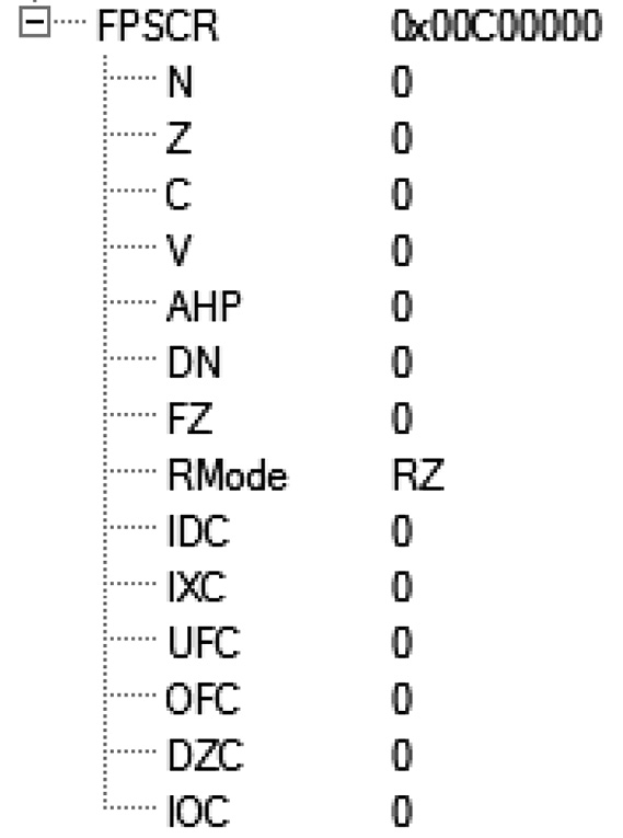
The rounding mode bits are FPSCR[22:23], and the patterns for the rounding mode selection was shown in Chapter 9. To set the rounding mode to roundTowardZero, the bits [22:23] must be set to 0b11. Modifying the FPSCR is done using integer bit manipulation instructions, but the FPSCR must first be copied to an ARM register by the VMRS instruction. The bits can be ORed in using an ORR immediate instruction, and the new FPSCR written to the FPU with the VMSR instruction. The code sequence is below.
VMRS r2, FPSCR ; copy the FPSCR to r2
ORR r2, r2, #0x00c00000 ; force bits [22:23] to 0b11
VMSR FPSCR, r2 ; copy new FPSCR to FPU
After running this code, Figure 11.1 shows the register window in the Keil tools with the change in the FPSCR.
To set the rounding mode back to RN, the following code can be used:
VMRS r2, FPSCR ; copy the FPSCR to r2
BIC r2, r2, #0x00c00000 ; clear bits [22:23]
VMSR FPSCR, r2 ; copy new FPSCR to FPU
Example 11.4
Find the largest value in four FPU registers.
Solution
Assume registers s4, s5, s6, and s7 contain four single-precision values. The VCMP.F32 instruction performs the compares and sets the flags in the FPSCR. These flags are moved to the APSR with the VMRS instruction targeting APSR_nzcv as the destination; the remaining bits in the APSR are unchanged. This allows for predicated operations to be performed based on the latest floating-point comparison.
; Find the largest value in four FPU registers
; s4-s7. Use register s8 as the largest value register
; First, compare register s4 to s5, and copy the largest to s8.
; Then compare s6 to s8, and copy s6 to s8 if it is
; larger. Finally, compare s7 to s8, copying s7 to s8 if
; it is the larger.
; Set up the contents of registers s4-s7 using VLDR
; pseudo-instruction
VLDR.F32 s4, = 45.78e5
VLDR.F32 s5, = -0.034
VLDR.F32 s6, = 1.25e8
VLDR.F32 s7, = -3.5e10
; The comparisons use the VCMP instruction, and the status
; bits copied to the APSR. Predicated operations perform
; the copies
; First, compare s4 and s5, and copy the largest
; to s8. The GT is true if the compare is signed >,
; and the LE is true if the compare is signed < =.
VCMP.F32 s4, s5 ; compare s4 and s5
VMRS APSR_nzcv, FPSCR ; copy only the flags to APSR
VMOVGT.F32 s8, s4 ; copy s4 to s8 if larger than s5
VMOVLE.F32 s8, s5 ; copy s5 if larger or equal to s4
; Next, compare s6 with the new largest. This time only
; move s6 if s6 is greater than s8.
VCMP.F32 s6, s8 ; compare s6 and the new larger
VMRS APSR_nzcv, FPSCR ; copy only the flags to APSR
VMOVGT.F32 s8, s6 ; copy s6 to s8 if new largest
; Finally, compare s7 with the largest. As above, only
; move s7 if it is greater than s8.
VCMP.F32 s7, s8 ; compare s6 and the new larger
VMRS APSR_nzcv, FPSCR ; copy only the flags to APSR
VMOVGT.F32 s8, s7 ; copy s7 to s8 if new largest
; The largest of the 4 registers is now in register s8.
Exit B Exit
11.4.7 A Word about the IT Instruction
The IT instruction was introduced in Chapter 8. Recall that ARM instructions are predicated, with the AL (Always) predicate the default case, used when an instruction is to be executed regardless of the status bits in the APSR. When execution is to be determined by the status bits, as in the example above, a field mnemonic is appended to the instruction, as in VMOVGT seen above. This is true in the ARM instruction set, but not in the Thumb-2 instruction set—this functionality is available through the IT instruction. In the disassembly file, the Keil assembler inserted an IT instruction before the VMOVGT and the VMOVLE instructions as shown below.
0x00000034 BFCC ITE GT
63: VMOVGT.F32 s8, s4 ; copy s4 to s8 if larger than s5
0x00000036 EEB04A42 VMOVGT.F32 s8,s4
64: VMOVLE.F32 s8, s5 ; copy s5 if larger or equal to s4
0x0000003A EEB04A62 VMOVLE.F32 s8,s5
Since the GT and LE conditions are opposites, that is, the pair covers all conditions, only a single IT block is needed.
The Keil tools allow for the programmer to write the assembly code as if the instructions are individually predicated, as in the example above. The assembler determines when an IT block is needed, and how many predicated instructions may be part of the IT block. Each IT block can predicate from one to four instructions. It is a very powerful tool and should be used when the result of a compare operation is used to select only a small number of operations.
11.5 Two Special Modes
Early in the development of ARM FPUs, two modes were introduced which simplified the design of the FPU, enabling a faster and smaller design, but which were not fully IEEE 754-1985 compatible. These two modes are Flush-to-Zero and Default NaN. Both are enabled or disabled by bits in the FPSCR—the Flush-to-Zero mode is enabled by setting the FZ bit, bit [24], and the Default NaN mode is enabled by setting the DN bit, bit [25].
11.5.1 Flush-to-Zero Mode
When the Cortex-M4 is in Flush-to-Zero mode, all subnormal operands are treated as zeros with the sign bit retained, and any result in the subnormal range before rounding is returned as zero with the sign of the computed subnormal result. When an input subnormal operand is treated as a zero, the Input Denormal exception bit (IDC, bit [7] of the FPSCR) is set, but the Inexact status bit is not set. However, when a subnormal result is detected, the Underflow exception (UFC, bit [3] of the FPSCR) is set, but the Inexact status bit is not set.
Note that Flush-to-Zero mode is not compatible with the IEEE 754-2008 specification, which states that subnormal values must be computed faithfully. When would you consider using Flush-to-Zero mode? In early ARM FPUs, a subnormal input or a result in the subnormal range would cause a trap to library code to compute the operation, resulting in potentially thousands of cycles to process the operation faithfully. Unlike these older FPUs, the Cortex-M4 computes all operations with the same number of clock cycles, even when subnormal operands are involved or the result is in the subnormal range. It is unlikely you will ever need to enable the Flush-to-Zero mode.
11.5.2 Default NaN
When in Default NaN mode, the Cortex-M4 treats all NaNs as if they were the default NaN. Recall that the IEEE 754-2008 specification suggests that a NaN operand to an operation should be returned unchanged, that is, the payload, as we discussed in Chapter 9, should be returned as the result. In Default NaN mode this is not the case. Any input NaN results in the default NaN, shown in Table 9.1, regardless of the payload of any of the input NaNs. As with the Flush-to-Zero mode above, it was the case in the earlier FPUs that NaNs would cause a trap to library code to preserve the payload according to the recommended IEEE 754-2008 behavior. However, the Cortex-M4 handles NaNs according to the recommendations of the standard without library code, so it is unlikely you will ever need to enable the Default NaN mode.
11.6 Non-Arithmetic Instructions
Two instructions are referred to as “non-arithmetic” even though they perform arithmetic operations. They are Absolute Value (VABS) and Negate (VNEG). They differ from the other data-processing instructions in that they do not signal an Invalid Operation if the operand is a signaling NaN.
11.6.1 Absolute Value
As you recall, floating-point values are stored in sign-magnitude form, that is, a separate sign bit indicates the sign of the unsigned magnitude. So to make a floating-point value positive simply requires setting the sign bit to zero. This is true for normal and subnormal values, zeros, infinities and NaNs. Contrast this with changing the sign of a two’s complement number and you will see how easy it is in floating-point. The format of the VABS instruction is shown below. While it is a two-operand instruction, it is not uncommon to overwrite the source if only the absolute value of the operand will be used.
VABS{cond}.F32 <Sd>, <Sm>
11.6.2 Negate
The VNEG operation simply flips the sign bit of the source operand and writes the modified result to the destination register. This is true of zero, infinity, and NaN results, as well as all normal and subnormal results. The format of the VNEG instruction is shown below. Like VABS above, it is a two-operand instruction, and it is not uncommon to overwrite the source if only the negative of the operand will be used.
VNEG{cond}.F32 <Sd>, <Sm>
Example 11.5
The result of executing VABS and VNEG on the following values is shown in Table 11.4.
Examples of VABS and VNEG
|
Input Value |
VABS |
VNEG |
Note |
|
0X5FEC43D1 |
0X5FEC43D1 |
0XDFEC43D1 |
Normal value, sign bit modified |
|
0x80000000 |
0x00000000 |
0x00000000 |
Negative zero becomes positive zero for both operations |
|
0x00000000 |
0x00000000 |
0x80000000 |
Positive zero becomes negative after VNEG |
|
0xFF800055 |
0x7F800055 |
0x7F800055 |
Signaling NaN, only the sign bit is changed, and IOC is not set |
|
0x800000FF |
0x000000FF |
0x000000FF |
Subnormal sign changed, and UFC is not set |
11.7 Arithmetic Instructions
Most of the data-processing instructions are arithmetic operations, that is, they will set exception status bits for signaling NaNs. At this point we’ll spend some time looking at the operations in some detail.
11.7.1 Addition/Subtraction
The addition and subtraction instructions have the following format:
VADD{cond}.F32 <Sd>, <Sn>, <Sm>
VSUB{cond}.F32 <Sd>, <Sn>, <Sm>
Recall in Chapter 10 how addition and subtraction can result in unexpected values due to rounding and cancelation, and when operands are infinities and NaNs. For normal and subnormal values, the instructions are straightforward in their use, with any register available as a source or destination register. For example, to double a value in a register, the instruction
VADD.F32 s5, s5, s5
would do so for normal and subnormal values, and avoid having to store a factor of 2.0 in a register.
It is possible with the VADD and VSUB instructions to incur all of the exceptions except divide-by-zero. It is not difficult to see how these operations could overflow and underflow, and it is common to return an inexact result. A signaling NaN can cause an Invalid Operation exception, as can some operations with infinities. Table 11.5 shows how VADD and VSUB behave with the five classes of encodings. In this table, Operand A and Operand B may be either input operand. The notes are directed to the VADD instruction, but also apply to the VSUB when the signs of the operands are different.
Floating-Point Addition and Subtraction Instructions Operand and Exception Table
|
Operand A |
Operand B |
Result |
Possible Exceptions |
Notes |
|
Normal |
Normal |
Normal, Subnormal, Infinity |
OFC, UFC, IXC |
Normal + Normal can overflow, resulting in an infinity or max normal, and if opposite signs, can result in a subnormal value |
|
Normal |
Subnormal |
Normal, Subnormal |
OFC, UFC, IXC |
If opposite signs a subnormal result is possible, otherwise, a normal would result |
|
Normal |
Infinity |
Infinity |
None |
|
|
Normal |
Zero |
Normal |
None |
|
|
Subnormal |
Subnormal |
Normal, Subnormal, Zero |
UFC, IXC |
|
|
Subnormal |
Infinity |
Infinity |
None |
|
|
Subnormal |
Zero |
Subnormal |
None |
|
|
Infinity |
Infinity |
Infinity |
None |
|
|
Infinity |
Zero |
Infinity |
None |
|
|
NaN |
Anything |
NaN |
IOC |
If a signaling NaN, IOC is set |
Example 11.6
Select three pairs of operands that when added using a VADD instruction result in a
- 1. Normal value
- 2. Subnormal value
- 3. Infinity
Solution
- The two operands could be 0x3F800000 (+1.0). The sum would be 0x40000000 (2.0).
- To return a subnormal with two normal input operands, cancelation would have to take place. If the two input operands are 0x00800001 and 0x80800000, the result would be 0x00000001, the minimum subnormal value (1.401 × 10−45).
- To return an infinity, the rounding mode would have to be either RNE or RP, for two positive values, or RNE or RM, for two negative values. As an example, if the rounding mode was RNE, the operands 0x7F7FFFFF and 0x7F700001 would overflow and return an infinity. Likewise, the operands 0xFF7FFFFF and 0xFF700001, would return a negative infinity.
Example 11.7
Select three pairs of operands that when subtracted using a VSUB instruction results in
- 1. Normal value
- 2. Subnormal value
- 3. Infinity
Solution
- The two operands could be 0x3F800000 (+1.0) and 0xBF800000 (−1.0). The sum would be 0x40000000 (2.0).
- To return a subnormal with 2 normal operands, cancelation would have to take place. If the two input operands are 0x00800001 and 0x00800000, the result would be 0x00000001, the minimum subnormal value (1.401 × 10−45).
- To return an infinity, if the rounding mode was RNE, the operands 0xFF7FFFFF and 0x7F700001 would overflow and return a negative infinity. Likewise, the operands 0x7F7FFFFF and 0xFF700001 would return a positive infinity.
11.7.2 Multiplication and Multiply–Accumulate
The Cortex-M4 has a rich variety of multiplication and multiply–accumulate operations, but some can be a bit confusing. Two varieties of multiply–accumulate instructions, chained and fused, are available with options to negate the addend and the product. In early ARM FPUs, only the chained operations were available. For example, the chained VNMLA instruction produces a result equivalent to a sequence of multiply and add operations. If the instruction is
VNMLA.F32 s1, s2, s3
an equivalent sequence of instructions producing the same result would be
VMUL.F32 s2, s2, s3
VNEG.F32 s2, s2
VADD.F32 s1, s1, s2
The advantage is in the single instruction and in compliance to the IEEE 754-1985 standard. Before the introduction of the IEEE 754-2008 standard, no multiply–accumulate could be compliant without rounding the product before the addition of the addend. The chained operations in the Cortex-M4 are a legacy of earlier ARM FPUs that were IEEE 754-1985 standard compliant by performing this rounding step on the product before adding in the addend. With the introduction of the IEEE 754-2008 standard a new set of instructions, referred to as fused multiply–accumulate instructions, were made part of the standard. These instructions compute the product equivalently to the infinitely precise product, and this value, unrounded, is added to the addend. The final sum is rounded to the destination precision. The fused operations are more accurate because they avoid the rounding of the intermediate product, and they are preferred to the chained operations. In some cases of legacy floating-point code, the chained operations may be used to exactly reproduce earlier IEEE 754-1985 standard results, while the fused operations may give different results.
We will first consider the multiply instructions, which include VMUL and VNMUL. Next we will consider the chained multiply–accumulate operations, and finally the fused multiply–accumulate operations.
11.7.2.1 Multiplication and Negate Multiplication
Two multiply instructions are available in the Cortex-M4. VMUL multiplies two operands, writing the result in a destination register. VNMUL first negates the second of the two operands before the multiplication. The formats of the two instructions are shown below.
VMUL{cond}.F32 <Sd>, <Sn>, <Sm>
VNMUL{cond}.F32 <Sd>, <Sn>, <Sm>
Any of the floating-point registers can be a source and destination register. As an example, the following instruction
VMUL.F32 s12, s12, s12
would square a normal value and leave the square in the register. Similarly, if the algorithm called for the negative of the square of a normal value, the instruction
VNMUL.F32 s12, s12, s12
would perform the operation with a single instruction.
The VMUL and VNMUL instructions can generate all of the exceptions apart from the divide-by-zero exception. Overflow and underflow are common, as multiplication can create values both too large and too small to fit in a finite data type. Inexact is also a common consequence of floating-point multiplication. Recall that the Inexact status bit is set whenever an overflow is detected.
Table 11.6 shows how VMUL and VNMUL instructions behave with the five classes of encodings. In this table, Operand A and Operand B may be either input operand.
Floating-Point Multiply Instructions Operand and Exception Table
Operand A
Operand B
Result
Possible Exceptions
Notes
Normal
Normal
Normal, Subnormal, Infinity, Zero
OFC, UFC, and IXC
Normal * Normal can overflow, resulting in an infinity or max normal, or result in a subnormal value or zero
Normal
Subnormal
Normal, Subnormal, Zero
UFC, IXC
The result may be in the normal range, subnormal range, or underflow to a zero
Normal
Zero
Zero
None
As expected in zero arithmetic
Normal
Infinity
Infinity
None
As expected in infinity arithmetic
Subnormal
Subnormal
Zero
UFC, IXC
This case will always result in underflow, with a zero result and UFC and IXC status bits set
Subnormal
Zero
Zero
None
As expected in zero arithmetic
Subnormal
Infinity
Infinity
None
As expected in infinity arithmetic
Zero
Zero
Zero
None
As expected in zero arithmetic
Infinity
Zero
NaN
IOC
Invalid operation
Infinity
Infinity
Infinity
None
As expected in infinity arithmetic
NaN
Anything
NaN
IOC
If a signaling NaN, IOC is set, and SNaN input is quieted
11.7.2.2 Chained Multiply–Accumulate
There are four chained multiply–accumulate operations, providing options to subtract rather than add, and an option to negate the product. The formats of the instructions are shown below.
VMLA{cond}.F32 <Sd>, <Sn>, <Sm>
VMLS{cond}.F32 <Sd>, <Sn>, <Sm>
VNMLA{cond}.F32 <Sd>, <Sn>, <Sm>
VNMLS{cond}.F32 <Sd>, <Sn>, <Sm>
Each of these instructions can be represented by an equivalent set of operations, as shown in Table 11.7. The possible exceptions and default results are the same as those for the component operations discussed above. For example, in a VMLA operation in the RNE rounding mode, if the Sn and Sm operands are two very large normal values, which, when multiplied will overflow to a positive infinity, and the Sd operand is a normal value, the result of the VMLA will be the same as an addition of a normal value and a positive infinity, which is a positive infinity. In understanding the behavior of chained operations, the individual component operations are considered in order separately of the others, and the final result of the chained instructions is the result of the last of the component operations (Table 11.7).
Chained Multiply-Accumulate Operations
Instruction
Operation
Equivalent Operations
VMLA
Chained Multiply–accumulate
Sd = Sd + (Sn * Sm)
Temp = Round(Sn * Sm)
Sd = Round(Sd + Temp)
VMLS
Chained Multiply Subtract
Sd + (−1 * ((Sn * Sm))
Temp = Round(Sn * Sm)
Temp = Negate(Temp)
Sd = Round(Sd + Temp)
VNMLA
Chained Negate Multiply–accumulate
Sd = (−1 * Sd) + (−1 * (Sn * Sm))
Temp = Round(Sn * Sm)
Temp = Negate(Temp)
Temp2 = Negate(Sd)
Sd = Round(Temp2 + Temp)
VNMLS
Chained Negate Multiply Subtract
Sd = (−1 * Sd) + (Sn * Sm)
Temp = Round(Sn * Sm)
Temp2 = Negate(Sd)
Sd = Round(Temp2 + Temp)
Example 11.8
Execute each of VMLA, VMLS, VNMLA, and VNMLS instructions with the following operands:
Sn = −435.792
Sm = 10.0
Sd = 5832.553
Solution
Using a tool such as the conversion tools at (http://babbage.cs.qc.cuny.edu/IEEE-754.old/Decimal.html), the single-precision values for Sn, Sm, and Sd are:
Sn: 0xC3D9E560
Sm: 0x41200000
Sd: 0x45B6446D
The following code implements the solution.
ADR r1, MulAddTestData
VLDR.F32 s0, [r1] ; Sn
VLDR.F32 s1, [r1, #4] ; Sm
VLDR.F32 s2, [r1, #8] ; Sd
; VMLA
VMLA.F32 s2, s0, s1
; VMLS
VLDR.F32 s2, [r1, #8] ; Reload Sd
VMLS.F32 s2, s0, s1
; VNMLA
VLDR.F32 s2, [r1, #8] ; Reload Sd
VNMLA.F32 s2, s0, s1
; VNMLS
VLDR.F32 s2, [r1, #8] ; Reload Sd
VNMLS.F32 s2, s0, s1
B Exit
ALIGN
MulAddTestData
DCD 0xC3D9E560 ; −435.792DCD 0x41200000 ; 10.0
DCD 0x45B6446D ; 5832.553
When this code is run, the destination register s2 contains the following for each of the four operations:
VMLA: s2 = 0x44B85444, which is 1474.633.
VMLS: s2 = 0x461F39E4, which is 10,190.473
VNMLA: s2 = 0xC4B85444, which is −1474.633VNMLS: s2 = 0xC61F39E4, which is −10,190.473Confirm for yourself that the answers are correct for each of the four operations.
11.7.2.3 Fused Multiply–Accumulate
The Cortex-M4 implements a second set of multiply–accumulate operations that are referred to as fused. Unlike the chained operations discussed above, the fused operations do not round the product, but maintain the product in an infinitely precise, unrounded form. The addend is then added to the product. By eliminating the rounding of the product, the result may have greater accuracy. In most cases this will never be an issue, but in algorithms such as those used to compute transcendental functions, the accuracy of the fused operations enables writing library functions with lower error bounds compared to discrete or chained instructions.
The fused multiply–accumulate instructions have the formats shown below.
VFMA{cond}.F32 <Sd>, <Sn>, <Sm>
VFMS{cond}.F32 <Sd>, <Sn>, <Sm>
VFNMA{cond}.F32 <Sd>, <Sn>, <Sm>
VFNMS{cond}.F32 <Sd>, <Sn>, <Sm>
It is useful to consider these instructions, as we did the chained instructions above, as implementing a series of operations. The first thing to notice is the function of the two negate instructions differs from the chained operations. The chained instruction VNMLA instruction is analogous to the fused VFNMS instruction, while the chained VNMLS instruction is analogous to the fused VFNMA instruction. Table 11.8 shows the instructions, the operations, and the equivalent operations.
Fused Multiply–Accumulate Instructions Equivalent Operations
Instruction
Operation
Equivalent Operations
VFMA
Fused Multiply–accumulate
Sd = Sd + (Sn * Sm)
Temp = (Sn * Sm)
Sd = Round(Sd + Temp)
VFMS
Fused Multiply Subtract
Sd = Sd + ((−1 * Sn) * Sm)
Temp = Negate(Sn)
Temp = (Temp * Sm)
Sd = Round(Sd + Temp)
VFNMA
Fused Negate Multiply–accumulate
Sd = (−1 * Sd) + (Sn * Sm)
Temp = (Sn * Sm)
Temp2 = Negate(Sd)
Sd = Round(Temp2 + Temp)
VFNMS
Fused Negate Multiply Subtract
Sd = (−1 * Sd) + ((−1 * Sn) * Sm)
Temp = Negate(Sn)
Temp = (Temp * Sm)
Temp2 = Negate(Sd)
Sd = Round(Temp2 + Temp)
Example 11.9
Evaluate the accuracy of three random operands in the range (0,1.0) using both the VMLA and the VFMA instructions.
Solution
Consider these three operands (each is computed to full precision):
Sn: 0x3F34FE23 (0.707002818584442138671875)
Sm: 0x3E78EE2A (0.2430960237979888916015625)
Sd: 0x3F7F3DCA (0.99703657627105712890625)
The computed result of Sd + (Sn * Sm) (to 24 digits, the precision of our input operands) is 1.16890615028290589805237. The results are shown in Table 11.9.
Results of Example 11.9
Instruction
Cortex-M4 Result (Hex)
Cortex-M4 Result (Decimal)
Difference from the Computed Result (%)
VMLA
0x3F959EB8
1.16890621185302734375
0.00000527
VFMA
0x3F959EB7
1.16890609264373779296875
0.00000493
As you can see, the difference is one ulp in the final result, or 2−23. Not very much. In fact, the VMLA results differ from the full precision result by just over 5 × 10⁻⁶%, while the fused is only very slightly more accurate! Overall, the computations show very little difference between the two instructions; the computation for both instructions shows very high accuracy, and the use of fused over chained, in this example, has very little impact.
But this doesn’t tell the whole story. Some pathological cases exist which can return very different results. Take the following inputs as an example:
s0 = 0x3F800001 (1.0 + 2−23, or 1.0 + 1 ulp)
s1 = 0x3F800001
s2 = 0xBF800002 (−(1.0 + 2−22), or −(1.0 + 2 ulps))
When input to the chained VMLA instruction the result will be zero. The square of 0x3F800001 will result in a fraction with 1’s in the 20, 2−22, and 2−46 bit positions internal to the hardware. When rounded in RNE, the 2−46 contribution is dropped, leaving only 20 + 2−22, the same fraction as the 0xBF800002 operand. The VFMA does not round, so the 2−46 contribution is retained, and the result is 0x2880000, or 2−46. This case shows a greater error when the inputs are changed just a bit. Consider these operands input to both operations:
s0 = 0x3FC00001 (1.5 + 2−23, or 1.5 + 1 ulp)
s1 = 0x3FC00001
s2 = 0xC0100002 (−(2.25 + 2−22), or –(2.25 + 2 ulps))
The result of the VMLA will again be zero, but the VFMA returns 2−23 as the result. The answer to why this is so is left as an exercise.
One more situation is worth noting. When using the fused multiply–accumulate instructions, you don’t have to worry about exceptions generated by the multiply operation, because these will be reflected in the final result if they impact the final result. For example, consider the following inputs to the VMLA instruction:
s0 = 0x7F000001 (just greater than ½ max normal)
s1 = 0x40000000 (2.0)
s2 = 0xFF7FFFFF (negative, and just under max normal)
If we execute the VMLA instruction:
VMLA.F32 s2, s0, s1
the result is a positive infinity, and the OFC and IXC status bits are set. Why? The product of 0x7F000001 and 0x40000000 overflowed, and an infinity was substituted for the product, and input to the final addition. The infinity plus the very large negative value resulted in an infinity.
If the same inputs are made to the VFMA instruction:
VFMA.F32 s2, s0, s1
the result is 0x74400000, and no exception status bits are set. Since the intermediate product is not evaluated for overflow but rather input with the extended range of the intermediate, infinitely precise value, it is not replaced with an infinity. The addition of the negative addend brings the sum back into the normal range.
11.7.3 Division and Square Root
Both division and square root instructions are available in the Cortex-M4. VDIV divides the first source operand by the second source operand, writing the result in a destination register. VSQRT performs the square root operation. The formats of the two instructions are shown below.
VDIV{cond}.F32 <Sd>, <Sn>, <Sm>
VSQRT{cond}.F32 <Sd>, <Sm>
Any of the floating-point registers can be a source and destination register. As an example, the following instruction
VDIV.F32 s21, s8, s1
would divide the value in register s8 by the value in register s1, and put the rounded quotient in register s21.
Division will result in a divide-by-zero exception, setting the DZC status bit if the divisor is a zero and the dividend is normal or subnormal. Overflow and underflow are possible when the result of the division would result in a value too large or too small, respectively, for representation in the single-precision format. Any division with normal or subnormal values can produce an inexact result and set the IXC status bit.
Table 11.10 shows how the VDIV instruction functions with the five classes of encodings. In this table, Operand A is the dividend and Operand B the divisor. If the result is not exact, the Inexact status bit, IXC, will be set. Recall that the Underflow status bit, UFC, is set when a subnormal result is generated and the result is either not exact or a zero due to a result smaller in magnitude than can be represented in the destination precision. If the computed result is too small, the UFC and IXC status bits will be set and a signed zero result returned.
Floating-Point Divide Instruction Operand and Exception Table
Operand A
Operand B
Result
Possible Exceptions
Notes
Normal
Normal
Normal, Subnormal, Infinity, Zero
OFC, UFC, and IXC
Normal/Normal can overflow, resulting in an infinity or max normal, or result in a subnormal value or zero
Normal
Subnormal
Normal, Infinity
OFC, IXC
The result may be in the normal range, subnormal range, or underflow to a zero.
Normal
Zero
Infinity
DZC
Divide by zero
Normal
Infinity
Zero
None
As expected for an infinity divisor
Subnormal
Normal
Normal, Subnormal, Zero
UFC, IXC
Subnormal/Normal may be normal or subnormal, or zero. UFC and IXC are set if subnormal and inexact, or if zero.
Subnormal
Subnormal
Normal
IXC
If exact, IXC is not set
Subnormal
Infinity
Zero
None
As expected for an infinity divisor
Subnormal
Zero
Infinity
DZC
Divide by zero
Zero
Normal
Zero
None
As expected for a zero dividend
Zero
Subnormal
Zero
None
Zero
Infinity
Zero
None
Zero
Zero
NaN
IOC
Invalid operation
Infinity
Normal
Infinity
None
As expected for an infinity dividend
Infinity
Subnormal
Infinity
None
Infinity
Infinity
NaN
IOC
Invalid operation
Infinity
Zero
Infinity
None
Odd, perhaps, but the infinity governs the result, which is infinity.
Anything
NaN
NaN
IOC
If a signaling NaN, IOC is set and NaN is quieted.
Only the Invalid Operation and Inexact exceptions are possible with square root. Any positive normal or subnormal operand may produce an inexact result and set the IXC status bit. When an operand is a negative normal or subnormal value, and not a negative NaN, the operation is invalid, the default NaN is returned and the IOC status bit is set.
Table 11.11 shows how VSQRT instruction functions with the five classes of encodings and signed values.
Floating-Point Square Root Instruction Operand and Exception Table
Operand A
Result
Possible Exceptions
Notes
+Normal
+Normal
IXC
−Normal
Default NaN
IOC
Any input below zero results in an invalid operation
+Subnormal
+Normal
IXC
−Subnormal
Default NaN
IOC
Any input below zero results in an invalid operation
+Infinity
+Infinity
None
−Infinity
Default NaN
IOC
+Zero
+Zero
None
−Zero
−Zero
None
NaN
NaN
IOC
If a signaling NaN, IOC is set. NaN should be input NaN
11.8 Putting It All Together: A Coding Example
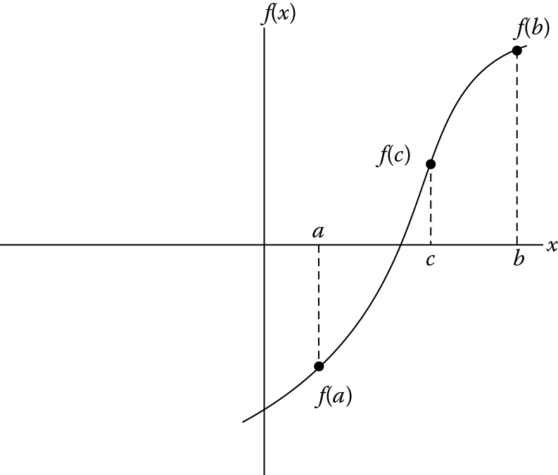
In this section, we’ll tie everything together by coding a routine for the bisection algorithm, which is a simple method of finding a root (a zero crossing) of a continuous function. The algorithm begins with two points on the function that have opposite signs and computes a third point halfway between the two points. The new third point replaces one of the original points that has the same sign as the function evaluated at that new third point, and the algorithm repeats. In Figure 11.2, the original points are labeled a and b, and we see that f(a) and f(b) have opposite signs. The computed third point, c, is the result of one iteration. Further iteration will result in a computed new point closer to the true crossing. The algorithm is ended when the computed point is exactly on the zero crossing (f(c) = 0) or the difference between the input point with the same sign as the computed point is below a threshold.
The algorithm is written in pseudo-code as shown below.*
INPUT: Function f, endpoint values a, b, tolerance TOL, maximum iterations NMAX
CONDITIONS: a < b, either f(a) < 0 and f(b) > 0 or f(a) > 0 and f(b) < 0
OUTPUT: value which differs from a root of f(x) = 0 by less than TOL
N ← 1While N ≤ NMAX {limit iterations to prevent infinite loop
c ← (a + b)/2 new midpoint
If (f(c) = 0 or (b – a)/2 < TOL then {solution found
Output(c)Stop
}
N ← N + 1 increment step counter
If sign(f(c)) = sign(f(a)) then a ← c else b ← c new interval
}
Output(“Method failed.”) max number of steps exceeded; Bisection code
; The algorithm requires the first two points,
; a, and b, to be one below and one above the
; root; that is, f(a) will have an opposite
; sign to f(b). The algorithm computes the midway
; point between a and b, called c, and computes f(c).
; This new point replaces the point with the same
; function result sign. If f(a) is positive and f(c)
; is positive, c replaces a, and the algorithm reruns
; with b and c as points. The algorithm exits when f(c)
; is zero, or (a-b) is less than a threshold value.
; FPU registers
; s6 - the threshold value, 0.0002
; s7 - 2.0, to divide the sum for the new operand
; s8 - operand a
; s9 - operand b
; s10 - the new point, operand c
; s11 - f(a)
; s12 - f(b)
; s13 - f(c)
; ARM registers
; r1 - sign of f(a)
; r2 - sign of f(b)
; r3 - sign of f(c)
; r4 - iteration count
; Choose 0 and 4 as initial samples
; Initialize the divisor register and threshold
VMOV.F32 s7, #2.0
VLDR.F32 s6, = 0.0002
; Initialize the operand registers
VSUB.F32 s8, s7, s7 ; a lazy way to create 0.0
VMOV.F32 s9, #4.0
; Initialize our loop counter
MOV r4, #0
Loop
; Increment our loop counter
ADD r4, r4, #1
; Test a and b for (a-b) < threshold
; Use s11 for the difference, we will overwrite
; it in the eval of operand a
VSUB.F32 s11, s8, s9 ; compute the difference
VABS.F32 s11, s11 ; make sure diff is positive
VCMP.F32 s11, s6 ; test diff > threshold?
VMRS.F32 APSR_nzcv, FPSCR ; copy status bits to APSR
BLS Exit ; if neg or eq, exit
; Evaluate the function for operand a
VMOV.F32 s1, s8
BL func
VMOV.F32 s11, s0
; Evaluate the function for operand b
VMOV.F32 s1, s9
BL func
VMOV.F32 s12, s0
; Compute the midpoint for operand c,
; the point halfway between operands
; a and b
VADD.F32 s10, s8, s9
VDIV.F32 s10, s10, s7
; Evaluate the function for operand c
VMOV.F32 s1, s10
BL func
VMOV.F32 s13, s0
; Test the signs of the three operands
VCMP.F32 s11, #0 ; set status bits only on operand a
VMRS.F32 r1, FPSCR
AND r1, r1, #0x80000000 ; isolate the N status bit
VCMP.F32 s12, #0 ; set status bits only on operand b
VMRS.F32 r2, FPSCR
AND r2, r2, #0x80000000 ; isolate the N status bit
VCMP.F32 s13, #0 ; set status bits only on operand c
VMRS.F32 r3, FPSCR
TST r3, #0x4000000 ; test for zero
BEQ Exit ; the value in s10 is exactly
; the root
AND r3, r3, #0x80000000 ; isolate the N status bit
; If sign(a) ! = sign(c), copy s10 into s9;
; else sign(b) ! = sign(c), copy s10 into s8;
EORS r1, r3 ; test if sign(a) = sign(c)
VMOVEQ.F32 s8, s10 ; if 0, copy c to a
BLEQ Loop ; run it again with a new a
VMOV.F32 s9, s10 ; if not a, then copy c into b
BL Loop ; run it again with a new b
Exit
B Exit
; Test functions
; Assumes ATPCS - regs s0-s15 parameters and/or scratch
; Register usage:
; s0 - return result
; s1 - input operand
; s2 - scratch
; s3 - scratch
func
; Function - x^3 + 2x - 8
VMOV.F32 s0, #2.0 ; use s0 to hold 2.0 temporarily
VMUL.F32 s2, s1, s1 ; initial squaring of input
VMUL.F32 s3, s1, s0 ; multiply input by 2
VMOV.F32 s0, #8.0 ; use s0 to hold 8.0 temporarily
VMUL.F32 s2, s2, s1 ; finish cubing of input
VSUB.F32 s3, s3, s0 ; subtract off 8.0 from 2x
VADD.F32 s0, s2, s3 ; add in x^3 to return reg
BX lr ; return
11.9 Exercises
- 1. Complete the table for a VCMP instruction and the following operands.
Operand A
Operand B
N
Z
C
V
0xFF800000
0x3F800000
0x00000000
0x80000000
0x7FC00005
0x00000000
0x7F80000F
0x7F80000F
0x40000000
0xBF000000
- Give the instructions to implement the following algorithm. Assume y is in register s0, and return x in register s0.
x = 8y2 − 7y + 12
- Expand the code above to create a subroutine that will resolve an order 2 polynomial with the constant for the square term in register s0, the order 1 term in register s1, and the constant factor in register s2. Return the result in register s0.
- Give the instructions to perform the following loop over an one-dimensional array X of 20 data values in memory at address 0x40000100 and an one-dimensional array Y of data values in memory at address 0x40000200. Use a constant value of A between 2.0 and 10.0. The new y value should overwrite the original value.
y = Ax + y
- Modify the program in Example 11.4 to order the four values in registers s8 to s11 in order from smallest to largest.
- In the third case in Example 11.9 (Section 11.7.2.3) the error of the VMLA was 2−23. Show why this is the case.
- Write a division routine that checks for a divisor of zero, and if it is, returns a correctly signed infinity without setting the DZC bit. If the divisor is not zero, the division is performed.
- Add to the program of Exercise 7 a check on a divisor that is 2.0. If it is, perform a multiplication of 0.5 rather than do the division.
- Write a subroutine that would perform a reciprocal operation on an input in register s0, returning the result in register s0.
** The code is taken from the Wikipedia entry on “Bisection method,” taken from http://en.wikipedia.org/wiki/Bisection_method#CITEREFBurdenFaires1985.