Table of Contents for
ARM Assembly Language, 2nd Edition
 ARM Assembly Language, 2nd Edition
Published by
Chapman and Hall/CRC, 2016
ARM Assembly Language, 2nd Edition
Published by
Chapman and Hall/CRC, 2016
- Contents
- ARM Assembly Language: Fundamentals and Techniques, Second Edition
- Preliminaries
- To our families
- Preface
- Acknowledgments
- Authors
- Chapter 1 - An Overview of Computing Systems
- Chapter 2 - The Programmer’s Model
- Chapter 3 - Introduction to Instruction Sets: v4T and v7-M
- Chapter 4 - Assembler Rules and Directives
- Chapter 5 - Loads, Stores, and Addressing
- Chapter 6 - Constants and Literal Pools
- Chapter 7 - Integer Logic and Arithmetic
- Chapter 8 - Branches and Loops
- Chapter 9 - Introduction to Floating-Point: Basics, Data Types, and Data Transfer
- Chapter 10 - Introduction to Floating-Point: Rounding and Exceptions
- Chapter 11 - Floating-Point Data-Processing Instructions
- Chapter 12 - Tables
- Chapter 13 - Subroutines and Stacks
- Chapter 14 - Exception Handling: ARM7TDMI
- Chapter 15 - Exception Handling: v7-M
- Chapter 16 - Memory-Mapped Peripherals
- Chapter 17 - ARM, Thumb and Thumb-2 Instructions
- Chapter 18 - Mixing C and Assembly
- Appendix A: Running Code Composer Studio
- Appendix B: Running Keil Tools
- Appendix C: ASCII Character Codes
- Appendix D
- Glossary
- References
Chapter 15
Exception Handling
v7-M
15.1 Introduction
With the introduction of the Cortex-M3 in 2006, ARM decided to move its considerable weight into the huge market for microcontrollers, devices that normally get very little attention as they’re embedded into everything from printers to industrial meters to dishwashers. Building on the success of the ARM7TDMI, which incidentally was and continues to be used in microcontrollers (particularly Bluetooth devices), the version 7-M cores like the Cortex-M4 support deeply embedded applications requiring fast interrupt response times, low gate counts, and peripherals like timers and pulse width modulation (PWM) signal generators. In some ways, these processors are easier to work with and in some ways, more difficult. Theoretically, one should not be programming a Cortex-M3 or a Cortex-M4 device by writing assembly (but we will!). They are designed to be completely accessible using only C, with libraries available to configure vector tables, the MPU, interrupt priorities, etc., which makes the programmer’s job easier. Very little assembly code ever has to be written. If, however, you are writing assembly, there are only two modes instead of seven and fewer registers to worry about. What makes these processors slightly more difficult to work with is the sheer number of options available: there are more instructions; priority levels can be set on the different interrupt types; there are subpriorities available; faults must be enabled before they can be handled; the Nested Vectored Interrupt Controller must be configured before using it (and while implementation specific, Cortex-M parts can support up to 496 external interrupt inputs!); and there are power management features to consider. In Chapter 14, we saw the exception model for the ARM7TDMI, which is different than the one for version 7-M processors. Here, we’ll examine the basics of handling exceptions for a processor like the Cortex-M4 without covering every single variable, since you are not likely to encounter every exception while you learn about programming, and there are quite a few options to consider when you have multiple exceptions arriving at the same time, some with higher priorities than others. For more advanced topics such as embedded operating systems, semaphores, tail-chaining interrupts, and performance considerations, books such as (Yiu 2014) and the Cortex-M4 Technical Reference Manual (ARM 2009) can be read for details.
15.2 Operation Modes and Privilege Levels
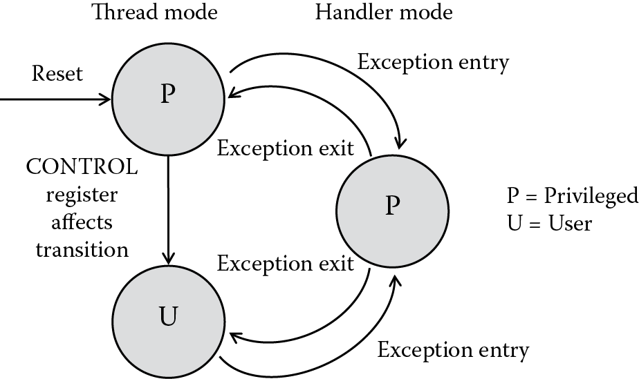
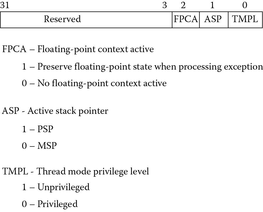
The Cortex-M3 and Cortex-M4 processors have only two operation modes: Handler mode and Thread mode. This is a significant departure from the earlier ARM models where the mode was determined more or less by what the processor was doing, e.g., handling an interrupt or taking an exception. Rather than having unique modes for the different exception types, the Cortex-M processors use Handler mode for dealing with exceptions and everything else runs in Thread mode. One further distinction is introduced, and this has to do with privilege levels. Obviously, you would not want a user application to be able to modify critical parts of a system like configuration registers or the MPU, and it is important that an operating system has the ability to access all memory ranges and registers. There are, then, two privilege levels, aptly named privileged and user. You can see from Figure 15.1 that when the processor comes out of reset, it immediately runs in privileged Thread mode. Once the system is configured, the processor can be put into non-privileged Thread mode by changing the least significant bit of the CONTROL register, shown in Figure 15.2. When the processor takes an exception, it switches to Handler mode, which is always privileged, allowing the system to deal with any issues that may require restricted access to resources. Upon returning from the exception, the processor will revert back to the state from which it left, so there is no way for a user program to change the privilege level by simply changing a bit. It must use an exception handler (which forces the processor into a privileged level) that controls the value in the CONTROL register.
Example 15.1
We’ll return to this example later in the chapter, with some modifications along the way, as it demonstrates the various aspects of exception handling in the Cortex-M4. Let’s begin by building a quick-and-dirty routine that forces the processor into privileged Handler mode from privileged Thread mode. In Chapter 7, the idea of trapping division by zero was only mentioned, leaving an actual case study until now. If you type the following example into the Keil tools, using a Tiva TM4C1233H6PM as the target processor, and then single-step through the code, just out of reset the processor will begin executing the instructions after the label Reset_Handler. Note that many of the registers are memory mapped. For the full list of registers, see the Tiva TM4C1233H6PM Microcontroller Data Sheet (Texas Instruments 2013b).
Stack EQU 0x00000100
DivbyZ EQU 0xD14
SYSHNDCTRL EQU 0xD24
Usagefault EQU 0xD2A
NVICBase EQU 0xE000E000
AREA STACK, NOINIT, READWRITE, ALIGN = 3
StackMem
SPACE Stack
PRESERVE8
AREA RESET, CODE, READONLY
THUMB
; The vector table sits here
; We’ll define just a few of them and leave the rest at 0 for now
DCD StackMem + Stack ; Top of Stack
DCD Reset_Handler ; Reset Handler
DCD NmiISR ; NMI Handler
DCD FaultISR ; Hard Fault Handler
DCD IntDefaultHandler ; MPU Fault Handler
DCD IntDefaultHandler ; Bus Fault Handler
DCD IntDefaultHandler ; Usage Fault Handler
EXPORT Reset_Handler
ENTRY
Reset_Handler
; enable the divide-by-zero trap
; located in the NVIC
; base: 0xE000E000
; offset: 0xD14
; bit: 4
LDR r6, =NVICBase
LDR r7, =DivbyZ
LDR r1, [r6, r7]
ORR r1, #0x10 ; enable bit 4
STR r1, [r6, r7]
; now turn on the usage fault exception
LDR r7, =SYSHNDCTRL (p. 163)
LDR r1, [r6, r7]
ORR r1, #0x40000
STR r1, [r6, r7]
; try out a divide by 2 then a divide by 0!
MOV r0, #0
MOV r1, #0x11111111
MOV r2, #0x22222222
MOV r3, #0x33333333
; this divide works just fine
UDIV r4, r2, r1
; this divide takes an exception
UDIV r5, r3, r0
Exit B Exit
NmiISR B NmiISR
FaultISR B FaultISR
IntDefaultHandler
; let’s read the Usage Fault Status Register
LDR r7, =Usagefault
LDRH r1, [r6, r7]
TEQ r1, #0x200
IT NE
LDRNE r9, =0xDEADDEAD
; r1 should have bit 9 set indicating
; a divide-by-zero has taken place
done B done
ALIGN
END
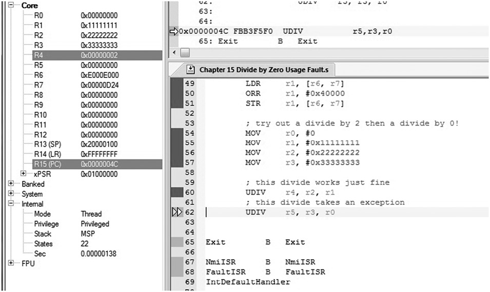
Continue single-stepping through the MOV and LDR instructions until you come to the first of the two UDIV (unsigned divide) operations. If you examine the registers and the state information using the Keil tools, you see that the first divide instruction is perfectly legal, and it will produce a value in register r2. More importantly, the machine is operating in Thread mode and it is privileged, shown in Figure 15.3. If you try to execute the next divide instruction, one which tries to divide a number by zero, you should see the machine change modes to Handler mode. The program has enabled a particular type of exception (usage faults, which we’ll cover in Section 15.6) and enabled divide-by-zero traps so that we can watch the processor begin working on the exception. At this point, the exception routine does not return back to the main code, but in the next example, we’ll add an instruction to effect the return.
Example 15.2
To switch privilege levels, the CONTROL register must be used, and this can only be written in a privileged level, so either the processor must be in Handler mode or privileged Thread mode. If we change the exception handler instructions, we can switch the privilege level of the processor. Additionally, we’ll add a branch instruction (BX) that will allow the processor to exit exception handling and restore the values placed on the stack. You will notice that the original divide-by-zero exception remains, so that when we return to the main code, the processor will attempt to re-execute the offending instruction. For now, stop your simulation at that point. Our clumsy handler code should then read as:
IntDefaultHandler
; let’s read the Usage Fault Status Register
LDR r7, =Usagefault
LDRH r1, [r6, r7]
TEQ r1, #0x200
IT NE
LDRNE r9, =0xDEADDEAD
; r1 should have bit 9 set indicating
; a divide-by-zero has taken place
; switch to user Thread mode
MRS r8, CONTROL
ORR r8, r8, #1
MSR CONTROL, r8
BX LR
ALIGN
Run the code again and single-step through each instruction, noting the processor mode and privilege level before and after entering the exception handler.
15.3 The Vector Table
In Chapter 14, we saw that the ARM7TDMI processor had a unique address associated with each exception type for handling the various interrupts and exceptions that come along. The Cortex-M3/M4 processor has a similar table; however, we pointed out in Chapter 2 that the vector table consists of addresses, not instructions like the more traditional ARM processors. When an exception occurs, the processor will push information to the stack, also reading the address at the appropriate vector in the vector table to start handling the exception. Fetching then begins from this new address and the processor will begin executing the exception handler code.
Table 15.1 lists the different exceptions along with their respective vector addresses. Note that the vector table can in fact be moved to another location in memory; however, this is infrequently done. One other point to notice is that the address 0x0 is not the reset vector as it is for other ARM processors. On the Cortex-M3/M4 processor, the stack pointer address sits at address 0x0 (holding the value loaded into the Main Stack Pointer, or MSP register, covered in the next section). The reset vector is located at address 0x4.
Exception Types and Vector Table
|
Exception Type |
Exception Number |
Priority |
Vector Address |
Caused by… |
|
— |
— |
— |
0x00000000 |
Top of stack |
|
Reset |
1 |
− 3 (highest) |
0x00000004 |
Reset |
|
NMI |
2 |
− 2 |
0x00000008 |
Non-maskable interrupt |
|
Hard fault |
3 |
− 1 |
0x0000000C |
All fault conditions if the corresponding fault is not enabled |
|
Mem mgmt fault |
4 |
Programmable |
0x00000010 |
MPU violation or attempted access to illegal locations |
|
Bus fault |
5 |
Programmable |
0x00000014 |
Bus error, which occurs during AHB transactions when fetching instructions or data |
|
Usage fault |
6 |
Programmable |
0x00000018 |
Undefined instructions, invalid state on instruction execution, and errors on exception return |
|
— |
7–10 |
— |
Reserved |
|
|
SVcall |
11 |
Programmable |
0x0000002C |
Supervisor Call |
|
Debug monitor |
12 |
Programmable |
0x00000030 |
Debug monitor requests such as watchpoints or breakpoints |
|
— |
13 |
— |
Reserved |
|
|
PendSV |
14 |
Programmable |
0x00000038 |
Pendable Service Call |
|
SysTick |
15 |
Programmable |
0x0000003C |
System Tick Timer |
|
Interrupts |
16 and above |
Programmable |
0x00000040 and above |
Interrupts |
15.4 Stack Pointers
There are two stack pointers available to programmers, the Main Stack Pointer (MSP) and the Process Stack Pointer (PSP), both of which are called register r13; the choice of pointer depends on the mode of the processor and the value of CONTROL[1]. If you happen to have an operating system running, then the kernel should use the MSP. Exception handlers and any code requiring privileged access must use the MSP. Application code that runs in Thread mode should use the PSP and create a process stack, preventing any corruption of the system stack used by the operating system. Simpler systems, however, such as those without any operating system may choose to use the MSP alone, as we’ll see in the examples in this chapter. The topic of the inner working of operating systems literally fills textbooks, but a good working knowledge of the subject can be gleaned from (Doeppner 2011).
15.5 Processor Exception Sequence
Aside from the vector table containing addresses, the entry and exit sequences of exception handling differ more than any other aspect of the programmer’s model. The overriding idea in the design of the v7-M model is that high-level software and standardized libraries will be controlling everything—the programmer merely calls the appropriate handler functions. Writing these device driver libraries must be done in accordance with the CMSIS standard written by ARM, so a knowledge of assembly will be necessary here. Having said that, someone trying to write or debug code will need a working knowledge of what exactly happens during exceptions. The first step is to look at the fundamentals of exception entry and exiting.
15.5.1 Entry
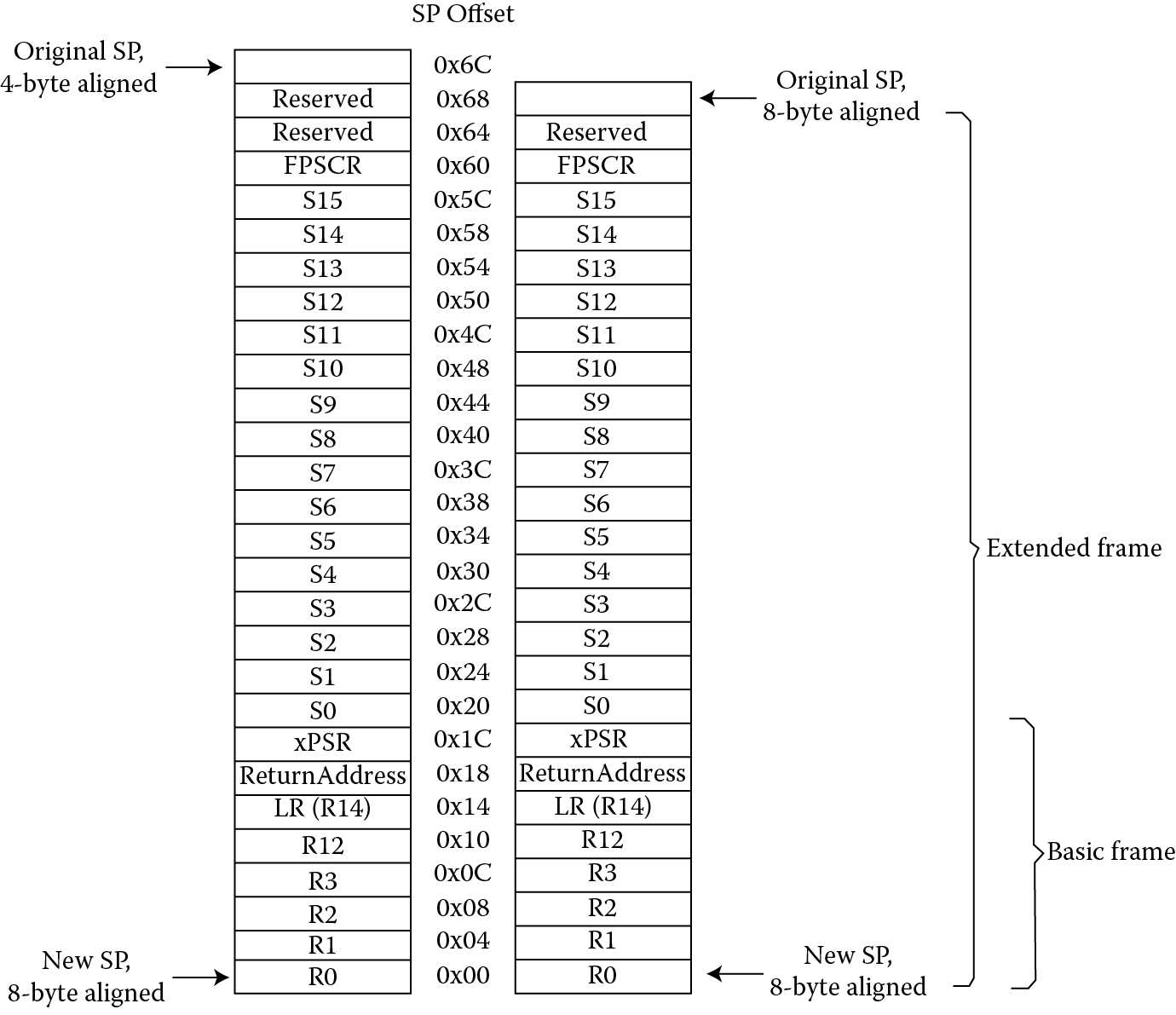
When a processor such as the Cortex-M4 first begins exception processing, eight data words are automatically pushed onto the current stack. This stack frame, as it is called, consists of registers r0 through r3, register r12, the Link Register, the PC, and the contents of the xPSR, shown in Figure 15.4. If a floating-point unit is present and enabled, the Cortex-M4 will also stack the floating-point state. Recall from Section 15.4 that there is an option that controls which stack pointer is used, either the MSP or the PSP, but we’ll continue to use the MSP for our next example.
Example 15.3
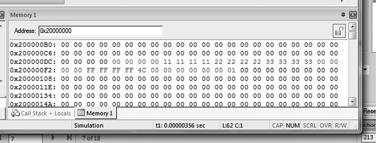
Let’s rerun the code from our last example, which trapped the division by zero. Single-step through the code, up to the point where the processor tries to execute the second (faulting) division. Open a memory window to examine the contents of memory. On the Tiva TM4C1233H6PM microcontroller, SRAM begins at address 0x20000000 and the stack has been defined to be 256 bytes (0x100) at the top of our program. If you look at memory starting just below 0x20000100, you will notice that the contents of registers r0 through r3, register r12, the Link Register, the PC, and the contents of the xPSR have been moved onto the stack, shown in Figure 15.5. Recall that the stack pointer indicates the address of the last full entry, so stacking would begin at address 0x200000FC.
While the processor is storing critical information on the stack, it also reads the address of the exception handler in the vector table. In our previous example, the processor is about to take a usage fault exception, so the address found at memory location 0x00000018 would be used. The processor will also store one more value for us, called EXC_RETURN, in the Link Register. This 32-bit value describes which stack to use upon exception return, as well as the mode from which the processor left before the exception occurred. Table 15.2 shows all the values currently used on the Cortex-M4—most are reserved. Notice also from our previous example that the EXC_RETURN value was 0xFFFFFFF9, since the floating-point unit was not enabled at the time we took the exception, and we wish to return to Thread mode.
EXC_RETURN Value for the Cortex-M4 with Floating-Point Hardware
|
EXC_RETURN[31:0] |
State |
Return to |
Using Stack Pointer |
|
0xFFFFFFE1 |
Floating-point |
Handler mode |
MSP |
|
0xFFFFFFE9 |
Floating-point |
Thread mode |
MSP |
|
0xFFFFFFED |
Floating-point |
Thread mode |
PSP |
|
0xFFFFFFF1 |
Non-floating-point |
Handler mode |
MSP |
|
0xFFFFFFF9 |
Non-floating-point |
Thread mode |
MSP |
|
0xFFFFFFFD |
Non-floating-point |
Thread mode |
PSP |
15.5.2 Exit
Returning from exceptions might be one of the few processes that is easier to do on a Cortex-M4 than on the ARM7TDMI, since the processor does most of the work for us. If we are in Handler mode and we wish to return to the main program, one of the following instructions can be used to load the EXC_RETURN value into the Program Counter:
- A LDR or LDM instruction with the PC as the destination
- A POP instruction that loads the PC
- A BX instruction using any register
As a point of interest, some processors use a dedicated instruction to indicate that an exception is complete, and ARM could have done the same thing given the architectural model of the Cortex-M4. However, the idea is to have a device that you can program entirely in C, so a conventional return instruction is used to allow C subroutines to handle exceptions. Most of the return information is held in the EXC_RETURN value.
15.6 Exception Types
In Chapter 14, we saw the different types of exceptions that ARM processors are asked to handle, and we noted that exceptions require the processor to take some time from normal processing to service a peripheral, deal with an interrupt, or handle a fault of some type. There are even more exception types on the Cortex-M4, some of which are common, some of which are not. In fact, in any given microcontroller application, testing and product development cycles have hopefully removed all of the unexpected conditions so that the processor sees only requests which can be handled easily—interrupts, or possibly a debugger poking around. On the ARM7TDMI, the priorities of the exception types are fixed, so that data aborts overrule interrupts. On version 7-M processors, the exception types are mostly programmable, with a few types being fixed (refer back to Table 15.1): reset (-3 or the highest), non-maskable interrupt (-2), and hard fault (-1). Interrupts will be covered in more detail in Section 15.7.
The following types of exceptions are present on the Cortex-M4:
- Reset
- NMI
- Hard fault
- Memory management fault
- Bus fault
- Usage fault
- SVCall
- Debug monitor
- PendSV
- SysTick
- Interrupt
When the Cortex-M4 processor is reset, it will fetch the value at address 0x0 and address 0x4 (usually located in either Flash memory or some kind of ROM), reading both the initial stack pointer and the reset vector, respectively. As it turns out, there are different ways to reset a system, either parts of it or the entire thing. Depending on what’s needed, a reset handler can be very simple, or it may need to perform tasks such as:
- Enable a floating-point unit
- Initialize the memory system (e.g., if a memory protection unit [MPU] is present)
- Initialize the two stack pointers and all of the registers
- Initialize any critical I/O devices
- Initialize any peripheral registers, control registers, or clocks, such as a phase-locked loop (PLL)
- Enable certain exception types
A non-maskable interrupt (NMI) has the second highest priority among the exceptions, which means that in most cases, when the processor sees the request, it will be handled immediately. There are conditions that might prevent this, such as the processor being halted by the debugger or an NMI handler already running, but otherwise, this exception is permanently enabled and cannot be masked. On the Tiva TM4C1233H6PM, for example, an NMI can be triggered by both hardware and software (there is an Interrupt Control and State Register to do this).
A hard fault can occur when the processor sees an error during exception processing, or when another fault such as a usage fault is disabled. In our example code, if we disable usage faults and then rerun the code, you will notice that the processor takes a hard fault when the UDIV instruction is attempted, rather than a usage fault. You can also see hard faults when there is an attempt to access the System Control Space in an unprivileged mode; for example, if you attempt to write a value to one of the NVIC registers in Thread mode, the processor will take an exception.
Memory management faults occur when the processor attempts to access areas of memory that are inaccessible to the current mode and privilege level (e.g., privileged access only or read only) or that are not defined by the MPU. Generally, the reason for the fault and the faulting address can be found in the Memory Management Fault Status Register, shown in Table 15.3. Like usage and bus faults, memory management faults must also be enabled before the processor can use them.
Memory Management Fault Status Register (Offset 0xD28)
|
Bit |
Name |
Reset Value |
Description |
|
7 |
MMARVALID |
0 |
Indicates the Memory Management Address register is valid |
|
6:5 |
— |
— |
— |
|
4 |
MSTKERR |
0 |
Stacking error |
|
3 |
MUNSTKERR |
0 |
Unstacking error |
|
2 |
— |
— |
— |
|
1 |
DACCVIOL |
0 |
Data access violation |
|
0 |
IACCVIOL |
0 |
Instruction access violation |
One of the busses that commonly runs through a conventional SoC is the AMBA High-Performance Bus (AHB), connecting memory and peripherals to the main processor. Bus faults occur when an error response returns from an access on the AHB bus, either for instruction or data accesses. There is a Fault Status Register for these errors as well, so that an exception handler can determine the offending instruction and possibly recover. Since both precise bus faults (where the fault occurs on the last completed operation) and imprecise bus faults (where the fault is triggered by an instruction that may have already completed) can generate an error, recovery is possible in some cases, but it is certainly not easy to do.
Usage faults occur for a number of reasons. If you have enabled usage faults, then the processor will take an exception for the following:
- Trying to divide by zero, assuming that the processor has been told to trap on this event (i.e., setting the DIV_0_TRP bit in the NVIC as we did in Example 15.1)
- Trying to switch the processor into ARM state. Recall that the least significant bit of branch targets, exception vectors, and PC values popped from the stack must be a 1, since the Cortex-M4 always operates in Thumb state. The INVSTATE bit will be set in the Usage Fault Status Register shown in Table 15.4
- Using an undefined instruction
- Attempting an illegal unaligned access
- Attempting to execute a coprocessor instruction
- Returning from an exception with an invalid EXC_RETURN value
Table 15.4 shows all of the bits in the Usage Fault Status Register that can be examined by a fault handler.
Usage Fault Status Register (Offset 0xD2A)
|
Bit |
Name |
Reset Value |
Description |
|
9 |
DIVBYZERO |
0 |
Indicates a divide by zero has occurred (only if DIV_0_TRP is also set) |
|
8 |
UNALIGNED |
0 |
An unaligned access fault has occurred |
|
7:4 |
— |
— |
— |
|
3 |
NOCP |
0 |
Indicates a coprocessor instruction was attempted |
|
2 |
INVPC |
0 |
An invalid EXC_RETURN value was used in an exception |
|
1 |
INVSTATE |
0 |
An attempt was made to switch to an invalid state |
|
0 |
UNDEFINSTR |
0 |
Processor tried to execute an undefined instruction |
At this point, we might be tempted to clean up our usage fault handler from earlier examples so that the divide-by-zero error is no longer a problem. In an actual system, a warning, an error, or possibly a symbol such as “#DIV/0!” could be printed to a screen, but in an embedded system using only integer math, a division by zero is often catastrophic. There is no recovery that makes sense—what value could you return that either represents infinity or represents a number that could guarantee an algorithm would not exceed certain bounds? Unlike our short examples, a proper usage fault handler should follow the AAPCS guidelines, stacking the appropriate registers before proceeding, and it might even determine the destination register in the offending instruction to make a partial recovery. If an operating system were running, one course of action would be to terminate the thread that generated this exception and perhaps indicate the error to the user.
Supervisor calls (SVCall) and Pendable Service Calls (PendSV) are similar in spirit to the SWI (now SVC) exceptions on the ARM7TDMI, where user-level code can access certain resources in a system, say a particular piece of hardware, by forcing an exception. A handler running in a privileged mode then examines the actual SVC instruction to determine specifically what is being requested. This way, hardware can be controlled by an operating system, and something like an API can be provided to programmers, leaving device drivers to take care of the details. Pending Service Calls can be used in conjunction with SVC instructions to provide efficient handling of context switching for operating systems. See (Yiu 2014) for details on working with service calls and interrupt handling.
The SYSTICK exception is generated by a 24-bit internal timer that is controlled by four registers. When this system timer reaches zero, it can generate an exception with its own vector number (refer back to Table 15.1). Operating systems use this type of timer for task management, that is, to ensure that no single task is allowed to run more than any other. For an excellent reference on operating systems, particularly for embedded systems, see (http://processors.wiki.ti.com/index.php/TI-RTOS_Workshop#Intro_to_TI-RTOS_Kernel_Workshop_Online_Video_Tutorials, 2013).
The last two types of exceptions are almost polar opposites of each other in terms of attention. One, the Debug Monitor exception, is generated by a debug monitor running in a system, and consequently, is of interest to writers of debug monitors and few others (if you are really curious, consult the RealView ICE User Guide (ARM 2008b) for details on working with debug components). The second, interrupts, are used by nearly everyone, and therefore deserves a section of its own.
15.7 Interrupts
In Section 14.2 we saw that not all exceptions are unwanted, particularly interrupts, since peripherals can generate them. The Cortex-M4 supports up to 240 interrupts of the 496 allowed by the Cortex-M specification, although most silicon vendors do not implement all of them. In fact, if we carefully examine the TM4C1233H6PM microcontroller from TI, you will notice that it supports only 65—still, quite a few. The interrupt priorities are also programmable, so that the various interrupts coming from different peripherals can either have the same weighting or unique priorities which are assigned to each one. There are so many variations on the interrupts, in fact, that all of the details are best left for a book like (Yiu 2014) or the Cortex-M4 Technical Reference Manual (ARM 2009). Interrupts can be masked; interrupts can be held pending; interrupts can have subpriorities; and you can disable only interrupts with a priority below a certain level. All of these options are not critical to our understanding of how they work and what is necessary to configure a peripheral to generate one.
Reading through the partial list of peripherals in Table 15.5, you can see that the various peripherals can generate an interrupt, and all of these interrupts are handled and prioritized by the NVIC (also covered in Chapter 14) once it is configured. A full listing can be found in the Data Sheet (Texas Instruments 2013a).
Partial Vector Table for Interrupts on the Tiva TM4C1233H6PM Microcontroller
|
Vector Number |
Interrupt Number (Bit in Interrupt Registers) |
Vector Address or Offset |
Description |
|
0–15 |
— |
0x00000000–0x0000003C |
Processor Exceptions |
|
. |
. |
. |
|
|
. |
. |
. |
|
|
. |
. |
. |
|
|
30 |
14 |
0x00000078 |
ADC0 Sequence 0 |
|
31 |
15 |
0x0000007C |
ADC0 Sequence 1 |
|
32 |
16 |
0x00000080 |
ADC0 Sequence 2 |
|
33 |
17 |
0x00000084 |
ADC0 Sequence 3 |
|
34 |
18 |
0x00000088 |
Watchdog Timers 0 and 1 |
|
35 |
19 |
0x0000008C |
16/32-Bit Timer 0A |
|
36 |
20 |
0x00000090 |
16/32-Bit Timer 0B |
|
37 |
21 |
0x00000094 |
16/32-Bit Timer 1A |
|
38 |
22 |
0x00000098 |
16/32-Bit Timer 1B |
|
37 |
21 |
0x0000009C |
16/32-Bit Timer 2A |
|
38 |
22 |
0x000000A0 |
16/32-Bit Timer 2B |
|
. |
. |
. |
|
|
. |
. |
. |
|
|
. |
. |
. |
|
|
51 |
35 |
0x000000CC |
16/32-Bit Timer 3A |
|
52 |
36 |
0x000000D0 |
16/32-Bit Timer 3B |
|
. |
. |
. |
Configuration is probably the least trivial aspect of working with a microcontroller the size of the TM4C1233H6PM. There are dozens of registers than may need to be configured in any given system. Consequently, silicon vendors provide their own APIs to use when programming the controllers in a language like C. The libraries are based around the Cortex Microcontroller Software Interface Standard (CMSIS) from ARM. TivaWareTM from Texas Instruments and the LPCOpen Platform from NXP are examples of libraries that allow peripherals to be enabled and configured using only standard access functions. To fully appreciate a statement like
SysCtlPeripheralEnable(SYSCTL_PERIPH_TIMER0);
you need to program the same operation in assembly at least once! That’s where we begin.
Example 15.4
Let’s look at an example of a relatively simple interrupt being caused by a timer counting down to zero. You can see from Table 15.5 that the twelve timers are all given their own vector number, interrupt number, and vector address. We’ll set up one 16-bit timer, Timer 0A, to count down from 0xFFFF to 0, sending an interrupt to the NVIC, alerting the core that the timer expired. The processor will acknowledge the interrupt and jump to a handler routine. Once inside the interrupt handler, we’ll put a value into a core register and then spin in an infinite loop so that we can see the process happen using a debugger. In this example, we’ll use the Tiva Launchpad as a target. As a necessity, the timer must be configured as a memory-mapped peripheral, but this gives us a preview of Chapter 16.
In order to configure the interrupts, the following must take place:
- The system clocks on processor must be set up, similar to the code we’ll use in Chapter 16 for the GPIO example.
- The clocks must be enabled to the interrupt block, specifically, using the RCGCTIMER register. Now that the timer is enabled, we can actually write to the memory-mapped registers within it. If the interrupt block is not enabled, any attempts to write to the memory-mapped registers results in a hard fault.
- Rather than having a periodic timer, we will configure it to be a one-shot timer. To do this, we must configure the GPTMTnMR register.
- The timer will be set up as a 16-bit timer, so the initial count will be (by a reset) set to 0xFFFF. By default, the timer will count down to zero, rather than up.
- The interrupt from the timer needs to be enabled. There is a GPTMIMR register, or General-Purpose Timer Interrupt Mask Register, than needs to be configured. Writing a 1 to the appropriate bit enables the interrupt.
- Interrupts needs to be enabled from Timer 0A in the NVIC. Bit 19 of the Interrupt Set Enable register in the NVIC enables Timer 0A.
- The timer needs to be started.
Using the Code Composer Studio tools, you can create a source code file with the following code:
MOVW r0, #0xE000
MOVT r0, #0x400F
MOVW r2, #0x60 ; offset 0x060 for this register
MOVW r1, #0x0540
MOVT r1, #0x01C0
STR r1, [r0, r2] ; write the register’s content
MOVW r7, #0x604 ; enable timer0 - RCGCTIMER
LDR r1, [r0, r7] ; p. 321, base 0x400FE000
ORR r1, #0x1 ; offset - 0x604
STR r1, [r0, r7] ; bit 0
NOP
NOP
NOP
NOP
NOP ; give myself 5 clocks per spec
MOVW r8, #0x0000 ; configure timer0 to be
MOVT r8, #0x4003 ; one-shot, p.698 GPTMTnMR
MOVW r7, #0x4 ; base 0x40030000
LDR r1, [r8, r7] ; offset 0x4
ORR r1, #0x21 ; bit 5 = 1, 1:0 = 0x1
STR r1, [r8, r7]
LDR r1, [r8] ; set as 16-bit timer only
ORR r1, #0x4 ; base 0x40030000
STR r1, [r8] ; offset 0, bit[2:0] = 0x4
MOVW r7, #0x30 ; set the match value at 0
MOV r1, #0 ; since we’re counting down
STR r1, [r8, r7] ; offset - 0x30
MOVW r7, #0x18 ; set bits in the GPTM
LDR r1, [r8, r7] ; Interrupt Mask Register
ORR r1, #0x10 ; p. 714 - base: 0x40030000
STR r1, [r8, r7] ; offset - 0x18, bit 5
MOVW r6, #0xE000 ; enable interrupt on timer0
MOVT r6, #0xE000 ; p. 132, base 0xE000E000
MOVW r7, #0x100 ; offset - 0x100, bit 19
MOV r1, #(1 < <19) ; enable bit 19 for timer0
STR r1, [r6, r7]
MOVW r6, #0x0000 ; start the timer
MOVT r6, #0x4003
MOVW r7, #0xC
LDR r1, [r6, r7]
ORR r1, #0x1
STR r1, [r6, r7] ; go!!
Now that the NVIC, Timer 0A, and all of the control registers are programmed, we can write a very simple handler for the interrupt we are expecting:
IntDefaultHandler:
MOVW r10, #0xBEEF
MOVT r10, #0xDEAD
Spot
B Spot
This will do nothing more than write a value into register r10 and then spin in a loop.
To run this program on a Tiva Launchpad, you will likely have to reset the system after the code is loaded (as opposed to resetting just the core). Then run the program. Once you hit the stop button, you can see that the processor is in the interrupt handler just executing branch instructions in a loop. The entire program is given in Appendix D.
15.8 Exercises
- How many operation modes does the Cortex-M4 have?
- What happens if you do not enable usage faults in Example 15.1?
- Which register must be used to switch privilege levels?
- What are the differences between the ARM7TDMI and Cortex-M4 vector tables?
- Give the offsets (from the base address 0xE000E000) and register size for the following:
- Usage Fault Status Register
- Memory Management Fault Status Register
- You may wish to consult the TM4C1233H6PM data sheet (Texas Instruments 2013b).
- Configure Example 15.4 so that the timer counts up rather than down. Don’t forget to configure the appropriate match value!