Table of Contents for
ARM Assembly Language, 2nd Edition
 ARM Assembly Language, 2nd Edition
Published by
Chapman and Hall/CRC, 2016
ARM Assembly Language, 2nd Edition
Published by
Chapman and Hall/CRC, 2016
- Contents
- ARM Assembly Language: Fundamentals and Techniques, Second Edition
- Preliminaries
- To our families
- Preface
- Acknowledgments
- Authors
- Chapter 1 - An Overview of Computing Systems
- Chapter 2 - The Programmer’s Model
- Chapter 3 - Introduction to Instruction Sets: v4T and v7-M
- Chapter 4 - Assembler Rules and Directives
- Chapter 5 - Loads, Stores, and Addressing
- Chapter 6 - Constants and Literal Pools
- Chapter 7 - Integer Logic and Arithmetic
- Chapter 8 - Branches and Loops
- Chapter 9 - Introduction to Floating-Point: Basics, Data Types, and Data Transfer
- Chapter 10 - Introduction to Floating-Point: Rounding and Exceptions
- Chapter 11 - Floating-Point Data-Processing Instructions
- Chapter 12 - Tables
- Chapter 13 - Subroutines and Stacks
- Chapter 14 - Exception Handling: ARM7TDMI
- Chapter 15 - Exception Handling: v7-M
- Chapter 16 - Memory-Mapped Peripherals
- Chapter 17 - ARM, Thumb and Thumb-2 Instructions
- Chapter 18 - Mixing C and Assembly
- Appendix A: Running Code Composer Studio
- Appendix B: Running Keil Tools
- Appendix C: ASCII Character Codes
- Appendix D
- Glossary
- References
Chapter 2
The Programmer’s Model
2.1 Introduction
All microprocessors have a set of features that programmers use. In most instances, a programmer will not need an understanding of how the processor is actually constructed, meaning that the wires, transistors, and/or logic boards that were used to build the machine are not typically known. From a programmer’s perspective, what is necessary is a model of the device, something that describes not only the way the processor is controlled but also the features available to you from a high level, such as where data can be stored, what happens when you give the machine an invalid instruction, where your registers are stacked during an exception, and so forth. This description is called the programmer’s model. We’ll begin by examining the basic parts of the ARM7TDMI and Cortex-M4 programmer’s models, but come back to certain elements of them again in Chapters 8, 13, 14, and 15, where we cover branching, stacks, and exceptions in more detail. For now, a brief treatment of the topic will provide some definition, just enough to let us begin writing programs.
2.2 Data Types
Data in machines is represented as binary digits, or bits, where one binary digit can be seen as either on or off, a one or a zero. A collection of bits are often grouped together into units of eight, called bytes, or larger units whose sizes depend on the maker of the device, oddly enough. For example, a 16-bit data value for a processor such as the Intel 8086 or MC68040 is called a word, where a 32-bit data value is a word for the ARM cores. When describing both instructions and data, normally the length is factored in, so that we often speak of 16-bit instructions or 32-bit instructions, 8-bit data or 16-bit data, etc. Specifically for data, the ARM7TDMI and Cortex-M4 processors support the following data types:
Byte, or 8 bits
Halfword, or 16 bits
Word, or 32 bits
For the moment, the length of the instructions is immaterial, but we’ll see later than they can be either 16 or 32 bits long, so you will need two bytes to create a Thumb instruction and four bytes to create either an ARM instruction or a Thumb-2 instruction. For the ARM7TDMI, when reading or writing data, halfwords must be aligned to two-byte boundaries, which means that the address in memory must end in an even number. Words must be aligned to four-byte boundaries, i.e., addresses ending in 0, 4, 8, or C. The Cortex-M4 allows unaligned accesses under certain conditions, so it is actually possible to read or write a word of data located at an odd address. Don’t worry, we’ll cover memory accesses in much more detail when we get to addressing modes in Chapter 5. Most data operations, e.g., ADD, are performed on word quantities, but we’ll also work with smaller, 16-bit values later on.
2.3 ARM7TDMI
The motivation behind examining an older programmer’s model is to show its similarity to the more advanced cores—the Cortex-A and Cortex-R processors, for example, look very much like the ARM7TDMI, only with myriad new features and more modes, but everything here applies. Even though the ARM7TDMI appears simple (only three stages in its pipeline) when compared against the brobdingnagian Cortex-A15 (highly out-of-order pipeline with fifteen stages), there are still enough details to warrant a more cautious introduction to modes and exceptions, omitting some details for now. It is also noteworthy to point out features that are common to all ARM processors but differ by number, use, and limitations, for example, the size of the integer register file on the Cortex-M4. The registers look and act the same as those on an ARM7TDMI, but there are just fewer of them. Our tour of the programmer’s model starts with the processor modes.
2.3.1 Processor Modes
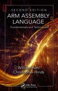
Version 4T cores support seven processor modes: User, FIQ, IRQ, Supervisor, Abort, Undefined, and System, as shown in Figure 2.1. It is possible to make mode changes under software control, but most are normally caused by external conditions or exceptions. Most application programs will execute in User mode. The other modes are known as privileged modes, and they provide a way to service exceptions or to access protected resources, such as bits that disable sections of the core, e.g., a branch predictor or the caches, should the processor have either of these.
A simple way to look at this is to view a mode as an indication of what the processor is actually doing. Under normal circumstances, the machine will probably be in either User mode or Supervisor mode, happily executing code. Consider a device such as a cell phone, where not much happens (aside from polling) until either a signal comes in or the user has pressed a key. Until that time, the processor has probably powered itself down to some degree, waiting for an event to wake it again, and these external events could be seen as interrupts. Processors generally have differing numbers of interrupts, but the ARM7TDMI has two types: a fast interrupt and a lower priority interrupt. Consequently, there are two modes to reflect activities around them: FIQ mode and IRQ mode. Think of the fast interrupt as one that might be used to indicate that the machine is about to lose power in a few milliseconds! Lower priority interrupts might be used for indicating that a peripheral needs to be serviced, a user has touched a screen, or a mouse has been moved.
Abort mode allows the processor to recover from exceptional conditions such as a memory access to an address that doesn’t physically exist, for either an instruction or data. This mode can also be used to support virtual memory systems, often a requirement of operating systems such as Linux. The processor will switch to Undefined mode when it sees an instruction in the pipeline that it does not recognize; it is now the programmer’s (or the operating system’s) responsibility to determine how the machine should recover from such as error. Historically, this mode could be used to support valid floating-point instructions on machines without actual floating-point hardware; however, modern systems rarely rely on Undefined mode for such support, if at all. For the most part, our efforts will focus on working in either User mode or Supervisor mode, with special attention paid to interrupts and other exceptions in Chapter 14.
2.3.2 Registers
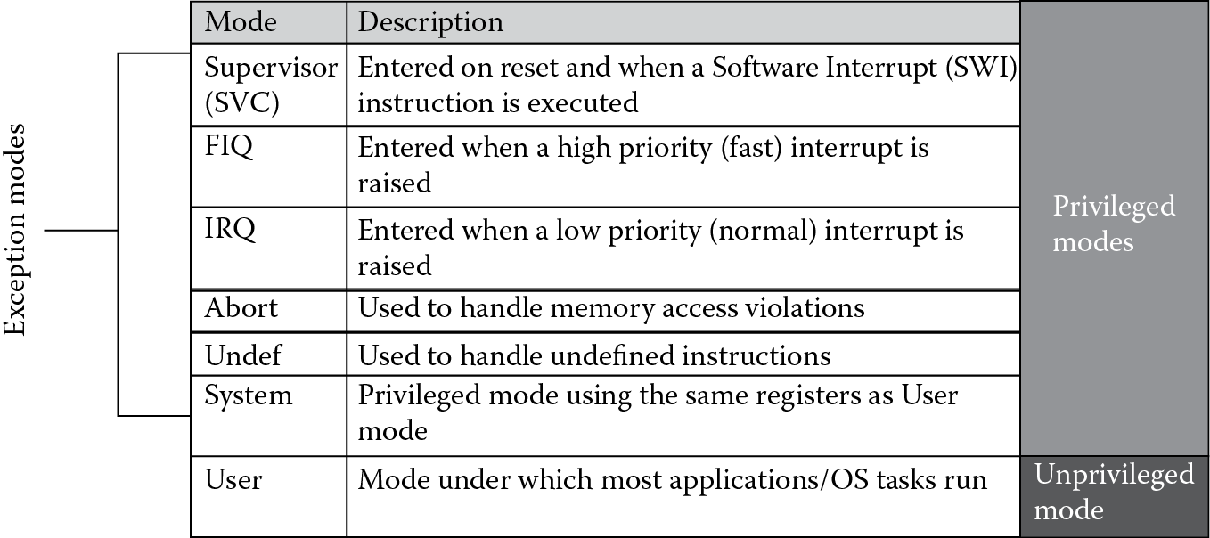
The register is the most fundamental storage area on the chip. You can put most anything you like in one—data values, such as a timer value, a counter, or a coefficient for an FIR filter; or addresses, such as the address of a list, a table, or a stack in memory. Some registers are used for specific purposes. The ARM7TDMI processor has a total of 37 registers, shown in Figure 2.2. They include
- 30 general-purpose registers, i.e., registers which can hold any value
- 6 status registers
- A Program Counter register
The general-purpose registers are 32 bits wide, and are named r0, r1, etc. The registers are arranged in partially overlapping banks, meaning that you as a programmer see a different register bank for each processor mode. This is a source of confusion sometimes, but it shouldn’t be. At any one time, 15 general-purpose registers (r0 to r14), one or two status registers, and the Program Counter (PC or r15) are visible. You always call the registers the same thing, but depending on which mode you are in, you are simply looking at different registers. Looking at Figure 2.2, you can see that in User/System mode, you have registers r0 to r14, a Program Counter, and a Current Program Status Register (CPSR) available to you. If the processor were to suddenly change to Abort mode for whatever reason, it would swap, or bank out, registers r13 and r14 with different r13 and r14 registers. Notice that the largest number of registers swapped occurs when the processor changes to FIQ mode. The reason becomes apparent when you consider what the processor is trying to do very quickly: save the state of the machine. During an interrupt, it is normally necessary to drop everything you’re doing and begin to work on one task: namely, saving the state of the machine and transition to handling the interrupt code quickly. Rather than moving data from all the registers on the processor to external memory, the machine simply swaps certain registers with new ones to allow the programmer access to fresh registers. This may seem a bit unusual until we come to the chapter on exception handling. The banked registers are shaded in the diagram.
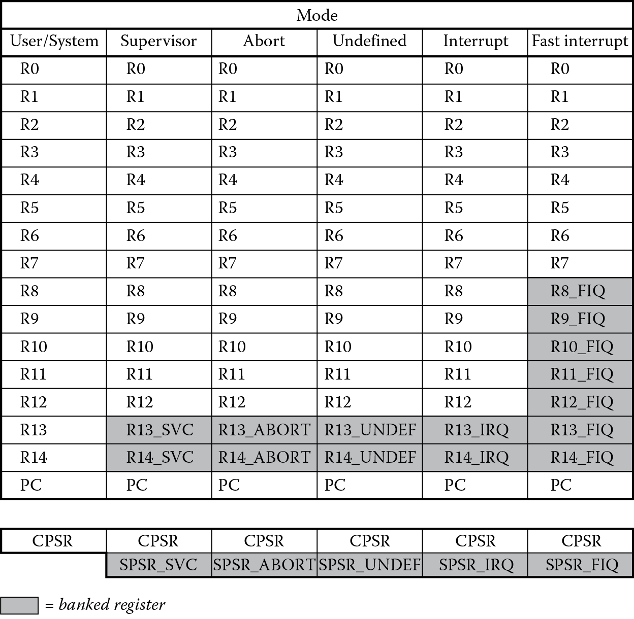
While most of the registers can be used for any purpose, there are a few registers that are normally reserved for special uses. Register r13 (the stack pointer or SP) holds the address of the stack in memory, and a unique stack pointer exists in each mode (except System mode which shares the User mode stack pointer). We’ll examine this register much more in Chapter 13. Register r14 (the Link Register or LR) is used to hold subroutine and exception return addresses. As with the stack pointers, a unique r14 exists in all modes (except System mode which shares the User mode r14). In Chapters 8 and 13, we will begin to work with branches and subroutines, and this register will hold the address to which we need to return should our program jump to a small routine or a new address in memory. Register r15 holds the Program Counter (PC). The ARM7TDMI is a pipelined architecture, as shown in Figure 2.3, meaning that while one instruction is being fetched, another is being decoded, and yet another is being executed. The address of the instruction that is being fetched (not the one being executed) is contained in the Program Counter. This register is not normally accessed by the programmer unless certain specific actions are needed, such as jumping long distances in memory or recovering from an exception. You can read a thorough treatment of pipelined architectures in Patterson and Hennessy (2007).
The Current Program Status Register (CPSR) can be seen as the state of the machine, allowing programs to recover from exceptions or branch on the results of an operation. It contains condition code flags, interrupt enable flags, the current mode, and the current state (more on the differences between ARM and Thumb state is discussed in Chapter 17). Each privileged mode (except System mode) has a Saved Program Status Register (SPSR) that is used to preserve the value of the CPSR when an exception occurs. Since User mode and System mode are not entered on any exception, they do not have an SPSR, and a register to preserve the CPSR is not required. In User mode or System mode, if you attempt to read the SPSR, you will get an unpredictable value back, meaning the data cannot be used in any further operations. If you attempt to write to the SPSR in one of these modes, the data will be ignored.
The format of the Current Program Status Register and the Saved Program Status Register is shown in Figure 2.4. You can see that it contains four bits at the top, collectively known as the condition code flags, and eight bits at the bottom. The condition code flags in the CPSR can be altered by arithmetic and logical instructions, such as subtractions, logical shifts, and rotations. Furthermore, by allowing these bits to be used with all the instructions on the ARM7TDMI, the processor can conditionally execute an instruction, providing improvements in code density and speed. Conditional execution and branching are covered in detail in Chapter 8.
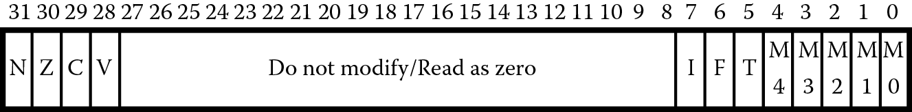
The bottom eight bits of a status register (the mode bits M[4:0], I, F, and T) are known as the control bits. The I and F bits are the interrupt disable bits, which disable interrupts in the processor if they are set. The I bit controls the IRQ interrupts, and the F bit controls the FIQ interrupts. The T bit is a status bit, meant only to indicate the state of the machine, so as a programmer you would only read this bit, not write to it. If the bit is set to 1, the core is executing Thumb code, which consists of 16-bit instructions. The processor changes between ARM and Thumb state via a special instruction that we’ll examine much later on. Note that these control bits can be altered by software only when the processor is in a privileged mode.
Table 2.1 shows the interpretation of the least significant bits in the PSRs, which determine the mode in which the processor operates. Note that while there are five bits that determine the processor’s mode, not all of the configurations are valid (there’s a historical reason behind this). If any value not listed here is programmed into the mode bits, the result is unpredictable, which by ARM’s definition means that the fields do not contain valid data, and a value may vary from moment to moment, instruction to instruction, and implementation to implementation.
The Mode Bits
|
xPSR[4:0] |
Mode |
|
10000 |
User mode |
|
10001 |
FIQ mode |
|
10010 |
IRQ mode |
|
10011 |
Supervisor mode |
|
10111 |
Abort mode |
|
11011 |
Undefined mode |
|
11111 |
System mode |
2.3.3 The Vector Table
There is one last component of the programmer’s model that is common in nearly all processors—the vector table, shown in Table 2.2. While it is presented here for reference, there is actually only one part of it that’s needed for the introductory work in the next few chapters. The exception vector table consists of designated addresses in external memory that hold information necessary to handle an exception, an interrupt, or other atypical event such as a reset. For example, when an interrupt (IRQ) comes along, the processor will change the Program Counter to 0x18 and begin fetching instructions from there. The data values that are located at these addresses are actual ARM instructions, so the next instruction that the machine will likely fetch is a branch (B) instruction, assuming the programmer put such an instruction at address 0x18. Once this branch instruction is executed, the processor will begin fetching instructions for the interrupt handler that resides at the target address, also specified with the branch instruction, somewhere in memory. It is worth noting here that many processors, including the Cortex-M4, have addresses at these vector locations in memory. The ARM7TDMI processor places instructions here. You can use the fact that instructions reside at these vectors for a clever shortcut, but it will have to wait until Chapter 14.
ARM7TDMI Exception Vectors
|
Exception Type |
Mode |
Vector Address |
|
Reset |
SVC |
0x00000000 |
|
Undefined instruction |
UNDEF |
0x00000004 |
|
Software Interrupt (SVC) |
SVC |
0x00000008 |
|
Prefetch abort (instruction fetch memory abort) |
ABORT |
0x0000000C |
|
Data abort (data access memory abort) |
ABORT |
0x00000010 |
|
IRQ (interrupt) |
IRQ |
0x00000018 |
|
FIQ (fast interrupt) |
FIQ |
0x0000001C |
The one exception vector with which we do need to concern ourselves before writing some code is the Reset exception vector, which is at address 0x0 in memory. Since the machine will fetch from this address immediately as it comes out of reset, we either need to provide a reset exception handler (to provide an initialization routine for turning on parts of the device and setting bits the way we like) or we can begin coding at this address, assuming we have a rather unusual system with no errors, exceptions, or interrupts. Many modern development tools provide a startup file for specific microcontrollers, complete with startup code, initialization routines, exception vector assignments, etc., so that when we begin programming, the first instruction in your code isn’t really the first instruction the machine executes. However, to concentrate on the simpler instructions, we will bend the rules a bit and ignore exceptional conditions for the time being.
2.4 Cortex-M4
The Cortex-M family differs significantly from earlier ARM designs, but the programmer’s model is remarkably similar. The cores are very small. They may only implement a subset of instructions. The memory models are relatively simple. In some ways the Cortex-M3 and M4 processors resemble much older microcontrollers used in the 1970s and 1980s, and the nod to these earlier designs is justified by the markets that they target. These cores are designed to be used in applications that require 32-bit processors to achieve high code density, fast interrupt response times, and now even the ability to handle signal processing algorithms, but the final product produced by silicon vendors may cost only a few dollars. The line between the world of microcontrollers and the world of high-end microprocessors is beginning to blur a bit, as we see features like IEEE floating-point units, real-time operating system support, and advanced trace capabilities in an inexpensive device like the Tiva microcontrollers from TI. There is no substitute for actually writing code, so for now, we will learn enough detail of the programmer’s model to bring the processor out of reset, play with some of the registers in the Cortex-M4 and its floating-point unit, and then stop a simulation. Again, we begin with the processor modes.
2.4.1 Processor Modes
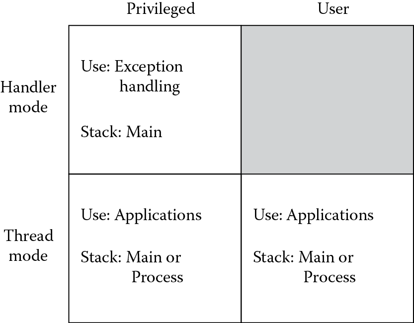
The Cortex-M4 has only two modes: Handler mode and Thread mode. As shown in Figure 2.5, there are also two access levels to go along with the modes, Privileged and User, and depending on what the system is doing, it will switch between the two using a bit in the CONTROL register. For very simple applications, the processor may only stay in a single access level—there might not be any User-level code running at all. In situations where you have an embedded operating system, such as SYS/BIOS controlling everything, security may play a role by partitioning the kernel’s stack memory from any user stack memory to avoid problems. In Chapter 15, we will examine the way the Cortex-M4 handles exceptions more closely.
2.4.2 Registers
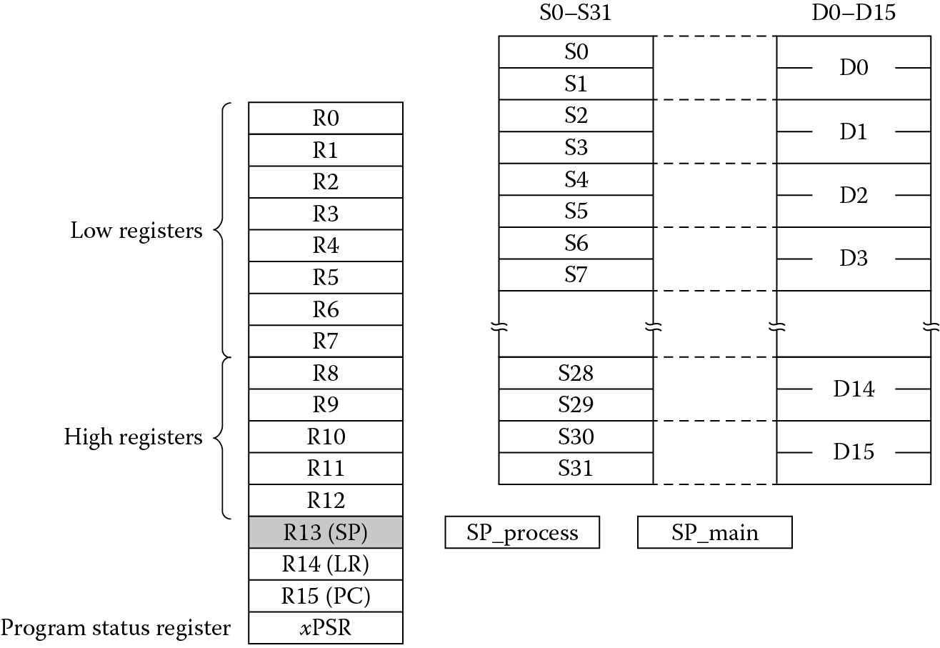
There appear to be far fewer physical registers on a Cortex-M4 than an ARM7TDMI, as shown in Figure 2.6, but the same 16 registers appear as those in User mode on the ARM7TDMI. If you have a Cortex-M4 that includes a floating-point unit, there are actually more. Excluding peripherals, the Cortex-M4 with floating-point hardware contains the following registers as part of the programmer’s model:
- 17 general purpose registers, i.e., registers than can hold any value
- A status register than can be viewed in its entirety or in three specialized views
- 3 interrupt mask registers
- A control register
- 32 single-precision floating-point registers (s0–s31) or 16 double-precision registers (d0–d15) or a mix
- 4 floating-point control registers (although these are memory-mapped, not physical registers)
As described in the previous section, registers r0 through r12 are general purpose registers, and the registers hold 32-bit values that can be anything you like—addresses, data, packed data, fractional data values, anything. There are some special purpose registers, such as register r13, the stack pointer (and there are two of them, giving you the ability to work with separate stacks); register r14, the Link Register; and register r15, which is the Program Counter. Like the ARM7TDMI, register r13 (the stack pointer or SP) holds the address of the stack in memory, only there are just two of them in the Cortex-M4, the Main Stack Pointer (MSP) and the Process Stack Pointer (PSP). We’ll examine these registers much more in Chapter 15. Register r14 (the Link Register or LR) is used to hold subroutine and exception return addresses. Unlike the ARM7TDMI, there is only one Link Register. Register r15, the Program Counter or PC, points to the instruction being fetched, but due to pipelining, there are enough corner cases to make hard and fast rules about its value difficult, so details can be safely tabled for now.
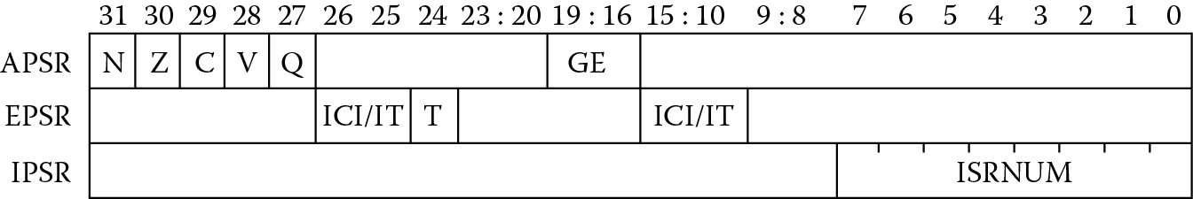
The Program Status Register, or xPSR, performs the same function that the ARM7TDMI’s CPSR does, but with different fields. The entire register can be accessed all at once, or you can examine it in three different ways, as shown in Figure 2.7. The Application Program Status Register (APSR), the Interrupt Program Status Register (IPSR), and the Execution Program Status Register (EPSR) are just three specialized views of the same register. The APSR contains the status flags (N, C, V, and Z), the Greater Than or Equal flags (used by the SEL instruction), and an additional “sticky” Q flag used in saturation arithmetic, where sticky in this case means that the bit can only be cleared by explicitly writing a zero to it. The IPSR contains only an exception number that is used in handling faults and other types of exceptions. Two fields contain the IF-THEN instruction status bits overlapped with the Interrupt-Continuable Instruction (ICI) bits, and when combined with the Thumb (T) bit, produce the EPSR. The IF-THEN instruction will be seen when we begin loops and conditional execution in Chapter 8; however, the ICI/IT bits are used for recovering from exceptions, which will not be covered. See the ARM Cortex-M4 Devices Generic User Guide (ARM 2010b) for more details.
The interrupt mask registers, PRIMASK, FAULTMASK, and BASEPRI are use to mask certain types of interrupts and exceptions. PRIMASK and FAULTMASK are actually just single-bit registers. BASEPRI can be up to eight bits wide, and the value contained in this register sets the priority level of allowable interrupts that the processor will acknowledge. In Chapter 15, we’ll see examples of interrupt handling, but for more complex interrupt situations, see Yiu (2014), where the use of interrupt mask registers is illustrated in more detail.
The last special purpose register is the CONTROL register, which consists of only three bits. The least significant bit, CONTROL[0], changes the access level while in Thread mode to either a Privileged or User level. The next most significant bit, CONTROL[1], selects which stack the processor is to use, either the Main Stack Pointer (MSP) or the Process Stack Pointer (PSP). The most significant bit, CONTROL[2], indicates whether or not to preserve the floating-point state during exception processing. We’ll work with this register a bit more in Chapter 15.
2.4.3 The Vector Table
The Cortex-M4 vector table is probably one of the larger departures from all previous ARM processor designs. Returning to the idea that addresses are stored in the vector table, rather than instructions, the Cortex-M model looks very much like older microcontrollers such as the 8051 and MC6800 in this respect. From Table 2.3, you can see how the various exception types have their own type number and address in memory. An important point here, not normally too prominent if you are coding in C, since a compiler will take care of this issue for you, is that the least significant bit of these exception vectors (addresses) should be set to a 1. When we cover instructions over the next few chapters, we’ll discover that the Cortex-M4 only executes Thumb-2 instructions, rather than ARM instructions as the ARM7TDMI does, and the protocol requires it. This vector table is relocatable after the processor comes out of reset; however, our focus for now is to write short blocks of code without any exceptions or errors, covering procedural details first and worrying about all of the variations later.
Cortex-M4 Exception Vectors
|
Exception Type |
Exception No. |
Vector Address |
|
(Top of Stack) |
— |
0x00000000 |
|
Reset |
1 |
0x00000004 |
|
NMI |
2 |
0x00000008 |
|
Hard fault |
3 |
0x0000000C |
|
Memory management fault |
4 |
0x00000010 |
|
Bus fault |
5 |
0x00000014 |
|
Usage fault |
6 |
0x00000018 |
|
SVcall |
11 |
0x0000002C |
|
Debug monitor |
12 |
0x00000030 |
|
PendSV |
14 |
0x00000038 |
|
SysTick |
15 |
0x0000003C |
|
Interrupts |
16 and above |
0x00000040 and above |
2.5 Exercises
- How many modes does the ARM7TDMI processor have? How many states does it have? How many modes does the Cortex-M4 have?
- What do you think would happen if the instruction SMULTT (an instruction that runs fine on a Cortex-M4) were issued to an ARM7TDMI? Which mode do you think it would be in after this instruction entered the execute stage of its pipeline?
- What is the standard use of register r14? Register r13? Register r15?
- On an ARM7TDMI, in any given mode, how many registers does a programmer see at one time?
- Which bits of the ARM7TDMI status registers contain the flags? Which register on the Cortex-M4 holds the status flags?
- If an ARM7TDMI processor encounters an undefined instruction, from what address will it begin fetching instructions after it changes to Undefined mode? What about a reset?
- What is the purpose of FIQ mode?
- Which mode on an ARM7TDMI can assist in supporting operating systems, especially for supporting virtual memory systems?
- How do you enable interrupts on the ARM7TDMI?
- How many stages does the ARM7TDMI pipeline have? Name them.
- Suppose that the Program Counter, register r15, contained the hex value 0x8000. From what address would an ARM7TDMI fetch an instruction (assume you are in ARM state)?
- What is the function of the Saved Program Status Register?
- On an ARM7TDMI, is it permitted to put the instruction
SUB r0, r2, r3
- at address 0x4? How about at address 0x0? Can you put that same bit pattern at address 0x4 in a system using a Cortex-M4?
- Describe the exception vector table for any other microprocessor. How does it differ from the ARM7TDMI processor? How does it differ from the Cortex-M4?
- Give an example of an instruction that would typically be placed at address 0x0 on an ARM7TDMI. What value is typically placed at address 0x0 on a Cortex-M4?
- Explain the current program state of an ARM7TDMI if the CPSR had the value 0xF00000D3.