Table of Contents for
ARM Assembly Language, 2nd Edition
 ARM Assembly Language, 2nd Edition
Published by
Chapman and Hall/CRC, 2016
ARM Assembly Language, 2nd Edition
Published by
Chapman and Hall/CRC, 2016
- Contents
- ARM Assembly Language: Fundamentals and Techniques, Second Edition
- Preliminaries
- To our families
- Preface
- Acknowledgments
- Authors
- Chapter 1 - An Overview of Computing Systems
- Chapter 2 - The Programmer’s Model
- Chapter 3 - Introduction to Instruction Sets: v4T and v7-M
- Chapter 4 - Assembler Rules and Directives
- Chapter 5 - Loads, Stores, and Addressing
- Chapter 6 - Constants and Literal Pools
- Chapter 7 - Integer Logic and Arithmetic
- Chapter 8 - Branches and Loops
- Chapter 9 - Introduction to Floating-Point: Basics, Data Types, and Data Transfer
- Chapter 10 - Introduction to Floating-Point: Rounding and Exceptions
- Chapter 11 - Floating-Point Data-Processing Instructions
- Chapter 12 - Tables
- Chapter 13 - Subroutines and Stacks
- Chapter 14 - Exception Handling: ARM7TDMI
- Chapter 15 - Exception Handling: v7-M
- Chapter 16 - Memory-Mapped Peripherals
- Chapter 17 - ARM, Thumb and Thumb-2 Instructions
- Chapter 18 - Mixing C and Assembly
- Appendix A: Running Code Composer Studio
- Appendix B: Running Keil Tools
- Appendix C: ASCII Character Codes
- Appendix D
- Glossary
- References
Chapter 8
Branches and Loops
8.1 Introduction
Branches are a necessary evil. Software cannot avoid using them, and hardware engineers treat them as anathema. So much so that computer architects will go to extreme lengths to get rid of them. In fact, researchers spend years and years trying to come up with new strategies to either predict their effects before they arrive or avoid them entirely. A quick read through most computer architecture literature will highlight the elaborate hardware that is included with every modern design: static branch predictors, dynamic branch predictors, two-level adaptive branch predictors, instruction trace caches—the research continues. Certainly, ARM is no stranger to the phenomenon. However, the whole notion of how to remove and predict branches is beyond the scope of this book, so for now, we’re going to examine one way around even having to use a branch instruction in assembly code. In our discussion, the use of conditional execution will demonstrate that even though you can’t remove them completely, some branches can be avoided or removed. While the concepts underlying the ability to change the flow of a program are identical for both A- and M-class processors, the details are sufficiently different to warrant separate discussions. We’ll examine the ARM7TDMI first, then look at some of the new instructions that were made available for the v7-M processors.
8.2 Branching
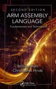
One way to see the effects of a branch in an instruction stream, and the reason they present obstacles to optimizing code, is to look at a pipeline diagram for the ARM7TDMI, shown in Figure 8.1. The three-stage pipeline can fetch one instruction from memory, decode another instruction, and execute a third instruction, all in the same clock cycle. The analogy for a pipeline is washing dishes—one man washes a plate, one man rinses the plate previously washed, and a third man dries the plate previously rinsed, all at the same time. Once a man is finished, he passes his item to the next person in line; each man stays busy doing his task until all the dishes are done. You can see from the diagram that an ADD, SUB, and MOV instruction presents no problems for a pipelined architecture, since there is nothing present that would cause an instruction to stall or force the processor to wait for it to complete. However, a BL instruction, or any other type of branch, will cause the entire pipeline to be flushed—a branch instruction effectively tells the machine to start fetching new instructions from a different address in memory.
From the diagram, you can see that in cycle 1, the branch (BL) has entered the Execute stage of the pipeline, and two instructions have already been fetched (one from address 0x8004 and one from 0x8008). Since the branch says to begin fetching new instructions from address 0x8FEC, those unused instructions must be thrown away. In a three-stage pipeline, the effects are not nearly as deleterious, but consider what would happen in a very deep pipeline, say 24 stages—a branch that is not handled correctly could force the processor to abandon significant amounts of work. It’s worth noting at this point what’s happening in cycles 2 and 3. Since the branch and link instruction saves a return address for us in the Link Register, the processor takes the Program Counter and moves it into register r14. However, we’ve already noted that the Program Counter points to the instruction being fetched in any given cycle, so at the time that the BL instruction is in the execute stage of the pipeline, the Program Counter is pointing to 0x8008. In cycle 2, this value is moved into the Link Register, but notice that we really need to return to address 0x8004. To correct for this, the processor subtracts four from the value in the Link Register in cycle 3 without introducing any stalls in the pipeline.
8.2.1 Branching (ARM7TDMI)
Any event that modifies the Program Counter (register r15) can be defined as a change of flow, and this can be accomplished by either explicitly modifying the Program Counter by writing to it or using one of the branch instructions. The three types of branch instructions on the ARM7TDMI are:
- B—Branch. This is the simplest form of branch, where condition codes may also be used to decide whether or not to branch to a new address in the code.
- BX—Branch indirect (formerly called Branch and eXchange). In addition to providing a branch using a registered value, this instruction provides a mechanism to switch from 32-bit ARM instructions to 16-bit Thumb instructions. We will cover Thumb in more detail in Chapter 17.
- BL—Branch and Link. Here, the Link Register (r14) is used to hold a return address just after a branch instruction, so that if we want to execute a subroutine and return, the processor merely has to put the value of the Link Register into the Program Counter at the end of the subroutine. We saw a few examples of this already in Chapter 6.
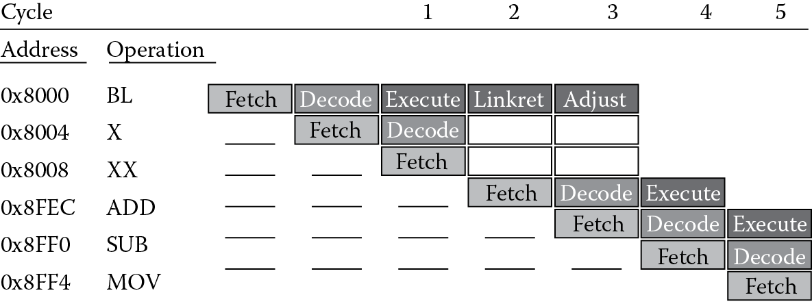
The branch instructions in the ARM instruction set, B and BL shown in Figure 8.2, have 24-bit fields for a branch offset. When the processor executes a branch instruction, this offset is added to the Program Counter, and the machine begins fetching instructions from this new address. Since a 32-bit instruction cannot hold a 32-bit address, a couple of questions immediately arise. First, if only 24 bits are available, what’s the best way to effectively use them? Rather than just adding this offset to register 15, the 24 bits are shifted left by two bits first, since all ARM instructions must be word-aligned anyway, i.e., the least significant two bits of the address are always zero. This gives a range of ±32 MB using this method and brings up the second question: how do you jump more than 32 MB away from the current address? Remember that register 15, the Program Counter, is just another register, so you can say something like
LDR pc, =0xBE000000
or
MOV pc, #0x04000000
which forces an address directly into the Program Counter.
For the most part, this chapter deals with one particular type of branch instruction—B—leaving the discussion of BL and BX for later chapters, but we’ll examine both conditional and unconditional branches. The unconditional instruction B alone simply forces the code to jump to some new address. However, it’s likely you’ll want to condition this decision with more criteria; for example, did a counter just expire or did an earlier subtraction result in a negative number? Table 8.1 shows various combinations of flags in ARM processors that can be used with branches. It is quite possible, then, to say
Condition Codes and Their Meaning
|
Field Mnemonic |
Condition Code Flags |
Meaning |
Code |
|
EQ |
Z set |
Equal |
0000 |
|
NE |
Z clear |
Not equal |
0001 |
|
CS/HS CC/LO MI |
C set C clear N set |
Unsigned ≥ Unsigned < Negative |
0010 0011 0100 |
|
PL |
N clear |
Positive or zero |
0101 |
|
VS |
V set |
Overflow |
0110 |
|
VC |
V clear |
No overflow |
0111 |
|
HI |
C set and Z clear |
Unsigned > |
1000 |
|
LS |
C clear and Z set |
Unsigned ≤ |
1001 |
|
GE |
N ≥ V |
Signed ≥ |
1010 |
|
LT |
N ≠ V |
Signed < |
1011 |
|
GT |
Z clear, N = V |
Signed > |
1100 |
|
LE |
Z set, N ≠ V |
Signed ≤ |
1101 |
|
AL |
Always |
Default |
1110 |
CMP r0, r1
BLT Sandwich ; programmers get hungry...
where this means if register r0 is less than register r1, branch to a label called Sandwich. Recall that the job of a comparison instruction is to set the flags in the CPSR and little else, so the branch instruction can immediately use that information to make decisions. We’ll certainly see more examples of conditional branches throughout the book, and shortly we’ll find that on the ARM7TDMI, almost any instruction can be conditionally executed.
Example 8.1
Suppose that you need to compare two signed numbers, where they are assumed to be in two’s complement form, with 0xFF000000 in register r0 and 0xFFFFFFFF in register r1. If you wanted to branch to some code only if the first number was less than the second, you might have something like
CMP r0, r1 ; r0 < r1?
BLT algor
For this case, the branch would be taken, as register r0 holds a large, negative number and register r1 holds –1. If you assume that the two numbers are unsigned, BCC should be used instead, as register r1 would hold the larger number.
Since any real code will have something more than just arithmetic and control instructions, the whole notion of looping through code needs to be addressed. We need the ability to execute a section of code multiple times, so we’re going to start off the discussion of loops by looking at a real problem. Suppose that we had a register containing a binary value that needed to be normalized. In other words, we need to have the leading 1 in the most significant bit, even if we have to shift it to get it there. This does actually come up in numerical algorithms, such as the Newton–Raphson division algorithm, logarithmic routines, and some priority decoders. This problem is so significant that ARM decided to add a new instruction (CLZ, or Count Leading Zeros) to the version 5TE architectures and beyond, just to reduce the cycle count of certain mathematical routines. Since the ARM7TDMI does not have this instruction, it makes a good example to code.
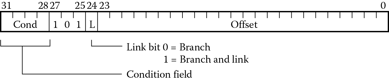
For our normalization task, the flowchart in Figure 8.3 might help to decide how this algorithm will be implemented. The first thing to test for is whether the argument is either zero or already normalized—if there’s nothing to do, then the routine should just stop. Otherwise, we want to shift it by one bit to the left and increment the shift counter, which could be used by another routine to tell how much the original value had to be shifted. The routine should check to see if the most significant bit is now set, as this would be the place to stop. If it’s not, the code should go back and repeat the shift/increment/test portion again.
The code for this algorithm might look like the following:
AREA Prog8a, CODE, READONLY
ENTRY
main
MOV r4, #0 ; clear shift count
CMP r3, #0 ; is the original value <= 0?
BLE finish ; if yes, we’re done
loop LSLS r3, r3, #1 ; shift one bit
ADD r4, r4, #1 ; increment shift counter
BPL loop
finish
B finish
END
The first type of branch we see is the BLE just above the loop statement. The comparison above sets the flags in the CPSR, and if the number is negative (indicated by the most significant bit being set) or zero, then the condition forces the code to branch to the label finish. Otherwise, it continues to the first instruction inside the loop, which shifts the value one place to the left. An important point to note here is that an “S” has been appended to the LSL instruction because we have to tell the machine to set the flags again for the loop condition. The ADD will not have any effect on the flags, since arithmetic instructions do not set flags unless told to do so. The BPL, or Branch if Positive or zero, instruction simply says to check the flags again, and as long as the most significant bit is clear, i.e., the value is still not normalized, to branch back to the label loop.
While this code would not occupy much memory, the issue that is probably not obvious is the cycle time that it would take to execute. Consider the worst case scenario where a 1 is in the least significant bit of the register, forcing 31 shifts to get it to the most significant bit. The LSL instruction takes one cycle to execute, as does the ADD. However, the branch instruction flushes the ARM7’s pipeline and causes a change of flow in the instruction stream, and the code repeats all of this 31 times. In total, this adds up to a significant number of cycles. Toward the end of the chapter, we will see two much more efficient ways to do this. For now, we’ll continue to examine ways to branch and how different types of loops are written.
8.2.2 Version 7-M Branches
Version 7-M cores have more branch instructions than the ARM7TDMI, but the types of allowable branches have some limitations:
- B—Branch. This is the simplest form of branch, where condition codes may be used to decide whether or not to branch to a new address in the code.
- BX—Branch indirect. A registered value is used as a branch target. If bit[0] of the address is a zero, a usage fault exception will occur. Use this instruction carefully, as the assembler will not be generating offsets or addresses for you, and the value in the register must have bit[0] set.
- BL—Branch with Link. As with the ARM7TDMI, the Link Register will hold a return address after a branch.
- BLX—Branch indirect with Link. This instruction is similar to BL, only the address is held in a register.
- CBZ, CBNZ—Compare and Branch if Zero, Compare and Branch if Nonzero. These two instructions are useful in looping and can reduce the number of instructions.
- IT blocks—IF-THEN blocks. The IT instruction can be used to avoid branching entirely with up to four instructions in a block.
The B, BX, and BL instructions work in the same way as in v4T architectures, namely to change the Program Counter to a new address from which the processor can begin fetching instructions. Both B and BL can be thought to contain immediate addresses, meaning that the address is encoded in the instruction itself. For example, you might say
B myroutine
and the linker will calculate the PC-relative offset necessary to jump to myroutine.
The BX and BLX instructions use an address contained in a register; for example,
BX r9
will load the value in register r9 into the Program Counter, and fetching begins from this new address.
Unlike v4T branch instructions, which always have a range of −32MB to 32MB, in version 7-M the range varies depending on which branch instruction you use. A 32-bit branch instruction has a range of −16MB to +16MB. A conditional branch used inside of an IT block (discussed shortly) has a range of −16MB to +16MB, while a conditional branch used outside of an IT block has a shorter range of −1MB to +1MB. In some cases, it might be necessary to force the longer instruction to be used to get the maximum range, for example
BEQ.W label
where the .W suffix denotes “wide”. For complete details, consult either (Yiu 2014) or the ARM v7-M Architectural Reference Manual (ARM 2010a).
With the introduction of Thumb-2 and Unified Assembly Language (UAL), it’s worth pointing out here that you’re likely to see some mixed use of the BX instruction. BX can be used to change the state of the machine from ARM to Thumb on the ARM7TDMI (covered in detail in Chapter 17), but it can also be used as a simple branch instruction, too, as long as the least significant bit is not set (this would throw us into Thumb state). This instruction takes a register value and loads it into the Program Counter. An example instruction might be
BX r4
where the value held in register r4 is moved to the PC and then execution begins from this new address. This leaves us with another way to return from subroutines, which are covered in Chapter 13. Rather than using the older instruction
MOV pc, lr
which transfers the contents of the Link Register into the Program Counter, you should now say
BX lr
which does the same thing. As you study code samples from other sources, you are likely to see both styles, so just keep this in mind as you read documentation and write your own code.
The Compare and Branch if Nonzero (CBNZ) and Compare and Branch if Zero (CBZ) instructions can be used to avoid changing the condition code flags during loops. As an example, if you assume that the CMP instruction does not change the flags, instead of saying
CMP r2, #0
BEQ label
you would use the single instruction
CBZ r2, label
as they are functionally equivalent statements. These two instructions come with a few restrictions worth noting. First, the only registers allowed must be in the range of r0–r7. Second, the branch destination must be within 4–130 bytes following the instruction. Finally, the CBZ and CBNZ instructions cannot be used within an IT block, which brings us to the subject of Section 8.3, looping.
8.3 Looping
Nearly all embedded code will have some form of loop construct, especially if an operating system is running or the application requires the processor to periodically check an input or peripheral. We’ll examine three easy loop structures—the while loop, the for loop, and the do-while loop, along with code samples that show their construction.
8.3.1 While Loops
Certainly, one of the more common constructs in C or C++, or any high-level language really, is the while loop, and its cousin, the for loop. Since the number of iterations of a while loop is not a constant, these structures tend to be somewhat simple. Suppose we had the following C code:
j = 100;
while (j! = 0) {
//do something
j— —;}
The while loop can be constructed on an ARM7TDMI as
MOV r3, #0x64
B Test
Loop .
. ; do something
.
SUB r3, r3, #1 ; j— —
Test .. ; evaluate condition j = 0?
BNE Loop
While loops evaluate the loop condition before the loop body. There is only one branch in the loop body itself. The first branch actually throws you into the first iteration of the loop.
The loop can be constructed for the Cortex-M4 using version 7-M instructions as
MOV r3, #0x64
Loop CBZ r3, Exit
; do something
SUB r3, #1 ; j— —
B Loop
Exit
Here the initial test is done at the start of the loop. The Compare and Branch if Zero (CBZ) instruction will test the counter against zero, and if it is equal to zero, branch outside the loop to Exit. Note that the CBZ instruction will only support forward branches, meaning only to addresses that add to the Program Counter, not those that subtract from it.
8.3.2 For Loops
The other common loop, the for loop, is actually just a variation of the while loop. Suppose you wish to create a for loop to implement a counter of some kind using a control expression to manage an index j, which is declared as an integer:
for (j = 0; j < 10; j + +) {instructions}
The first control expression (j = 0) just clears a variable and can execute before the loop begins. The second control expression (j < 10) is evaluated on each pass through the loop and determines whether or not to exit. The index increments at the end of each pass to prepare for a branch back to the start of the loop. In assembly, it might be tempting to code this loop as
MOV r1, #0 ; j = 0
LOOP CMP r1, #10 ; j < 10?
BGE DONE ; if j > =10, finish
.
. ; instructions
.
ADD r1, r1, #1 ; j + +
B LOOP
DONE ..
A much better way to do this is to count down rather than up. A for loop can be constructed using only one branch at the end, subtracting one from the counter register, and branching back to the top only when the counter value is not equal to zero, like this:
MOV r1, #10 ; j = 10
LOOP
.
. ; instructions
.
SUBS r1, r1, #1 ; j = j-1
BNE LOOP ; if j = 0, finish
DONE ..
This is actually more efficient in that a branch is removed and a comparison against zero comes for free, since we set the condition codes with the SUB instruction and use the B instruction to test whether or not the counter is now zero.
Example 8.2
Let’s translate the following C code to assembly using an ARM7TDMI-based microcontroller.
for (i = 0; i < 8; i + +) {
a[i] = b[7−i];
}
The index i is declared as an integer, and assume the arrays a and b contain only byte-wide data. We also need to have the array a be located in writable memory, so for this example, you will need to select a target device that contains some RAM. Since we’ll be using the LPC2132 microcontroller from NXP in Chapter 16, we can select this one as the target device now. It has 16 KB of on-chip RAM, and programming it now only requires that we know the starting address of RAM, which is 0x40000000. The code below implements the above for loop.
AREA Prog8b, CODE, READONLY
SRAM_BASE EQU 0x40000000
ENTRY
MOV r0, #7 ; i
ADR r1, arrayb ; load address of array
MOV r2, #SRAM_BASE ; a[i] starts here
Loop
RSB r3, r0, #7 ; index = 7−i
LDRB r5, [r1, r3] ; load b[7−i]
STRB r5, [r2, r0] ; store into a[i]
SUBS r0, r0, #1 ; i— —
BGE Loop
done B done
ALIGN
arrayb DCB 0xA,0x9,0x8,0x7,0x6,0x5,0x4,0x3
END
The code starts by setting the index i to 7. The address of array b, which is located in memory just after our program code, is loaded into register r1. The address of array a, which will be located in SRAM on the chip, is placed in register r2. The reverse subtract operation calculates the difference between 7 and i to use as a pointer into memory. The data is loaded from memory into register r5 with a load byte instruction (LDRB), and then stored into array a using a store byte instruction (STRB). The counter is decremented, setting the flags for our upcoming comparison. The BGE (Branch if Greater than or Equal to zero) examines the flags, and based on the state of the N and the V flags, branches to the start of the loop. Notice that the data for array b is placed in the code using a DCB statement, which simply places byte-wide (8-bit) constants in the instruction memory. The other important thing to note here is that our loop is created with just one branch statement, since the comparison is built into the branch instruction.
Example 8.3
In this next example for the ARM7TDMI, suppose we have six 32-bit integers that need to be summed together, where the integer data is stored in memory. This might be equivalent to a C statement such as
sum = 0;
for (i = 0; i < 6; i + +) {
sum += a[i];
}
While simple loops don’t often require a flowchart, we might sketch one out to help define the steps necessary to write the assembly, as shown in Figure 8.4.
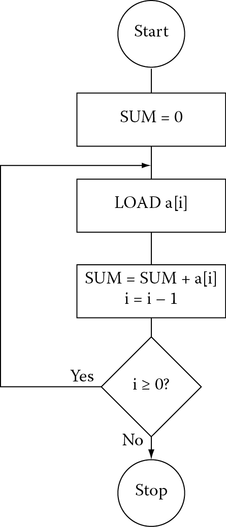
The code can be written in just a few lines, with one branch and no CMP instructions by simply counting down:
AREA Prog8c, CODE, READONLY
ENTRY
MOV r0, #0 ; sum = 0
MOV r1, #5 ; # of elements -1
ADR r2, arraya ; load start of array
Loop
LDR r3,[r2,r1,LSL #2] ; load value from memory
ADD r0, r3, r0 ; sum += a[i]
SUBS r1, r1, #1 ; i = i−1
BGE Loop ; loop only if i > =0
done B done
ALIGN
arraya DCD -1,-2,-3,-4,-5,-6
END
The code begins by clearing out the accumulated sum held in register r0. While there are six elements to add, we only load the value 5 into an index register because the values will be loaded from memory using an address with an offset, and therefore, we can use the fact that one of the elements is addressed with an offset of zero. The start of the array in memory is loaded into register r2 using the pseudo-instruction ADR. Notice that the data is declared at the end of the code with a DCD directive and ends up being located just at the end of our code in instruction memory. However, this data could just as easily have been located somewhere else in memory, such as in a peripheral, in SRAM, or elsewhere on the microcontroller.
At the beginning of the loop, register r3 is loaded with one word of data, and the value is then added into the accumulated sum. The counter for the loop is decremented with the SUBS instruction that sets the flags. Recall that we can use the condition codes for a variety of branch types, as well as conditional execution, which we’ll see in the next section. The BGE instruction causes the processor to branch back to our label Loop only if the subtraction produced a value that was greater than or equal to zero. Once the counter becomes negative, the loop terminates.
8.3.3 Do-While Loops
Here the loop body is executed before the condition is evaluated. The structure is the same as the while loop but without the initial branch:
LOOP
...
; loop body
...
; evaluate condition
BNE LOOP
EXIT
...
8.4 Conditional Execution
As we saw in the beginning of the chapter, branches can potentially cause very large delays in code, so if there were a way to remove a branch entirely, not only would our execution time decrease but our code size would decrease, too. Conditional execution provides this ability, since we can precondition an instruction as it goes through the pipeline—if it’s not even necessary to execute the instruction, it passes through without affecting anything. It still takes a clock cycle, and still holds a place in the pipeline, but nothing happens.
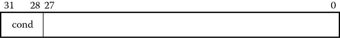
8.4.1 v4T Conditional Execution
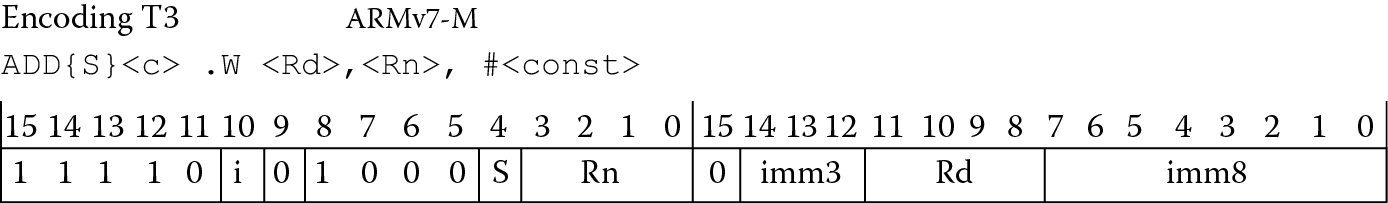
All version 4T ARM instructions can be conditionally executed based on the four-bit field in the upper nibble of the instruction, shown in Figure 8.5. Fortunately, you can still specify these conditions using the same mnemonics that we use for branches from Table 8.1. Careful readers will have noticed that there are 15 different field mnemonics, such as GT, GE, LT, etc., but there are actually 16 combinations—this is a four-bit field. Figure 8.6 shows an arbitrary Thumb-2 instruction, a 32-bit wide ADD instruction, which allows more flexibility than the 16-bit ADD instruction. Notice that bits 28 through 31, the upper nibble of the instruction, are all ones. In earlier ARM architectures, this encoding was used for the condition Never (NV), which seems a little unusual given that one normally hopes to have instructions used at least once in compiled code! By using this encoding to identify some of the new, 32-bit Thumb-2 instructions, the instruction space was given a bit of breathing room, allowing for more operations to be added.
It’s at this point that we can also begin to see why Thumb-2 instructions could not be conditionally executed like those in the v4T ISA, primarily for two reasons: 16-bit Thumb instructions have no extra bits for a conditional field, and if another construct is used, something beyond the traditional Thumb instructions will be needed. By adding a new instruction called IT to build small IF-THEN loops, this limitation can be overcome, as we’ll see shortly. For now, let’s examine how ARM instructions can be conditionally executed using the conditional field.
Example 8.4
Suppose you had to test a string for the presence of either a “!” or a “?” character, and you had one-byte character data called char. The test condition might be written in C as
if (char = = ‘!’ || char = =’?’)
found + +;
Assuming that the character data char was held in register r0 and the variable found was in register r1, you could write the assembly for this as
TEQ r0,#’!’
TEQNE r0,#’?’
ADDEQ r1,r1,#1
Recall that the TEQ instruction tests equivalence of two things by using the exclusive OR operation, always setting the flags in the CPSR afterward. If the two numbers were in fact the same, the Z flag would be set, so the second TEQ instruction would not be executed. The third instruction would be executed, since the Z flag has not been changed since the first comparison and the condition is still true.
Example 8.5
At the risk of being almost overused as an example, the greatest common divisor algorithm is still worth presenting here, as it demonstrates the power of conditional execution. Euclid’s algorithm for computing the GCD of two positive integers (a,b) can be written as
while (a != b) {
if (a > b) a = a – b;
else b = b – a;
}
To illustrate how this works, if you had the numbers 18 and 6, you would always subtract the smaller number from the larger until the two are equal. This gives 12 and 6 on the first pass, and 6 and 6 on the second and final pass.
Assuming that the numbers a and b are held in registers r0 and r1, respectively, the assembly code might look something like this if only the branches are executed conditionally:
gcd CMP r0,r1 ; a > b?
BEQ end ; if a = b we’re done
BLT less ; a < b branches
SUB r0,r0,r1 ; a = a-b
B gcd ; loop again
less SUB r1,r1,r0 ; b = b-a
B gcd
The most efficient way to do this is to avoid the branches altogether and conditionally execute the instructions, as
gcd CMP r0, r1
SUBGT r0, r0, r1
SUBLT r1, r1, r0
BNE gcd
Not only does this code execute more quickly, it contains fewer instructions. Note that in the second case, the code compares the two numbers, setting the flags. The two subsequent instructions are mutually exclusive, so there will never be a case where one of the numbers is less than and greater than the other at the same time. The final case where the two numbers are equal after the compare forces both subtraction instructions to be ignored in the pipeline, and the final branch instruction falls through as well because they are, in fact, equal. Not having the extra branches in the code makes a huge difference, since the pipeline does not get flushed repeatedly when the branches are taken.
8.4.2 v7-M Conditional Execution: The IT Block
It was stated in the last section that a new instruction was combined with the older Thumb instruction set to allow small IF-THEN blocks to be built. Like conditional execution, the goal is to remove or avoid branches as much as possible in Thumb-2 code. The IT instruction is used in conjunction with other operations to build blocks using the following syntax:
ITxyz condition
where the x, y, and z fields specify either T for THEN (true) or E for ELSE (false). For example, a simple IF-THEN statement such as
if (r3 < r8){
r3 = r3 + r8;
r4 = 0;}
else
r3 = 0;
might be coded as
ITTE LT
ADDLT r3, r3, r8
MOVLT r4, #0
SUBGE r3, r3, r3
Here the ADD and MOV instructions have the same condition specified in the ITTE instruction (LT), and the ELSE instruction reflects the inverse condition (GE). There are up to four instructions in an IF-THEN block and a few simple rules that govern its construction:
- The condition field must be one of the fields listed in Table 8.1, except Always.
- The first statement following the IT instruction must be the true-then-execute case (THEN).
- The number of T’s and E’s in the IT instruction itself should match the number of THEN and ELSE instructions in the block. If you specify an instruction such as ITTEE, there should be two THEN instructions and two ELSE instructions following the IT instruction.
- Branches to any instruction in the IT block are not permitted, apart from those performed by exception returns.
- Any branches used in an IT block must be the last instruction in the block.
- The ELSE condition must be the inverse of the THEN condition. If you refer to Table 8.1 again, you will notice that these two fields differ only in the LSB of the encoding. In other words, GE, which is 1010, is the inverse of LT, which is 1011.
Note that the IT instruction does not affect the condition code flags. If you use 16-bit instructions in the IT block, other than CMP, CMN, and TST, they do not set the condition code flags either.
Example 8.6
In Chapter 16, we will examine a program that changes the color of the LEDs on a Tiva Launchpad. One small section of the code can be stated in C as
if (Color = = 8)
Color = 2;
else
Color = Color * 2;
This forces the Color variable to take on the values 2, 4, or 8, and then to cycle through those same values over and over. Assuming our variable is held in register r6, the assembly for the Cortex-M4 would look like
CMP r6, #8
ITE LT
LSLLT r6, r6, #1 ; LED = LED * 2
MOVGE r6, #2 ; reset to 2 otherwise
The first comparison tests against our upper limit (8) and sets the flags for our conditional instructions coming up. Notice that the IT instruction specifies only one Less Than instruction (LSL) and one Else instruction (MOV). The IT block then begins with a logical shift of the value in register r6 if the value was either two or four. Otherwise, the value is reset to the starting value of two with a simple MOV. The Else instruction is predicated with the inverse condition of LT.
8.5 Straight-Line Coding
Now that we’ve seen how branches are done, you might ask if an algorithm that contains a loop necessarily has to have a branch instruction. The answer is no. It turns out that in many algorithms, especially signal processing algorithms, speed is the most important consideration in its implementation. If any delays can be removed from the code, even at the expense of memory, then sometimes they are. Instructions that are between the start of a loop and the branch back to the beginning can be repeated many times, a process known as unrolling a loop. For example, if you had one instruction that was inside of a for loop, i.e.,
MOV r1, #10 ; j = 10
Loop
MLA r3, r2, r4, r5 ; r3 = r2*r4 + r5
SUBS r1, r1, #1 ; j = j – 1
BNE Loop ; if j = 0, finish
you could do away with the for loop entirely by simply repeating the MLA instruction 10 times.
If you recall from the normalization example presented at the beginning of the chapter, a branch forces a pipeline to flush instructions that have already been fetched and decoded; therefore, a routine may spend considerable time just refilling the pipeline. To avoid this, software can simply remove all branches—the routine may be significantly faster but it will occupy more memory because of the repeated instructions. The normalization routine in Section 8.2.1 has been optimized by Symes (Sloss, Symes, and Wright 2004) and is presented below. Notice that the cycle count is fixed for this routine—17 cycles for an ARM7TDMI—due to the conditional execution and lack of branches. The instructions that are not executed, those that fail their condition codes, still have to go through the pipeline and still take a cycle in the execute stage.
; Normalization on the ARM7TDMI
; Argument in r0
; Shift count needed for normalization returned in r1
shift RN r0
x RN r1
AREA Prog8d, CODE, READONLY
ENTRY
MOV shift, #0 ; shift = 0
CMP x, #1<<16 ; if (x < (1<<16))
LSLCC x, x, #16 ; {x = x<<16;
ADDCC shift, shift, #16 ; shift + =16;}
TST x, #0xFF000000 ; if (x < (1<<24))
LSLEQ x, x, #8 ; {x = x <<8;
ADDEQ shift, shift, #8 ; shift + =8;}
TST x, #0xF0000000 ; if (x < (1<<28))
LSLEQ x, x, #4 ; {x = x<<4;
ADDEQ shift, shift, #4 ; shift + =4;}
TST x, #0xC0000000 ; if (x < (1<<30))
LSLEQ x, x, #2 ; {x = x<<2;
ADDEQ shift, shift, #2 ; shift + =2;}
TST x, #0x80000000 ; if (x < (1<<31))
ADDEQ shift, shift, #1 ; {shift + =1 ;
LSLEQS x, x, #1 ; x << = 1;
MOVEQ shift, #32 ; if (x = =0) shift = 32;}
done B done
END
As a point of interest, it was mentioned earlier that a new instruction, Count Leading Zeros (CLZ), was added to the v5TE instruction set, and it is included in the v7-M instructions. The entire routine above can be done in two lines of code on the Cortex-M4:
; r2 = shift count
; r3 = original value
CLZ r2, r3
LSL.W r3, r3, r2 ; r3 << shift count
8.6 Exercises
- Code the following IF-THEN statement using Thumb-2 instructions:
if (r2 != r7)
r2 = r2 − r7;else
r2 = r2 + r4;
- Write a routine for the ARM7TDMI that reverses the bits in a register, so that a register containing d31d30d29…d1d0 now contains d0d1…d29d30d31. Compare this to the instruction RBIT on the Cortex-M4.
- Code the GCD algorithm given in Section 8.4.1 using Thumb-2 instructions.
- Find the maximum value in a list of 32-bit values located in memory. Assume the values are in two’s complement representations. Your program should have 50 values in the list.
- Write a parity checker routine that examines a byte in memory for correct parity. For even parity, the number of ones in a byte should be an even num-ber. For odd parity, the number of ones should be an odd number. Create two small blocks of data, one assumed to have even parity and the other assumed to have odd parity. Introduce errors in both sets of data, writing the value 0xDEADDEAD into register r0 when an error occurs.
- Compare the code sizes (in bytes) for the GCD routines in Section 8.4.1, where one is written using conditional execution and one is written using branches.
- Digital signal processors make frequent use of Finite Impulse Response filters. The output of the filter, y(n), can be described as a weighted sum of past and present input samples, or
- where the coefficients h(m) are calculated knowing something about the type of filter you want. A linear phase FIR filter has the property that its coefficients are symmetrical. Suppose that N is 7, and the values for h(m) are given as
h(0) = h(6) = −0.032
h(1) = h(5) = 0.038
h(2) = h(4) = 0.048
h(3) = −0.048
- Use the sample data x(n) below:
SAMPLE DCW 0x0034,0x0024,0x0012,0x0010
DCW 0x0120,0x0142,0x0030,0x0294
- Write an assembly language program to compute just one output value, y(8), placing the result in register r1. You can assume that x(8) starts at the lowest address in memory and that x(7), x(6), etc., follow as memory addresses increase. The coefficients should be converted to Q15 notation, and the input and output values are in Q0 notation.
- Write a routine to reverse the word order in a block of memory. The block contains 32 words of data.
- Translate the following conditions into a single ARM instruction:
- Add registers r3 and r6 only if N is clear. Store the result in register r7.
- Multiply registers r7 and r12, putting the results in register r3 only if C is set and Z is clear.
- Compare registers r6 and r8 only if Z is clear.
- The following is a simple C function that returns 0 if (x + y) < 0 and returns 1 otherwise:
int foo(int x, int y){if (x + y < 0)
return 0;
else
return 1;
}
- Suppose that a compiler translated it into the following assembly:
foo ADDS r0, r0, r1
BPL PosOrZ
done
MOV r0, #0
BX lr
PosOrZ
MOV r0, r1
B done
- This is inefficient. Rewrite the assembly code for the ARM7TDMI using only four instructions (hint: use conditional execution).
- Write Example 7.10 (finding the absolute value of a number) for the Cortex-M4.
- What instructions are actually assembled if you type the following lines of code for the Cortex-M4 into the Keil assembler, and why?
CMP r3, #0
ADDEQ r2, r2, r1