Table of Contents for
ARM Assembly Language, 2nd Edition
 ARM Assembly Language, 2nd Edition
Published by
Chapman and Hall/CRC, 2016
ARM Assembly Language, 2nd Edition
Published by
Chapman and Hall/CRC, 2016
- Contents
- ARM Assembly Language: Fundamentals and Techniques, Second Edition
- Preliminaries
- To our families
- Preface
- Acknowledgments
- Authors
- Chapter 1 - An Overview of Computing Systems
- Chapter 2 - The Programmer’s Model
- Chapter 3 - Introduction to Instruction Sets: v4T and v7-M
- Chapter 4 - Assembler Rules and Directives
- Chapter 5 - Loads, Stores, and Addressing
- Chapter 6 - Constants and Literal Pools
- Chapter 7 - Integer Logic and Arithmetic
- Chapter 8 - Branches and Loops
- Chapter 9 - Introduction to Floating-Point: Basics, Data Types, and Data Transfer
- Chapter 10 - Introduction to Floating-Point: Rounding and Exceptions
- Chapter 11 - Floating-Point Data-Processing Instructions
- Chapter 12 - Tables
- Chapter 13 - Subroutines and Stacks
- Chapter 14 - Exception Handling: ARM7TDMI
- Chapter 15 - Exception Handling: v7-M
- Chapter 16 - Memory-Mapped Peripherals
- Chapter 17 - ARM, Thumb and Thumb-2 Instructions
- Chapter 18 - Mixing C and Assembly
- Appendix A: Running Code Composer Studio
- Appendix B: Running Keil Tools
- Appendix C: ASCII Character Codes
- Appendix D
- Glossary
- References
Chapter 10
Introduction to Floating-Point
Rounding and Exceptions
10.1 Introduction
Rounding is one of the most important but confusing aspects of floating-point. We learned this early in school with problems asking for the nearest whole number when we divided 9 by 4. The pencil and paper result is 2.25, but what whole number do we give in the answer? The solution, we were taught, is to add 0.5 to the result and drop the fraction. So,
9/4 + 0.5 = 2.75,
and dropping the fraction gives 2. What if the problem was 9 divided by 2? We get 4.5, and adding 0.5 gives us 5. Is this the best we can do, since the computed value is exactly halfway between two whole numbers? We have the same issue in floating-point. The result of each operation must be a representable value, but what if the intermediate result of the operation was not? We have to round the intermediate result to a representable value. In this chapter we will look carefully at rounding and the various rounding modes specified by the IEEE 754-2008 specification.
A second important issue concerns what we do when an operation has no mathematically agreed upon answer, such as 0/0, or if some unusual event occurred in our computation. We call these situations exceptions, and while they are often not problematic, sometimes it can signal a situation that may require attention. We will consider each of these exceptions first generally, and then the specific response of the Cortex-M4 with floating-point hardware to the situations that signal each exception. Next we will consider whether we can count on some of the mathematical laws we learned in school, and finish the chapter looking at normalization and cancelation, two steps in floating-point computation and how they impact rounding and exceptions.
10.2 Rounding
Since only a finite set of representable values exists for each floating-point data type, we must have a method to deal with a computation that does not result in a representable value. For example, when we add
1.0 (0x3F800000) + 224 (0x4B800000)
on a Cortex-M4, with the default rounding mode (roundTiesToEven), the answer is
224 (0x4B800000).
Why is the result the same as the second operand? Where is the contribution of the first operand? When we add a 1 to an integer, we expect the result to be the input integer incremented by one. On first glance, this seems to be an error. However, in this floating-point example, it makes no difference to the final result that we added 1.0 to 224. In fact, it makes no difference whether we add 1.0 to 224 once, or whether we add it a million times. Each time this instruction is executed we will get the same result. How can this be? The answer is one of the most important features, and programming landmines, in using floating-point arithmetic, namely the frequent need to round the computed result to a representable value. The IEEE 754-2008 standard requires that each computation be computed as if to infinite precision* and then rounded to a representable value or a special value. Internal to the Cortex-M4, the computation is performed to an intermediate precision larger than single-precision, which represents the infinitely precise internal sum, of
1.0 + 224 = 16,777,217.0
as we would expect. However, this value is not a representable value for the single-precision data type. Recalling the formula for single-precision values
F = (−1)s × 2(exp−bias) × 1.f (9.1)
which we saw earlier in Sections 1.5.2 and 9.4, the value 224 + 1.0, results in the following floating-point component parts according to our formula (the significand part is represented in binary and the exponent in decimal):
16,777,217.0 = (−1)0 × 2(151−127) × 1.000000000000000000000001
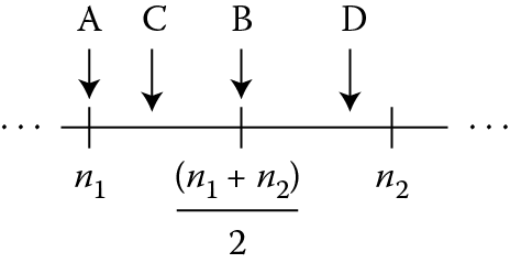
Recall a single-precision value has only 23 fraction bits (bits [22:0] in a representation with the least-significant bit numbered 0). There are 24 bits in the significand of our example after the binary point, and only 23 of them can fit in the final significand. So we must select a representable value to return in place of the infinitely precise internal value. Every computation results in either exactly a representable value or one between two representable values, as shown in Figure 10.1. In this figure, values n1 and n2 are representable values in single-precision. Result A is exactly the representable value n1; result B is exactly halfway between representable values n1 and n2; result C is closer to representable value n1, while result D is closer to representable value n2. In each case, the representable value to be returned is determined by the current rounding mode and the bits in the infinitely precise internal value.
Each of the available rounding modes is the subject of the following sections, which describe the rounding modes defined in the IEEE 754-2008 standard, and those that are available in the Cortex-M4.
10.2.1 Introduction to Rounding Modes in the IEEE 754-2008 Specification
The IEEE 754-2008 standard specifies that the computed infinitely precise internal value be rounded to a representable value according to a selected rounding mode. Five rounding modes are specified by the standard:
roundTiesToEven
roundTiesToAway
roundTowardPositive
roundTowardNegative
roundTowardZero
We will focus our attention on four of these: roundTiesToEven, which we sometimes refer to as Round to Nearest Even, or RNE†; roundTowardPositive, also known as Round to Plus Infinity, or RP; roundTowardNegative, also known as Round to Minus Infinity, or RM; and roundTowardZero, also known as Round to Zero, or RZ.‡ Recall from Chapter 9, the rounding mode is set in the FPSCR in the Cortex M4, and the VMSR and VMRS instructions, covered in Chapter 11, enable the reading and writing of the FPSCR.
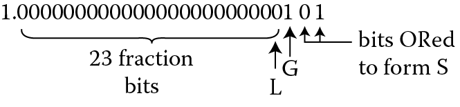
Inside the processor, a computed result will have additional bits beyond the 23 bits of the fraction. These bits are computed faithfully, that is, they are correct for the operation; however, they are not simply more bits of precision. Rather, two additional bits are computed—the guard bit and the sticky bit, shown in Figure 10.2. The guard bit is the bit immediately lower in rank than the least-significant bit position in the final result. If the infinitely precise internal significand were normalized to the range [1.0, 2.0), this would be the 25th bit of the significand, counting from left to right. The sticky bit is formed by ORing all bits with lower significance than the guard bit. In other words, if the final result was computed to 40 bits, the upper 24 bits would be the significand of the pre-rounded, final result; the next bit would be the guard bit; and the OR of the final 15 bits would be the sticky bit.
Example 10.1
Add 224 (0x4B800000) + 1.25 (0x3FA00000)
Solution
The value 224 is much larger than 1.25, and when represented in single-precision format, the 1.25 only contributes in the guard and sticky bits. When represented in infinite precision, we can see all the bits in the intermediate sum.
1.25 + 224 = (−1)0 × 2(151−127) × 1.00000000000000000000000101
The guard bit is the 1 in bit position 2 (counting from the right side), while the sticky bit would be the OR of bits 0 (bit position 1) and 1 (bit position 0) and would be 1. We also refer to the least-significant bit of the pre-rounded significand as the L bit (for least-significant bit, or LSB). See Table 10.1.
Significand with Guard and Sticky Bits
|
Value |
20 |
2− 1 …2− 22 |
2− 23 (“L”) |
Guard (“G”) |
Bits Contributing to the Sticky Bit (“S”) |
|
|
Bit position |
25 |
24…4 |
3 |
2 |
1 |
0 |
|
Bit value |
1. |
0…0 |
0 |
1 |
0 |
1 |
10.2.2 The roundTiesToEven (RNE) Rounding Mode
The roundTiesToEven (RNE) rounding mode is the default rounding mode in the Cortex M4. The following equation governs the decision to increment the significand:
Increment = (L & G)|(G & S)
In truth table form this equation looks like Table 10.2.
roundTiesToEven Rounding Summary
|
L LSB |
G Guard |
S Sticky |
Increment? |
Note |
|
0 |
0 |
0 |
No |
Pre-rounded result is exact, no rounding necessary |
|
0 |
0 |
1 |
No |
Only sticky set |
|
0 |
1 |
0 |
No |
Tie case, L bit not set |
|
0 |
1 |
1 |
Yes |
Guard and Sticky set—rounding bits >1/2 LSB |
|
1 |
0 |
0 |
No |
Pre-rounded result is exact, no rounding necessary |
|
1 |
0 |
1 |
No |
Only L bit and Sticky set |
|
1 |
1 |
0 |
Yes |
Tie case, L-bit set |
|
1 |
1 |
1 |
Yes |
Guard and sticky set—rounding bits are >1/2 LSB |
The roundTiesToEven rounding mode causes the significand to be incremented whenever the bits not part of the pre-rounded significand would contribute greater than 1/2 the LSB value to the final result, and never when the bits would contribute less than 1/2 the LSB value. In the case of the bits contributing exactly 1/2 of the LSB, the pre-rounded significand is incremented when it is odd, that is, the L bit is set, and not when it is even. This is what the Even signifies in the name roundTiesToEven. This paradigm for rounding results is the statistically most accurate results for a random sample of operations and operands.
So let’s return to our example case of adding 1.25 to 224. We know that the significand of the final value is 1.00000000000000000000000101. In Figure 10.2 we identified the L, G, and S bits.
The guard bit adds exactly 1/2 the value of the L bit to the significand, and the sticky bit increases the rounding contribution to greater than 1/2 of the L bit value. The significand does get incremented, and we have 224 + 2 as a final result.
Example 10.2
Show a pair of operands that, when added, demonstrate the tie case without an increment.
Solution
The two operands could be 16,777,216 (224) and 1.0.
From Figure 10.2, the contribution of the 1.0 term would be only the G bit. L and S are each zero. From Table 10.2, we would not increment in this case (see the third line from the top of the table.)
Example 10.3
Show a pair of operands that, when added, demonstrate the tie case with an increment.
Solution
The two operands could be 16,777,218 (224 + 2.0) and 1.0.
From Figure 10.2, the contribution of the 1.0 term would be only the G bit. L is set to a one and S is zero. From Table 10.2, we would increment in this case (see the seventh line from the top of the table.)
Example 10.4
Show a pair of operands that, when added, demonstrate an increment due to G and S.
Solution
The two operands could be 16,777,216 (224) and 1.25.
From Figure 10.2, the contribution of the 1.25 term would be the G and S bits each set. L is zero. From Table 10.2, we would increment in this case. (See the fourth line from the top of the table.)
10.2.3 The Directed Rounding Modes
The other three rounding modes are called directed rounding modes. These find use in specialized mathematical operations in which creating a bound of a problem is more useful than computing a single result. In these instances, knowing the bounds of a function with a specific data set conveys more useful information about the error range than would a single result of unknown accuracy. One such area of mathematics is called interval arithmetic. In interval arithmetic, each value is represented as a pair of bounds, representing the range of possible numerical values for a result rather than a single result value. These computations are useful when the true value cannot be known due to measurement inaccuracies, rounding, or limited precision.
For example, we may say a friend’s height is between 6 feet and 6 feet two inches. While we don’t know exactly the height of our friend, we are sure he is at least 6 feet but no more than 6 feet 2 inches tall. If we were to measure the average height of a class of boys, we could measure each boy using a tape measure, but each of these measurements may not be accurate. For example, we measure Tom to be 6 foot 3/4 inches. But is this his true height? Perhaps he has let his hair grow and this added a 1/4 inch, or his shoes or socks are contributing to our measurement. Next week he will get his hair cut, and he would measure only 6 foot 1/2 inches. If we record the boys’ heights to a precision of 1 inch, rounding any fraction down for a lower value and rounding up for a higher value, we could create a pair of bounding values, each with a precision of 1 inch, one lower than the measured value, and one higher than the measured value. With the measurement we have for Tom, we could record Tom’s height as (6′ 0″, 6′ 1″). This way we give accurate bounds for his height, but not a specific number. In floating-point interval arithmetic, we would round any imprecise value, both down, for a lower bound, and up, for a higher bound, creating a bounding pair for all computations. When we have all the measurement pairs for the class, we would compute an average of the lower entries in each pair, and an average of the upper entries in the pairs, producing again another pair. Now we can say with some certainty that the average height of the boys in the class is between the lower bound and the upper bound. As you can see, while this is imprecise, in that we don’t have a single value, it is more accurate than any single number could be.
The three directed rounding modes are often used in interval arithmetic, and are discussed below.
10.2.3.1 The roundTowardPositive (RP) Rounding Mode
This rounding mode will increment any imprecise positive result, and not increment any precise or negative result. The inputs to the rounding equation are G and S bits, the sign bit, and incrementing is done if both the pre-rounded result is positive and if either G or S is set. If the pre-rounded result is negative, no incrementing is done. In this mode, the increment equation is
Increment = ~sign & (G|S)
Recall the sign bit in a positive floating-point number is 0. If we consider Example 10.4, we see the S bit is set and the sign is positive (sign = 0). In RP mode the final significand would be incremented.
10.2.3.2 The roundTowardNegative (RM) Rounding Mode
Some explanation is useful here. When we say a value in incremented, we are referring to the significand regardless of the sign off the value. For example, if we have in −1.75 in decimal and we round this value up, we would have −2.0. Simply put, an increment always causes the result to be further from zero, regardless of the sign of the result.
The RM rounding mode will increment any imprecise negative result, and not increment any precise or positive result. This mode is the negative sign bit counterpart to the roundTowardPositive rounding mode. If the pre-rounded result is negative, and if either G or S is set, the mantissa is incremented. If the pre-rounded result is positive, no incrementing is done. In this mode the increment equation is
Increment = sign & (G|S)
If we consider again Example 10.4, the S bit set and the sign positive (sign = 0) would dictate that the final significand would not be incremented. If the sign of the result were negative in the example, the roundTowardNegative rounding mode would dictate incrementing the final significand.
10.2.3.3 The roundTowardZero (RZ) Rounding Mode
The roundTowardZero (RZ) mode is also called truncate, and this rounding mode never increments an intermediate value, but simply drops any guard and sticky bits. Any bits computed beyond the L bit are ignored. This the mode commonly used in integer arithmetic in processors with divide operations. In this mode the increment equation is
Increment = 0
In other words, we never increment the result in the roundTowardZero rounding mode. In Example 10.4, even though the G and S bits are set, the final significand is not incremented. All the bits to the right of the L bit are simply truncated.
10.2.4 Rounding Mode Summary
The operation of these four rounding modes may be summarized by the diagram in Figure 10.3. The values n and n + 1 ulp§ are two, contiguous, representable floating-point values. The value n + 1/2 ulp represents the point halfway between the two representable floating-point values but is not itself a representable floating-point value.
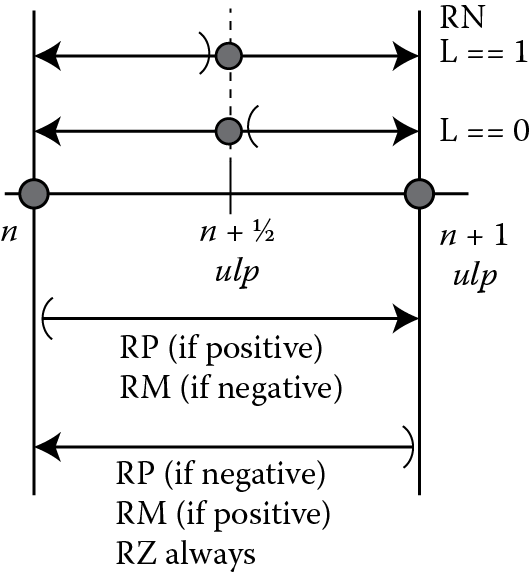
Consider first the upper two lines in Figure 10.3. These lines represent the behavior of the RNE rounding mode, and the handling of tie cases depends on the value of L, the least significant bit of the internal normalized significand (more on normalization in Section 10.5). In the top line, L is 1, indicating the normalized significand is odd. In this case the tie case rounds up to make the result significand even. In the second line the internal normalized significand is even before the rounding decision, and a tie case will not increment, leaving the result even. In both cases, if the infinitely precise internal value is greater than n + 1/2 ulp, the internal value is incremented, and if less, the internal value is not incremented. The third line indicates the behavior of RP for a positive result and RM for a negative result, while the last line indicates the behavior of RP for a negative result, RM for a positive result, and RZ always. In both RP and RM, the decision to increment is made on the sign of the result, the rounding mode, and whether the internal normalized significand is exactly a representable value. To complete Table 10.1, we add in the three directed rounding modes to form Table 10.3.
Rounding Mode Summary
|
Sign |
Rounding Bits |
Increment? Rounding Mode |
Data Characteristic |
|||||
|
L |
G |
S |
RNE |
RP |
RM |
RZ |
||
|
0 |
0 |
0 |
0 |
No |
No |
No |
No |
Exact |
|
1 |
0 |
0 |
0 |
No |
No |
No |
No |
Exact |
|
0 |
0 |
0 |
1 |
No |
Yes |
No |
No |
Inexact—positive |
|
1 |
0 |
0 |
1 |
No |
No |
Yes |
No |
Inexact—negative |
|
0 |
0 |
1 |
0 |
No |
Yes |
No |
No |
Inexact—positive, tie case |
|
1 |
0 |
1 |
0 |
No |
No |
Yes |
No |
Inexact—negative, tie case |
|
0 |
0 |
1 |
1 |
Yes |
Yes |
No |
No |
Inexact—positive |
|
1 |
0 |
1 |
1 |
Yes |
No |
Yes |
No |
Inexact—negative |
|
0 |
1 |
0 |
0 |
No |
No |
No |
No |
Exact |
|
1 |
1 |
0 |
0 |
No |
No |
No |
No |
Exact |
|
0 |
1 |
0 |
1 |
No |
Yes |
No |
No |
Inexact—positive |
|
1 |
1 |
0 |
1 |
No |
No |
Yes |
No |
Inexact—negative |
|
0 |
1 |
1 |
0 |
Yes |
Yes |
No |
No |
Inexact—positive, tie case |
|
1 |
1 |
1 |
0 |
Yes |
No |
Yes |
No |
Inexact—negative, tie case |
|
0 |
1 |
1 |
1 |
Yes |
Yes |
No |
No |
Inexact—positive |
|
1 |
1 |
1 |
1 |
Yes |
No |
Yes |
No |
Inexact—negative |
Let’s consider a multiplication example to demonstrate the four rounding modes.
Example 10.5
Multiply 0x3F800001 (1.00000011920928955) by 0xC4D00000 (−1664) in each rounding mode and compute the result.
Solution
Let OpA = 0x3F800001 and OpB = 0xC4D00000. The two operands are shown in their component parts in Table 10.4.
Operands for Example 10.5
|
OpA: |
0x3F800001 |
= |
− 1 0 |
x |
2 0 |
x |
1.00000000000000000000001 |
|
OpB: |
0xC4D00000 |
= |
− 1 1 |
x |
2 10 |
x |
1.10100000000000000000000 |
Recall that in integer multiplication, we take each digit of the multiplier, and if it is a 1 we include the multiplicand shifted to align bit [0] of the multiplicand with the multiplier bit. If the bit is a zero, we skip it and go on to the next bit. In the diagram below, there are two multiplier bits, OpA[0] and OpA[23], resulting in two partial product terms, called OpA[0] term and OpA[23] term. These two partial products are summed using binary addition to form the infinitely precise product. Since the two significands are 24 bits each, the product will be (24 + 24 −1), or 47 bits. If the summing operation produced a carry, the product would have 48 bits; however, in this case there is no carry, so only 47 bits are valid. The L bit and G bit, and the bits which will be ORed to make the S bit (identified with a lowercase s) are marked in the line pre-rounded product. In this example, L is 1, so our pre-rounded product is odd; G is 1, and S is 1. From Table 10.5, for the RNE and RM rounding modes the pre-rounded product will be incremented to form the result product, but for the RP and RZ rounding modes the pre-rounded product is not incremented. (Notice the product is negative.)
Example 10.5 Intermediate Values
|
Operand Significand |
|||||
|
OpB Significand (Multiplicand) |
1 |
101 |
00000000000000000000 |
||
|
OpA Significand (Multiplier) |
1 |
000 |
00000000000000000001 |
||
|
Internally aligned partial product terms |
|||||
|
OpA[0] term |
1 |
101 |
00000000000000000000 |
||
|
OpA[23] term |
1.101 |
0000000000000000 |
0000 |
||
|
Infinitely-precise internal significand |
|||||
|
Infinitely precise product |
1.101 |
0000000000000000 |
0001 |
101 |
00000000000000000000 |
|
Pre-rounded product |
1.101 |
0000000000000000 |
000L |
Gss |
ssssssssssssssssssss |
|
Incremented product |
1.101 |
0000000000000000 |
0010 |
101 |
00000000000000000000 |
|
Result significand |
|||||
|
Result product - RNE |
1.101 |
0000000000000000 |
0010 |
||
|
Result product – RP |
1.101 |
0000000000000000 |
0001 |
||
|
Result product – RM |
1.101 |
0000000000000000 |
0010 |
||
|
Result product – RZ |
1.101 |
0000000000000000 |
0001 |
||
10.3 Exceptions
10.3.1 Introduction to Floating-Point Exceptions
An important difference between integer and floating-point operations is the intrinsic nature of exceptions. You may be familiar with one exception in the integer world, division by zero. If you have a processor with a hardware divider and attempt to divide an operand by zero, you will very likely see something like
#DIV/0!
and find your program has halted. The reason for this is that there is no value that would be appropriate to return as the result of this operation. With no suitable result, this operation in the program is flawed, and any results cannot be trusted. Even if the numerator was also a zero, this situation will be signaled with the same result. If the integer number set had a representation for infinity, this might not be a fatal situation, but all integer bit patterns represent real numbers, and no infinity representation exists.
In floating-point, we do have a representation for infinity, and division by zero is not fatal. When we use the term exception in the floating-point context, we do not mean a catastrophic failure, or even a situation that requires a programmer’s or user’s attention, but simply a case of which you, the programmer or user, might want to be made aware. We say might, because in many exceptional cases the program will continue execution with the exceptional condition and end successfully. Returning to our division by zero operation, we were taught in math class that a nonzero number divided by zero was not allowed. However, in a computational environment, we would expect the hardware to return a signed infinity according to the IEEE 754-2008 standard, and in roundTiesToEven rounding mode this is what we see. The program does not have to be halted. As we will see in Chapter 11, all floating-point operations have rational behaviors with infinities as operands.
The IEEE 754-2008 specification requires five exceptions, and each must deliver a default result to the destination, signal the exception by a corresponding flag, and not stop processing when encountered.¶ In our division by zero example, a signed infinity would be a proper return value. If this infinity were operated on further, the subsequent operations must respect the properties of an infinity, and this is what will happen. It’s very difficult to change an infinity to a normal number (impossible, really) so the infinity will in most cases be the result of the computation, and the user will see the infinity as the output.
As mentioned above, the IEEE 754-2008 standard specifies five exceptions:
- Division by Zero
- Invalid Operation
- Overflow
- Underflow
- Inexact
We will consider each one separately; however, be aware that Inexact may appear with Overflow and with Underflow, returning two exceptions on a single operation. Also, recall that all exception flags in the Cortex-M4 are cumulative, or “sticky,” and once set by an exceptional condition remain set until written to a zero to clear it.
10.3.2 Exception Handling
The IEEE 754-2008 standard requires that a default result be written to the destination register, a corresponding flag be set, and the processing to continue uninterrupted. In the case of arithmetic exceptional conditions, such as overflow, underflow, division by zero, and inexactness, the default results may be the correct result and allow processing to continue without error. For example, in an overflow situation, a properly signed infinity is a correct result and may indicate that this computation is simply out of bounds. This may be a valid output, or it may signal that the data set operated on resulted in computations out of bounds for the algorithm, and a modification to the data set or the algorithm is required. The selection of default results shows the desire of the architects of the floating-point specification to have a system that will do mathematical processing with reasonable results, even with the limitations of the data types and operating on unknown data sets. It is possible to construct robust programs that can tolerate varying data sets and exceptions of the types we will discuss below and return reasonable and useful data. As you consider each of the exceptions below, see if you agree with the selection of the default result for each case.
10.3.3 Division by Zero
Division by zero occurs whenever a division operation is performed with a divisor of zero and the dividend is a normal or subnormal operand. When this occurs, the default result is a properly signed infinity. Properly signed here means that the sign rules learned in school apply, that is, if both signs are the same, a positive result is returned, and if the signs are different, a negative result is returned. When detected, a properly signed infinity is written to the destination register, the division by zero (DZC) status bit is set in the FPSCR, or remains set if it was set prior to this instruction, and processing continues with this result. Note that if the operation is a reciprocal operation, the dividend is assumed to be +1.0. The code below shows the behavior of the Cortex-M4 in a division-by-zero case.
Example 10.6
; Example 10.6 - Divide by Zero
; In this example we load s0 with 5.0 and s1 with
; 0.0 and execute a divide. We expect to see +inf
; in the destination register (s2)
; Next we load s3 with −0.375 and perform the
; division, this time expecting –inf in the destination
; register s4
VMOV.F s0, #5.0
LDR r1, = 0x00000000 ; cannot load 0.0 using VMOV.F
VMOV.F s1, r1
VDIV.F s2, s0, s1 ; return positive infinity
VMOV.F s3, #−0.375
VDIV.F s4, s3, s1 ; return negative infinity
After running this code the floating-point registers contain the values shown in Figure 10.4. The contents of the FPSCR register show the DZC (Divide-by-zero Condition bit) is set as shown in Figure 10.5.
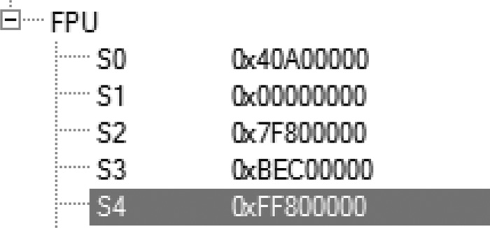
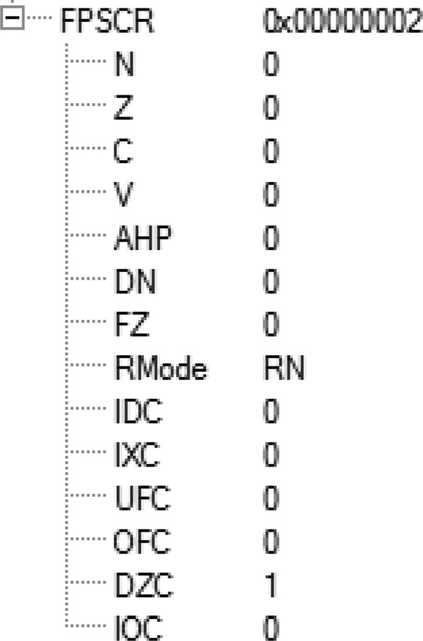
The result of the first division in register s2 is a positive infinity (convince yourself that this is the hexadecimal pattern for a positive infinity), and the result in register s4 is a negative infinity (again, make sure you are convinced that this is a negative infinity).
What if the dividend was not a normal or subnormal value? If it was a zero, NaN, or an infinity, there is no commonly accepted mathematical result for this situation. An Invalid Operation exception is returned, and the division by zero exception is not signaled. We will consider this exception next.
10.3.4 Invalid Operation
There are a host of conditions that will signal an Invalid Operation exception. Most are present to signal mathematical situations for which a commonly accepted result is not known, such as the division of zero by zero, as mentioned above. The conditions for Invalid Operation fall into three categories:
- Operations with signaling NaNs (sNANs)—Of the two types of NaNs discussed in Section 9.6.5, the sNaN, or signaling NaN, will always signal the Invalid Operation exception when operated on by an arithmetic operation. Note that data moves will not trigger the exception. No other exceptions are signaled for an operation involving a sNaN, even if other exceptional conditions exist.
- Arithmetic operations without a commonly accepted default result—Several operations simply don’t have agreed upon results. Consider addition with unlike-signed infinities and multiplication of infinity by zero. These operations are defined as “undefined,” or an “indefinite form.” The complete list is given in Table 10.6 for floating-point operations; however, other operations that are not specified by the standard, such as transcendental functions, may also raise exception flags.
- Conversion operations—When a conversion of a value in floating-point format to an integer or fixed-point format isn’t possible because the value of the floating-point operand is too large for that destination format, the Invalid Operation exception is signaled. For example, if register s4 contains 0x60000000 (~3.7 × 10¹⁵), conversion to a 32-bit integer would not be possible, since this value is much greater than is representable. In this case the largest integer value is returned, and the IOC and IXC bits are set in the FPSCR. Again, this is because there is no integer format that would indicate the error. All bit patterns in the integer formats represent valid numbers, and to return even the maximum value would not represent the input value or indicate the error condition. Why not use the Overflow exception for this case? The Overflow exception indicates the result of an arithmetic operation, and this is a format conversion issue and not an arithmetic operation.
When the Invalid Operation exception is detected for arithmetic and conversion operations, the default Quiet NaN (qNaN) is returned and the Invalid Operation (IOC) status bit is set in the FPSCR. The format of the default NaN is at the implementer’s discretion; in Section 9.8.1.1 we saw what the developers of the Cortex-M4 chose as the default NaN. When an input is a sNaN, the sNaN is quieted, that is, the NaN type bit is set, making the sNaN into a qNaN. If more than one input operand is a NaN of either flavor, one of the NaNs will be returned, but always in a quiet form.
Operations and Operands Signaling the Invalid Operation Exception
|
Instruction |
Invalid Operation Exceptions |
|
VADD |
(+infinity) + (−infinity) or (−infinity) + (+infinity) |
|
VSUB |
(+infinity) − (+infinity) or (−infinity) − (−infinity) |
|
VCMPE, VCMPEZ |
Any NaN operand |
|
VMUL, VNMUL |
Zero × ±infinity or ±infinity × zero |
|
VDIV |
Zero/zero or infinity/infinity |
|
VMAC, VNMAC |
Any condition that can cause an Invalid Operation exception for VMUL or VADD can cause an Invalid Operation exception for VMAC and VNMAC. The product generated by the VMAC or VNMAC multiply operation is considered in the detection of the Invalid Operation exception for the subsequent sum operation |
|
VMSC, VNMSC |
Any of the conditions that can cause an Invalid Operation exception for VMUL or VSUB can cause an Invalid Operation exception for VMSC and VNMSC. The product generated by the VMSC or VNMSC multiply operation is considered in the detection of the Invalid Operation exception for the subsequent difference operation |
|
VSQRT |
Source is less than 0 |
|
VMLA/VMLS |
Multiplier and multiplicand are zero and infinity or infinity and zero |
|
VMLA/VMLS |
The product overflows and the addend is an infinity, and the sign of the product is not the sign of the addend |
|
Convert FP to Int |
Source is NaN, Inf, or outside the range with RMode |
10.3.5 Overflow
The Overflow exception is signaled when the result of an arithmetic operation cannot be represented because the absolute value of the result is too large for the destination format. In this way it is possible to overflow both with a positive and a negative result. In the default RNE rounding mode, a positive value too large for the single-precision format will return a positive infinity. Likewise, if the absolute value of the result is too large for the single-precision format, and the sign is negative, a negative infinity will be returned. In the general case, the default value returned depends on the signs of the operands and the rounding mode, as seen in Table 10.7. One thing to note here is that with an overflow exception both the overflow status bit (OFC) and the inexact status bit (IXC) are set.
Default Values for the Overflow Exception
|
Rounding Mode |
Positive Result |
Negative Result |
|
RNE |
+ infinity |
− infinity |
|
RP |
+ infinity |
− maximum normal value |
|
RM |
+ maximum normal value |
− infinity |
|
RZ |
+ maximum normal value |
− maximum normal value |
If you consider that the default rounding mode is RNE, returning positive and negative infinity values for overflows makes very good sense. Likewise, for the three directed rounding modes, returning the largest normal value indicates rounding in one direction, while infinity indicates rounding in the other direction. Overflow is possible in most arithmetic operations. Take note, overflow may be due to the operation resulting in a value outside the range before rounding, or it may be due to a pre-rounded result that is in the normal range but the rounded result overflows. The case of a pre-rounded result rounding to an overflow condition is left as an exercise.
Example 10.7
Compute the factorial function for all integers from 1 to 35.
Solution
The factorial computation is
or by the recurrence relation
We can construct a simple table of factorials, beginning with the factorial of 1 and continue until we have a factorial too large to fit in a single-precision value.
1 - 1
2 - 2
3 - 6
4 - 24
…
10 - 3,628,800, or 3.628 × 10⁶
…
15 - 1,307,674,368,000, or 1.307 × 10¹²
…
20 - 2,432,902,008,176,640,000, or 2.432 × 10¹⁸
…
25 - 15,511,210,043,330,985,984,000,000, or 1.551 × 1025
…
30 - 265,252,859,812,191,058,636,308,480,000,000, or 2.653 × 1032
31 - 8,222,838,654,177,922,817,725,562,880,000,000, or 8.223 × 1033
32 - 263,130,836,933,693,530,167,218,012,160,000,000, or 2.632 × 1035
33 - 8,683,317,618,811,886,495,518,194,401,280,000,000, or 8.683 × 1036
34 - 295,232,799,039,604,140,847,618,609,643,520,000,000, or 2.952 × 1038
35 - 10,333,147,966,386,144,929,666,651,337,523,200,000,000, or 1.033 × 1040
Recalling that the range of a single-precision value is up to 3.40 × 1038, the factorial of 35 will result in a value too large for the single-precision format. According to Table 10.2, the result for the roundTiesToEven rounding mode and the roundTowardPositive rounding mode is a +infinity, while the roundTowardNegative and roundTowardZero would return the maximum normal value, or 3.40 × 1038 (0x7F7FFFFF). If we attempted to compute the factorial of 36 by multiplying the computed value of 35! by 36, we would get back the same value as computed for 35!. Why? In RNE and RP modes, we are multiplying +infinity by 36, which results in +infinity, and in RM and RP modes, the value of the maximum normal value multiplied by 36 again overflows, and the maximum normal value will be returned. Showing this in simulation is left as an exercise.
10.3.6 Underflow
Floating-point arithmetic operations can also underflow when the result of the operation is too small to fit in the destination format. You can imagine when two very small values, say 6.6261 × 10⁻³⁴ (Planck’s constant in J ⋅ s) and 1.602 × 10⁻¹⁹ (elementary charge in Coulombs), are multiplied, the product is 10.607 × 10−53, but this value is outside the normal range of a single-precision value, and we have underflowed. In some systems the result would be a signed zero.** Underflow is unique among the exceptions in that it is at the discretion of the processor designer whether the determination of underflow is made before rounding or after rounding, but all underflow determinations must be made the same way. The Cortex-M4 chose to detect underflow before rounding. When the Underflow exception is detected, the default value returned is a subnormal value (if the result is within the subnormal range for the destination precision) or a signed zero. The Underflow status bit (UFC) and the Inexact status bit (IXC) are set in the FPSCR if the result is not exact; otherwise, neither status bit is set. For example, if the operation resulted in a subnormal value that was exact, neither the UFC or IXC bits will be set. The IEEE 754-2008 standard does not regard this as an underflow condition. However, if the result is subnormal and not exact, both the UFC and IXC bits will be set, since the result is below the normal range and inexact. In the same way, if the result is too small even to be represented as a subnormal, and a zero is returned, both the UFC and IXC bits will be set, since this is both an underflow and an inexact condition. Table 10.8 summarizes the several cases possible in underflow condition.
Summary of the Flags and Results in Underflow Conditions
|
Result before Rounding |
Returned Result |
Flags Set |
|
Subnormal range |
Subnormal value |
If exact, no flags. Otherwise, UFC and IXC |
|
Below subnormal range |
Signed zero |
UFC and IXC |
10.3.7 Inexact Result
As we saw in the section on rounding, not all floating-point computations are exact. More likely than not, most will result in an intermediate value which is between two representable values and requires rounding. When this occurs, the result is said to be inexact. That means simply that there was no representable value exactly matching the result, and another value was substituted for the computed result. When the Inexact Exception occurs, the Inexact flag (IXC) is set in the FPSCR and the computation continues. The programmer may check this flag at any time to see whether any of the operations returned an inexact result since the last time the flag was cleared.
10.4 Algebraic Laws and Floating-Point
In school we were taught several laws of mathematics, and we’re interested in three of these, namely the commutative law, the associative law, and the distributive law. Are they still useful in the world of floating-point? Let’s take each one separately. The commutative law states that in addition and multiplication the operands may be swapped without affecting the answer. Such is not the case for subtraction and division. Does this law hold for floating-point addition and multiplication? Consider the following.
Example 10.8
If register s7 contains 0x40200000 (2.5) and register s8 contains 0x42FD999A (126.8), will these two instructions produce the same result? You should try this for yourself.
VADD.F32 s10, s7, s8
VADD.F32 s11, s8, s7
Likewise, consider these instructions:
VMUL.F32 s12, s7, s8
VMUL.F32 s13, s8, s7
Is the value in register s10 the same as in register s11, and the value in register s12 the same as register s13? They do indeed have the same values, and we can expect that in all cases floating-point addition and multiplication abide by the commutative property. Note, however, that this applies only to a single addition or multiplication operation. When more than two operands are to be summed or multiplied, the IEEE 754-2008 standard requires the operations be performed in the order of the program code unless rearranging the operands would return the same result value and flags.
What about the associative law? If A, B, and C are single-precision floating-point values, is
(A + B) + C = A + (B + C)
as required by the associative property of addition? If we denote floating-point addition of single-precision values with a single-precision result as ⊕, is
(A ⊕ B) ⊕ C = A ⊕ (B ⊕ C)?
Consider the example below.
Example 10.9
Let A be 0x50800000 (1.718 × 10¹⁰) in register s13, let B be 0xD0800000 (−1.718 × 10¹⁰) in register s14, and let C be 0x2FC00000 (3.492 × 10⁻¹⁰) in register s15. What is the result of the following pair of instructions?
VADD.F32 s16, s13, s14 ; s13 = A, s14 = B, s16 = A ⊕ B
VADD.F32 s17, s16, s15 ; s15 = C, s17 = (A ⊕ B) ⊕ C
Is it different from this pair of instructions?
VADD.F32 s16, s14, s15 ; s16 = (B ⊕ C)
VADD.F32 s17, s13, s16 ; s17 = A ⊕ (B ⊕ C)
In this example A ⊕ B is zero, so the result of the first set of instructions is the value C in register s15, or 3.492 × 10⁻¹⁰. However, when B and C are added, the result is B, since the contribution of C is too small and is lost in the rounding of the VADD operation. So the result of the second set of operations is zero! While it is not always the case that floating-point addition fails to satisfy the associative property of addition, it must be a consideration to a programmer that the order of addition operations may affect the final result.
Does the associative law hold for multiplication? If we again have 3 single-precision operands, A, B, and C, and floating-point multiplication is denoted by ⊗, is the following true in all cases?
(A ⊗ B) ⊗ C = A ⊗ (B ⊗ C)
Example 10.10
Let A be 0x734C0000 (1.616 × 1031) in register s20, let B be 0x5064E1C0 (1.536 × 10¹⁰) in register s21, and let C be 0x2BF92000 (1.770 × 10⁻¹²) in register s22. What will be the answer for each of the following pairs of instructions?
VMUL.F32 s23, s20, s21 ; s20 = A, s21 = B, s23 = A ⊗ B
VMUL.F32 s24, s23, s22 ; s22 = C, s24 = (A ⊗ B) ⊗ C
and
VMUL.F32 s25, s21, s22 ; s25 = B ⊗ C
VMUL.F32 s26, s20, s23 ; s26 = A ⊗ (B ⊗ C)
In the first pair, A multiplied by B returns positive infinity (0x7F800000), and the second multiplication with C results in a positive infinity. The first multiplication overflows, and the second multiplication of a normal value and an infinity returns an infinity. However, in the second pair of instructions, B and C are multiplied first and results in 2.719 × 10⁻². When this product is multiplied by A, the result is 4.395 × 1029. All products in the second sequence of instructions are normal numbers; none of the products is an infinity. As with addition, the order of operands can play a critical role in the result of a series of additions or multiplications. When a result is not what is expected, as in the case of the infinity in the pair of multiplications, it is often a clue that the operand ordering played a part in the result.
This leaves the distributive law, which states that
A * (B + C) = (A * B) + (A * C)
From the above it should be clear that in floating-point operations this property can quite easily be shown to fail. This is left as an exercise for the reader.
10.5 Normalization and Cancelation
Often a floating-point computation will not be normalized, that is, it will not be in the correct form in the equation for a normal or subnormal value. It could be so because the computed significand is in the range [2.0, 4.0). To normalize the result, it must be shifted right one place, and the exponent must be incremented to be within the proper range. For example, if we multiply
1.7 (0x3FD9999A) × 1.4 (0x3FB33333) = 2.38 (0x401851EC)
you notice that both input operands have the exponent 0x3F8 (representation of 20); however, the result has the exponent 0x400 (representation of 21). Internally, the product of 1.7 and 1.4 results in a significand in the range [2.0, 4.0), specifically, 2.38. To form the final result value, the Cortex-M4 shifts the internal significand to the right 1 place to form a new significand of 1.19, and increments the exponent (then 0) to 1, and forms the result as
2.38 = −10 × 21 × 1.19
This is referred to as post-normalization and is all done internal to the processor—it’s invisible to the user. Once the computed result is normalized, the guard and sticky bits can be generated. Similarly, in the case of an effective subtraction, it is possible for the upper bits to cancel out, leaving a string of zeros in the most significant bit positions. An effective subtraction is a subtraction operation on like signed operands, that is,
(+1.0) – (+0.45) or (−5.3) – (−2.1),
or an addition of unlike signed operands, such as
(+1.0) + (−0.45) or (+5.3) + (−2.1).
Any summation operation that produces a result closer to 0 is an effective subtraction.
Example 10.11
Consider in this decimal example
1.254675 × 10⁶ – 1.254533 × 106 = 1.42 × 10²
Most of the upper digits cancel out, leaving only a value with an order of magnitude of 2 when the original operands were order of magnitude 6. This may occur when the exponents of the two operands in an effective subtraction are equal or differ by 1. The same situation occurs for floating-point, requiring the resulting significand to be left shifted until a 1 appears in the integer bit of the result, and the exponent must be decremented accordingly.
Example 10.12
Add 0x3F9CE3BD and 0xBF9CD35B.
Solution
Let OpA be 0x3F9CE3BD (1.2257) and OpB be 0xBF9CD35B (−1.2252). If the value in register s3 is OpA and register s4 contains OpB, and these are added in the FPU with the instruction
VADD.F32 s5, s3, s4
the result in register s5 will be 0x3A031000 (4.9996 × 10⁻⁴, the closest representation in single-precision to 5.0 × 10⁻⁴). Notice the exponent has been adjusted so the resulting significand is in the range [1.0, 2.0), as we saw with the multiplication and decimal examples above. Table 10.9 shows this process. The two operands are normalized (the leading binary bit is a 1). When subtracted, the upper bits cancel, leaving a string of zeros before the first 1. To normalize the significand, we shift it left until the most significant bit is a 1. The number of shift positions is 11, since the number of leading zeros is 11. To generate the final exponent, the initial exponent (0x7F) is decremented by 11, resulting in the final exponent of 0x74. The final result in single-precision format is 0x3A031000. Verify for yourself that the four results in binary in Table 10.9 are correct.
Internal Values for Example 10.12
|
Exponent |
Significand |
|
|
OpA (Addend) |
01111111 |
100111001110001110111100 |
|
OpA (Addend) |
01111111 |
100011001101001101011011 |
|
Sum (pre-normalized) |
01111111 |
000000000001000001100010 |
|
Post-normalized sum |
01110100 |
100000110001000000000000 |
|
Result sum − RNE |
01110100 |
100000110001000000000000 |
|
Result sum − RP |
01110100 |
100000110001000000000000 |
|
Result sum − RM |
01110100 |
100000110001000000000000 |
|
Result sum − RZ |
01110100 |
100000110001000000000000 |
When a result is computed and the exponent is incremented or decremented, it may result in an overflow or underflow condition.
Example 10.13
Multiply 0x3F800001 by 0x7F7FFFFE in each rounding mode.
Solution
In this example, the rounding of the internal infinitely precise product results in an overflow of the significand, and the exponent is incremented in the normalization of the final significand. When the exponent is incremented, it becomes too large for the single-precision format, and the final product overflows.
In Table 10.10, the OpA value is the multiplier and the OpB value is the multiplicand. Only two bits are set in the multiplier—OpA[0] and OpA[23] so there will only be two partial products to be summed. The infinitely precise product is all ones, except the final bit, and the L, G, and S rounding bits are each one. In the roundTiesToEven and roundTowardPositive rounding modes, this causes a rounding increment, which is done by adding a one to the bit in the L position. When the infinitely precise product is incremented, the resulting internal product is
Internal Values for Example 10.13
|
Operand Significand |
|||||
|
OpB Significand (Multiplicand) |
1 |
111 |
11111111111111111110 |
||
|
OpA Significand (Multiplier) |
1 |
000 |
00000000000000000001 |
||
|
Infinitely-precise internal significand |
|||||
|
OpA[0] term |
1 |
111 |
11111111111111111110 |
||
|
OpA[23] term |
1.111 |
1111111111111111 |
1110 |
||
|
Infinitely-precise internal significand |
|||||
|
Infinitely precise product |
1.111 |
1111111111111111 |
1111 |
111 |
11111111111111111110 |
|
Pre-rounded product |
1.111 |
1111111111111111 |
111L |
Gss |
ssssssssssssssssssss |
|
Incremented product |
10.000 |
0000000000000000 |
0000 |
111 |
11111111111111111110 |
|
Result significand |
|||||
|
Result product - RNE |
1.000 |
0000000000000000 |
0000 |
||
|
Result product – RP |
1.000 |
0000000000000000 |
0000 |
||
|
Result product – RM |
1.111 |
1111111111111111 |
1111 |
||
|
Result product – RZ |
1.111 |
1111111111111111 |
1111 |
||
10.0000000000000000000000011111111111111111111110
which is greater than 2.0, as shown in the line Incremented product in Table 10.10. To normalize this significand to the range [1.0, 2.0), it is shifted right one place and the exponent is incremented by one. Only the upper 24 bits are returned; the lower bits, which contribute to the rounding determination, are discarded. The exponent before the increment is 0xFE, the largest normal exponent. When incremented, the resulting exponent is 0xFF, which is too large to be represented in single-precision, and an infinity is returned. In the roundTowardNegative and roundTowardZero rounding modes the increment is not required, and the pre-rounded product is normalized and within the bounds of single-precision range.
It is also possible to round out of an underflow condition. Recall that the Cortex-M4 will signal underflow if the intermediate result is below the minimum normal range and imprecise, even if rounding would return the minimum normal value.
Example 10.14
Multiply 0x3F000001 and 0x00FFFFFF in each rounding mode.
Solution
In this example, the two significands are exactly the same as in the previous example, resulting in the same infinitely precise product and rounding conditions. As we saw in the previous example, in the roundTiesToEven and roundTowardPositive rounding modes this causes a rounding increment. In this case the exponent before the rounding was 0x00, one less than is representable by a normal value. When the infinitely precise product is incremented, the resulting internal product is again 2.0, and the normalization results in a new exponent of 0x01, the smallest exponent for normal numbers. The result for the roundTiesToEven and roundTowardPositive is the smallest normal number, 0x00800000, and underflow is signaled with IXC. However, for roundTowardNegative and roundTowardZero, no increment is required and the result is 0x007FFFFF, in the subnormal range, and UFC and IXC are signaled.
10.6 Exercises
- For each rounding mode, show the resulting value given the sign, exponent, fraction, guard, and sticky bit in the cases below.
Rounding Mode
Sign
Exponent
Fraction
G bit
S bit
0
011111111
11111111111111111111111
1
0
roundTiesToEven
roundTowardPositive
roundTowardNegative
roundTowardZero
1
000000000
11111111111111111111111
0
1
roundTiesToEven
roundTowardPositive
roundTowardNegative
roundTowardZero
0
11111110
11111111111111111111111
1
1
roundTiesToEven
roundTowardPositive
roundTowardNegative
roundTowardZero
1
11111110
01111111111111111111110
1
0
roundTiesToEven
roundTowardPositive
roundTowardNegative
roundTowardZero
- Rework Example 10.1 with the following values for OpB. For each, generate the product rounded for each of the four rounding modes:
- 0xc4900000
- 0xc4800000
- 0xc4b00000
- 0xc4c00000
- 0x34900000
- 0x34800000
- 0x34b00000
- 0x34c00000
- Complete the following table for the given operands and operations, showing the result and the exception status bits resulting from each operation. Assume the multiply-accumulate operations are fused.
Operation
Operand A
Operand B
Operand C
Result
Exception Bit(s) set
A + B
0xFF800000
0x7F800000
—
A * B
0x80000000
0x7F800000
—
A – B
0xFF800000
0xFF800001
—
A/B
0x7FC00011
0x00000000
—
A/B
0xFF800000
0xFF800000
—
A * B
0x10500000
0x02000000
—
A * B
0x01800000
0x3E7FFFFF
—
A * B
0x3E7F0000
0x02000000
—
(A * B) + C
0x80000000
0x00800000
0x7FB60004
(A * B) + C
0x3F800000
0x7F800000
0xFF800000
(A * B) + C
0x6943FFFF
0x71000000
0xFF800000
- Write a program in a high-level language to input two single-precision values and add, subtract, multiply and divide the values. In this Exercise use the default rounding mode. Test your program with various floating-point values.
- Using routines available in your high-level language, perform each of the computations in each of the four rounding modes. In C, you can use the floating-point environment by including <fenv.h> and changing the rounding mode by the function fsetround(RMODE), where RMODE is one of
FE_DOWNWARD
FE_TONEAREST
FE_TOWARDZERO
FE_UPWARD
- Test your program with input values, modifying the lower bits in the operands to see how the result differs for the four rounding modes. For example, use 0x3f800001 and 0xbfc00000. What differences did you notice in the results for the four rounding modes?
- Give 3 values that will hold to the distributive law and 3 which will not.
- Is it is possible to have cancelation in an effective subtraction operation and have a guard and sticky bit? If so, show an example. If not, explain why.
- Demonstrate that the distributive law can fail to hold for floating-point values.
- Redo Example 10.4 using 0x3F800003 as the multiplier.
- Show that 36! generates an overflow condition.
- Demonstrate a case in which a multiply operation results in a normal value for the RZ and RN rounding modes, but overflows for the RNE and RP rounding modes.
** It doesn’t really keep an infinite set of bits from a computation. That would make for a really large processor. Rather, the computation is done as if to infinite precision, meaning that internal to the Cortex-M4 the computation retains enough information to round the result correctly. See the IEEE 754-2008 standard section 5.1, p. 17.
†* In the IEEE 754-1985 specification this referred to as Round to Nearest Even, hence RNE. The abbreviations of the other rounding modes should be self-explanatory.
‡† The IEEE 754-2008 Standard does not require roundTiesToAway (RNA). See Clause 4.3.3, p. 16.
§* A ulp is shorthand for a unit-in-the-last-place, or the bit with the smallest contribution to the final result. For single-precision, this is the least significant bit. This is a common term in floating-point error analysis.
¶* The IEEE 754-2008 standard specifies an Alternate exception handling mechanism in which a trap is taken to a trap handler, which allows the programmer to specify the behavior to be taken when the exception is detected. The Cortex-M4 does not allow for this option directly, but instead provides five pins on the boundary of the processor core that toggle with the exception flag. Each could be connected to an interrupt input and cause an interrupt routine to execute when the exception is signaled.
*** We will see this option in the Cortex-M4 in the Flush-to-zero mode described in Section 11.5.1.