Table of Contents for
Modern Assembly Language Programming with the ARM Processor
 Modern Assembly Language Programming with the ARM Processor
Published by
Newnes, 2016
Modern Assembly Language Programming with the ARM Processor
Published by
Newnes, 2016
- Modern Assembly Language Programming with the ARM Processor
- Cover image
- Title page
- Table of Contents
- Copyright
- List of Tables
- List of Figures
- List of Listings
- Preface
- Companion Website
- Acknowledgments
- Part I: Assembly as a Language
- Chapter 1: Introduction
- Chapter 2: GNU Assembly Syntax
- Chapter 3: Load/Store and Branch Instructions
- Chapter 4: Data Processing and Other Instructions
- Chapter 5: Structured Programming
- Chapter 6: Abstract Data Types
- Part II: Performance Mathematics
- Chapter 7: Integer Mathematics
- Chapter 8: Non-Integral Mathematics
- Chapter 9: The ARM Vector Floating Point Coprocessor
- Chapter 10: The ARM NEON Extensions
- 10.10 Multiplication and Division
- Part III: Accessing Devices
- Chapter 11: Devices
- Chapter 12: Pulse Modulation
- Chapter 13: Common System Devices
- Chapter 14: Running Without an Operating System
- Index
Running Without an Operating System
Abstract
This chapter starts by describing the extra responsibilities that the programmer must assume when writing code to run without an operating system (bare metal). It then explains privileged and user modes and describes all of the privileged modes available on the ARM processor. Next, it gives an overview of exception processing, and provides example code for setting up the vector table stubs for exception handling functions on the ARM processor. Next, it describes the boot processes on the Raspberry Pi and the pcDuino. After that, it shows how to write a basic bare metal program, without any exception processing. The chapter finishes by showing a more efficient version of the bare metal program using an interrupt.
Keywords
Bare metal; Exception; Vector table; Exception handler; Sleep mode; User mode; Privileged mode; Startup code; Linker script; Boot loader; Interrupt
The previous chapters assumed that the software would be running in user mode under an operating system. Sometimes, it is necessary to write assembly code to run on “bare metal,” which simply means: without an operating system. For example, when we write an operating system kernel, it must run on bare metal and a significant part of the code (especially during the boot process) must be written in assembly language. Coding on bare metal is useful to deeply understand how the hardware works and what happens in the lowest levels of an operating system. There are some significant differences between code that is meant to run under an operating system and code that is meant to run on bare metal.
The operating system takes care of many details for the programmer. For instance, it sets up the stack, text, and data sections, initializes static variables, provides an interface to input and output devices, and gives the programmer an abstracted view of the machine. When accessing data on a disk drive, the programmer uses the file abstraction. The underlying hardware only knows about blocks of data. The operating system provides the data structures and operations which allow the programmer to think of data in terms of files and streams of bytes. A user program may be scattered in physical memory, but the hardware memory management unit, managed by the operating system, allows the programmer to view memory as a simple memory map (such as shown in Fig. 1.7). The programmer uses system calls to access the abstractions provided by the operating system. On bare metal, there are no abstractions, unless the programmer creates them.
However, there are some software packages to help bare-metal programmers. For example, Newlib is a C standard library intended for use in bare-metal programs. Its major features are that:
• it implements the hardware-independent parts of the standard C library,
• for I/O, it relies on only a few low-level functions that must be implemented specifically for the target hardware, and
• many target machines are already supported in the Newlib source code.
To support a new machine, the programmer only has to write a few low-level functions in C and/or Assembly to initialize the system and perform low-level I/O on the target hardware.
14.1 ARM CPU Modes
Many early computers were not capable of protecting the operating system from user programs. That problem was solved mostly by building CPUs that support multiple “levels of privilege” for running programs. Almost all modern CPUs have the ability to operate in at least two modes:
User mode is the mode that normal user programs use when running under an operating system, and
Privileged mode is reserved for operating system code. There are operations that can be performed in privileged mode which cannot be performed in user mode.
The ARM processor provides six privileged modes and one user mode. Five of the privileged modes have their own stack pointer (r13) and link register (r14). When the processor mode is changed, the corresponding link register and stack pointer become active, “replacing” the user stack pointer and link register.
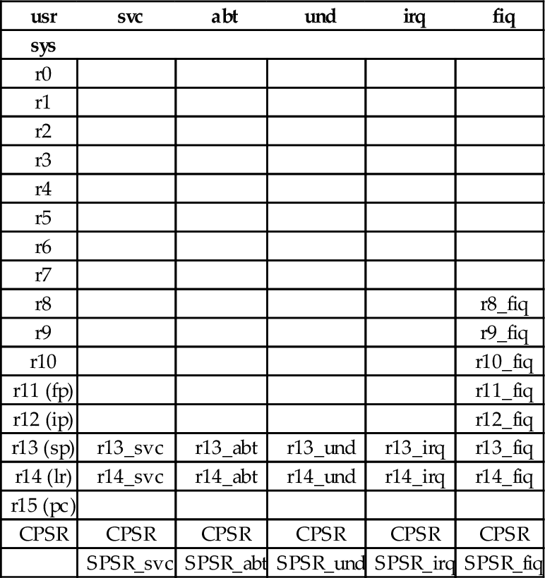
In any of the six privileged modes, the link registers and stack pointers of the other modes can be accessed. The privileged mode stack pointers and link registers are not accessible from user mode. One of the privileged modes, FIQ, has five additional registers which become active when the processor enters FIQ mode. These registers “replace” registers r8 through r12. Additionally, five of the privileged modes have a Saved Process Status Register (SPSR). When entering those privileged modes, the CPSR is copied into the corresponding SPSR. This allows the CPSR to be restored to its original contents when the privileged code returns to the previously active mode. The full register set for all modes is shown in Table 14.1. Registers r0 through r7 and the program counter are shared by all modes. Some processors have an additional monitor mode, as part of the ARMv6-M and ARMv7-M security extensions.
Table 14.1
The ARM user and system registers
| usr | svc | abt | und | irq | fiq |
| sys | |||||
| r0 | |||||
| r1 | |||||
| r2 | |||||
| r3 | |||||
| r4 | |||||
| r5 | |||||
| r6 | |||||
| r7 | |||||
| r8 | r8_fiq | ||||
| r9 | r9_fiq | ||||
| r10 | r10_fiq | ||||
| r11 (fp) | r11_fiq | ||||
| r12 (ip) | r12_fiq | ||||
| r13 (sp) | r13_svc | r13_abt | r13_und | r13_irq | r13_fiq |
| r14 (lr) | r14_svc | r14_abt | r14_und | r14_irq | r14_fiq |
| r15 (pc) | |||||
| CPSR | CPSR | CPSR | CPSR | CPSR | CPSR |
| SPSR_svc | SPSR_abt | SPSR_und | SPSR_irq | SPSR_fiq |
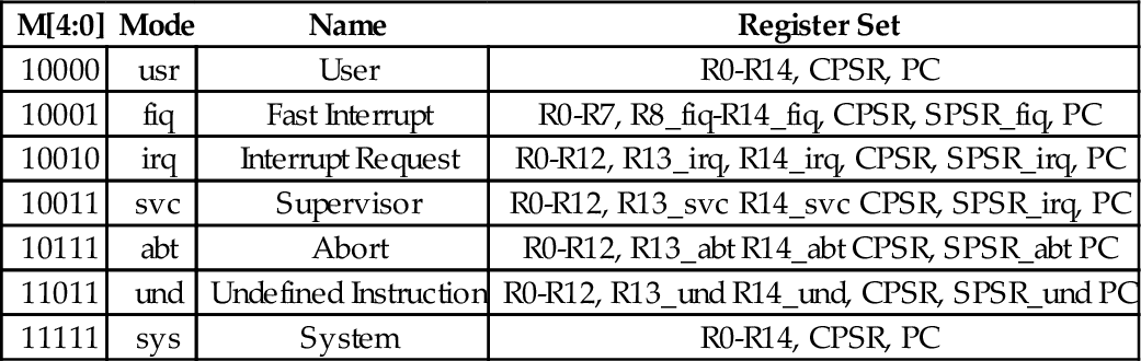
All of the bits of the Program Status Register (PSR) are shown in Fig. 14.1. The processor mode is selected by writing a bit pattern into the mode bits (M[4:0]) of the PSR. The bit pattern assignment for each processor mode is shown in Table 14.2. Not all combinations of the mode bits define a valid processor mode. An illegal value programmed into M[4:0] causes the processor to enter an unrecoverable state. If this occurs, a hardware reset must be used to re-start the processor. Programs running in user mode cannot modify these bits directly. User programs can only change the processor mode by executing the software interrupt (swi) instruction (also known as the svc instruction), which automatically gives control to privileged code in the operating system. The hardware is carefully designed so that the user program cannot run its own code in privileged mode.

Table 14.2
Mode bits in the PSR
| M[4:0] | Mode | Name | Register Set |
| 10000 | usr | User | R0-R14, CPSR, PC |
| 10001 | fiq | Fast Interrupt | R0-R7, R8_fiq-R14_fiq, CPSR, SPSR_fiq, PC |
| 10010 | irq | Interrupt Request | R0-R12, R13_irq, R14_irq, CPSR, SPSR_irq, PC |
| 10011 | svc | Supervisor | R0-R12, R13_svc R14_svc CPSR, SPSR_irq, PC |
| 10111 | abt | Abort | R0-R12, R13_abt R14_abt CPSR, SPSR_abt PC |
| 11011 | und | Undefined Instruction | R0-R12, R13_und R14_und, CPSR, SPSR_und PC |
| 11111 | sys | System | R0-R14, CPSR, PC |
The swi instruction does not really cause an interrupt, but the hardware and operating system handle it in a very similar way. The software interrupt is used by user programs to request that the operating system perform some task on their behalf. Another general class of interrupt is the “hardware interrupt.” This class of interrupt may occur at any time and is used by hardware devices to signal that they require service. Another type of interrupt may be generated within the CPU when certain conditions arise, such as attempting to execute an unknown instruction. These are generally known as “exceptions” to distinguish them from hardware interrupts. On the ARM processor, there are three bits in the CPSR which affect interrupt processing:
I: when set to one, normal hardware interrupts are disabled,
F: when set to one, fast hardware interrupts are disabled, and
A: (only on ARMv6 and later processors) when set to one, imprecise aborts are disabled (this is an abort on a memory write that has been held in a write buffer in the processor and not written to memory until later, perhaps after another abort).
Programs running in user mode cannot modify these bits. Therefore, the operating system gains control of the CPU whenever an interrupt occurs and the user program cannot disable interrupts and continue to run. Most operating systems use a hardware timer to generate periodic interrupts, thus they are able to regain control of the CPU every few milliseconds.
14.2 Exception Processing
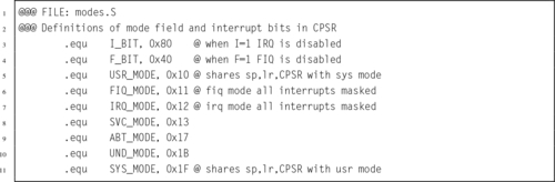
Most of the privileged modes are entered automatically by the hardware when certain exceptional circumstances occur. For example, when a hardware device needs attention, it can signal the processor by causing an interrupt. When this occurs, the processor immediately enters IRQ mode and begins executing the IRQ exception handler function. Some devices can cause a fast interrupt, which causes the processor to immediately enter FIQ mode and begin executing the FIQ exception handler function. There are six possible exceptions that can occur, each one corresponding to one of the six privileged modes. Each exception must be handled by a dedicated function, with one additional function required to handle CPU reset events. The first instruction of each of these seven exception handlers is stored in a vector table at a known location in memory (usually address 0). When an exception occurs, the CPU automatically loads the appropriate instruction from the vector table and executes it. Table 14.3 shows the address, exception type, and the mode that the processor will be in, for each entry in ARM vector table. The vector table usually contains branch instructions. Each branch instruction will jump to the correct function for handling a specific exception type. Listing 14.1 shows a short section of assembly code which provides definitions for the ARM CPU modes.
Table 14.3
ARM vector table
| Address | Exception | Mode |
| 0x00000000 | Reset | svc |
| 0x00000004 | Undefined Instruction | und |
| 0x00000008 | Software Interrupt | svc |
| 0x0000000C | Prefetch Abort | abt |
| 0x00000010 | Data Abort | abt |
| 0x00000014 | Reserved | |
| 0x00000018 | Interrupt Request | irq |
| 0x0000001C | Fast Interrupt Request | fiq |
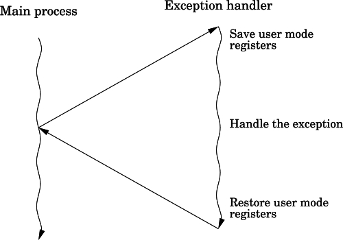
Many bare-metal programs consist of a single thread of execution running in user mode to perform some task. This main program is occasionally interrupted by the occurrence of some exception. The exception is processed, and then control returns to the main thread. Fig. 14.2 shows the sequence of events when an exception occurs in such a system. The main program typically would be running with the CPU in user mode. When the exception occurs, the CPU executes the corresponding instruction in the vector table, which branches to the exception handler. The exception handler must save any registers that it is going to use, execute the code required to handle the exception, then restore the registers. When it returns to the user mode process, everything will be as it was before the exception occurred. The user mode program continues executing as if the exception never occurred.
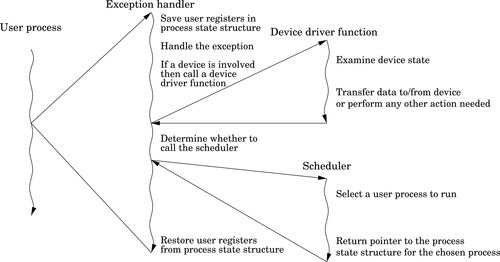
More complex systems may have multiple tasks, threads of execution, or user processes running concurrently. In a single-processor system, only one task, thread, or user process can actually be executing at any given instant, but when an exception occurs, the exception handler may change the currently active task, thread, or user process. This is the basis for all modern multiprocessing systems. Fig. 14.3 shows how an exception may be processed on such a system. It is common on multi-processing systems for a timer device to be used to generate periodic interrupts, which allows the currently active task, thread, or user process to be changed at a fixed frequency.
When any exception occurs, it causes the ARM CPU hardware to perform a very well-defined sequence of actions:
1. The CPSR is copied into the SPSR for the mode corresponding to the type of exception that has occurred.
2. The CPSR mode bits are changed, switching the CPU into the appropriate privileged mode.
3. The banked registers for the new mode become active.
4. The I bit of the CPSR is cleared, which disables interrupts.
5. If the exception was an FIQ, or if a reset has occurred, then the FIQ bit is cleared, disabling fast interrupts.
6. The program counter is copied to the link register for the new mode.
7. The program counter is loaded with the address in the vector table corresponding with the exception that has occurred.
8. The processor then fetches the next instruction using the program counter as usual. However, the program counter has been set so that in loads an instruction from the vector table.
The instruction in the vector table should cause the CPU to branch to a function which handles the exception. At the end of that function, the program counter must be loaded with the address of the instruction where the exception occurred, and the SPSR must be copied back into the CPSR. That will cause the processor to branch back to where it was when the exception occurred, and return to the mode that it was in at that time.
14.2.1 Handling Exceptions
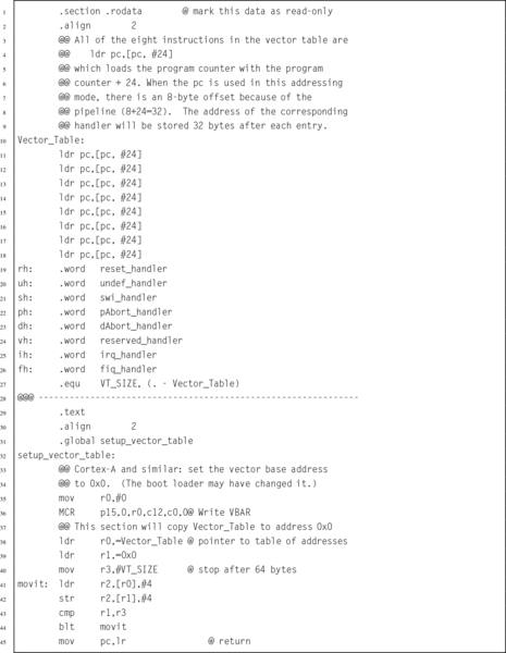
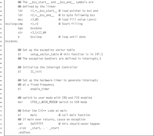
Listing 14.2 shows in detail how the vector table is initialized. The vector table contains eight identical instructions. These instructions load the program counter, which causes a branch. In each case, the program counter is loaded with a value at the memory location that is 32 bytes greater than the corresponding load instruction. An offset of 24 is used because the program counter will have advanced 8 bytes by the time the load instruction is executed. The addresses of the exception handlers have been stored in a second table, that begins at an address 32 bytes after the first load instruction. Thus, each instruction in the vector table loads a unique address into the program counter. Note that one of the slots in the vector table is not used and is reserved by ARM for future use. That slot is treated like all of the others, but it will never be used on any current ARM processor.
Listing 14.3 shows the stub functions for each of the exception handlers.
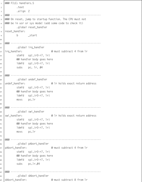
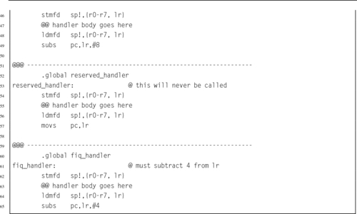
Note that the return sequence depends on the type of exception. For some exceptions, the return address must be adjusted. This is because the program counter may have been advanced past the instruction where the exception occurred. These stub functions simply return the processor to the mode and location at which the exception occurred. To be useful, they will need to be extended significantly. Note that these functions all return using a data processing instruction with the optional s specified and with the program counter as the destination register. This special form of data processing instruction indicates that the SPSR should be copied into the CPSR at the same time that the program counter is loaded with the return address. Thus, the function returns to the point where the exception occurred, and the processer switches back into the mode that it was in when the exception occurred.
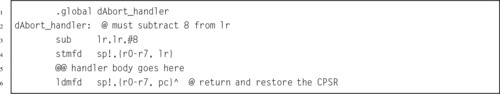
A special form of the ldm instruction can also be used to return from an exception processing function. In order to use that method, the exception handler should start by adjusting the link register (depending on the type of exception) and then pushing it onto the stack. The handler should also push any other registers that it will need to use. At the end of the function, an ldmfd is used to restore the registers, but instead of restoring the link register, it loads the program counter. Also a carat (ˆ) is added to the end of the instruction. Listing 14.4 shows the skeleton for an exception handler function using this method.
14.3 The Boot Process
In order to create a bare-metal program, we must understand what the processor does when power is first applied or after a reset. The ARM CPU begins to execute code at a predetermined address. Depending on the configuration of the ARM processor, the program counter starts either at address 0 or 0xFFFF0000. In order for the system to work, the startup code must be at the correct address when the system starts up.
On the Raspberry Pi, when power is first applied, the ARM CPU is disabled and the graphics processing unit (GPU) is enabled. The GPU runs a program that is stored in ROM. That program, called the first stage boot loader, reads the second stage boot loader from a file named (bootcode.bin) on the SD card. That program enables the SDRAM, and then loads the third stage bootloader, start.elf. At this point, some basic hardware configuration is performed, and then the kernel is loaded to address 0x8000 from the kernel.img file on the SD card. Once the kernel image file is loaded, a “b #0x8000” instruction is placed at address 0, and the ARM CPU is enabled. The ARM CPU executes the branch instruction at address 0, then immediately jumps to the kernel code at address 0x8000.
To run a bare-metal program on the Raspberry Pi, it is only necessary to build an executable image and store it as kernel.img on the SD card. Then, the boot process will load the bare-metal program instead of the Linux kernel image. Care must be taken to ensure that the linker prepares the program to run at address 0x8000 and places the first executable instruction at the beginning of the image file. It is also important to make a copy of the original kernel image so that it can be restored (using another computer). If the original kernel image is lost, then there will be no way to boot Linux until it is replaced.
The pcDuino uses u-boot, which is a highly configurable open-source boot loader. The boot loader is configured to attempt booting from the SD card. If a bootable SD card is detected, then it is used. Otherwise, the pcDuino boots from its internal NAND flash. In either case, u-boot finds the Linux kernel image file, named uImage, loads it at address 0x40008000, and then jumps to that location. The easiest way to run bare-metal code on the pcDuino is to create a duplicate of the operating system on an SD card, then replace the uImage file with another executable image. Care must be taken to ensure that the linker prepares the program to run at address 0x40008000 and places the first executable instruction at the beginning of the image file. If the SD card is inserted, then the bare-metal code will be loaded. Otherwise, it will boot normally from the NAND flash memory.
14.4 Writing a Bare-Metal Program
A bare-metal program should be divided into several files. Some of the code may be written in assembly, and other parts in C or some other language. The initial startup code, and the entry and exit from exception handlers, must be written in assembly. However, it may be much more productive to write the main program and the remainder of the exception handlers as C functions and have the assembly code call them.
14.4.1 Startup Code
Other than the code being loaded at different addresses, there is very little difference between getting bare-metal code running on the Raspberry Pi and the pcDuino. For either platform, the bare-metal program must include some start-up code. The startup code will:
• initialize the stack pointers for all of the modes,
• set up interrupt and exception handling,
• initialize the .bss section,
• configure the CPU and critical systems (optional),
• set up memory management (optional),
• set up process and/or thread management (optional),
• initialize devices (optional), and call the main function.
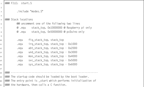
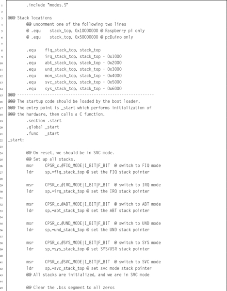
The startup code requires some knowledge of the target platform, and must be at least partly written in assembly language. Listing 14.5 shows a function named _start which sets up the stacks, initializes the .bss section, calls a function to set up the vector table, then calls the main function:
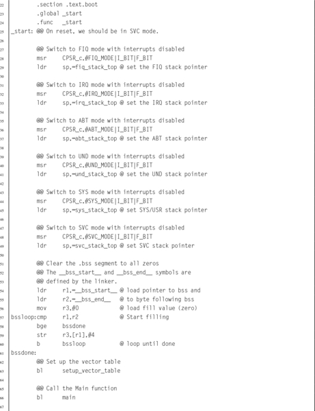

The first task for the startup code is to ensure that the stack pointer for each processor mode is initialized. When an exception or interrupt occurs, the processor will automatically change into the appropriate mode and begin executing an exception handler, using the stack pointer for that mode. Hardware interrupts can be disabled, but some exceptions cannot be disabled. In order to guarantee correct operation, a stack must be set up for each processor mode, and an exception handler must be provided. The exception handler does not actually have to do anything.
On the Raspberry Pi, memory is mapped to begin at address 0, and all models have at least 256 MB of memory. Therefore, it is safe to assume that the last valid memory address is 0x0FFFFFFF. If each mode is given 4 kB of stack space, then all of the stacks together will consume 32 kB, and the initial stack addresses can be easily calculated. Since the C compiler uses a full descending stack, the initial stack pointers can be assigned addresses 0x10000000, 0x0FFFF000, 0x0FFFE000, etc.
For the pcDuino, there is a small amount of memory mapped at address 0, but most of the available memory is in the region between 0x40000000 and 0xBFFFFFFF. The pcDuino has at least 1 GB of memory. One possible way to assign the stack locations is: 0x50000000, 0x4FFFF000, 0x4FFFE000, etc. This assignment of addresses will make it easy to write one piece of code to set up the stacks for either the Raspberry Pi or the pcDuino.
After initializing the stacks, the startup code must set all bytes in the .bss section to zero. Recall that the .bss section is used to hold data that is initialized to zero, but the program file does not actually contain all of the zeros. Programs running under an operating system can rely on the C standard library to initialize the .bss section. If it is not linked to a C library, then a bare-metal program must set all of the bytes in the .bss section to zero for itself.
14.4.2 Main Program
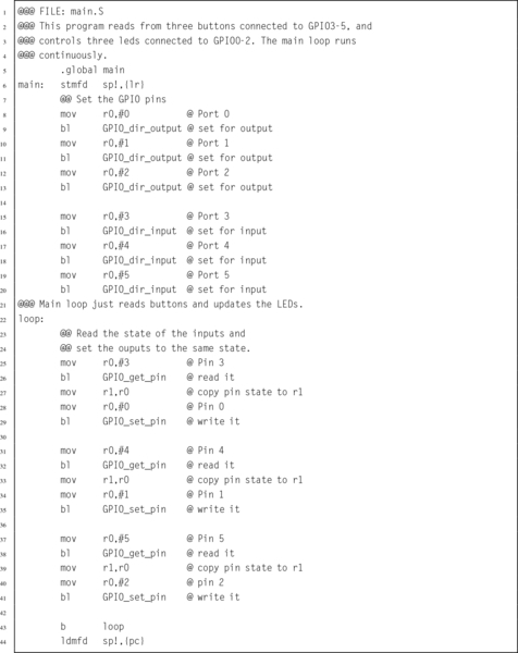
The final part of this bare-metal program is the main function. Listing 14.6 shows a very simple main program which reads from three GPIO pins which have pushbuttons connected to them, and controls three other pins that have LEDs connected to them. When a button is pressed the LED associated with it is illuminated. The only real difference between the pcDuino and Raspberry Pi versions of this program is in the functions which drive the GPIO device. Therefore, those functions have been removed from the main program file. This makes the main program portable; it can run on the pcDuino or the Raspberry Pi. It could also run on any other ARM system, with the addition of another file to implement the mappings and functions for using the GPIO device for that system.
14.4.3 The Linker Script
When compiling the program, it is necessary to perform a few extra steps to ensure that the program is ready to be loaded and run by the boot code. The last step in compiling a program is to link all of the object files together, possibly also including some object files from system libraries. A linker script is a file that tells the linker which sections to include in the output file, as well as which order to put them in, what type of file is to be produced, and what is to be the address of the first instruction. The default linker script used by GCC creates an ELF executable file, which includes startup code from the C library and also includes information which tells the loader where the various sections reside in memory. The default linker script creates a file that can be loaded by the operating system kernel, but which cannot be executed on bare metal.
For a bare-metal program, the linker must be configured to link the program so that the first instruction of the startup function is given the correct address in memory. This address depends on how the boot loader will load and execute the program. On the Raspberry Pi this address is 0x8000, and on the pcDuino this address is 0x40008000. The linker will automatically adjust any other addresses as it links the code together. The most efficient way to accomplish this is by providing a custom linker script to be used instead of the default system script. Additionally, either the linker must be instructed to create a flat binary file, rather than an ELF executable file, or a separate program (objcopy) must be used to convert the ELF executable into a flat binary file.
Listing 14.7 is an example of a linker script that can be used to create a bare-metal program. The first line is just a comment. The second line specifies the name of the function where the program begins execution. In this case, it specifies that a function named _start is where the program will begin execution. Next, the file specifies the sections that the output file will contain. For each output section, it lists the input sections that are to be used.

The first output section is the .text section, and it is composed of any sections whose names end in .text.boot followed by any sections whose names end in .text. In Listing 14.5, the _start function was placed in the .text.boot section, and it is the only thing in that section. Therefore the linker will put the _start function at the very beginning of the program. The remaining text sections will be appended, and then the remaining sections, in the order that they appear. After the sections are concatenated together, the linker will make a pass through the resulting file, correcting the addresses of branch and load instructions as necessary so that the program will execute correctly.
14.4.4 Putting it All Together
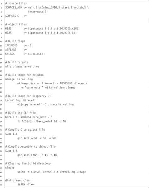
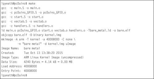
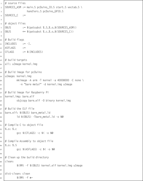
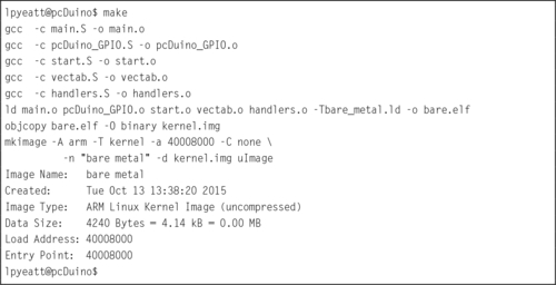
Compiling a program that consists of multiple source files, a custom linker script, and special commands to create an executable image can become tedious. The make utility was created specifically to help in this situation. Listing 14.8 shows a make script that can be used to combine all of the elements of the program together and produce a uImage file for the pcDuino and a kernel.img file for the Raspberry Pi. Listing 14.9 shows how the program can be built by typing “make” at the command line.
14.5 Using an Interrupt
The main program shown in Listing 14.6 is extremely wasteful because it runs the CPU in a loop, repeatedly checking the status of the GPIO pins. It uses far more CPU time (and electrical power) than is necessary. In reality, the pins are unlikely to change state very often, and it is sufficient to check them a few times per second. It only takes a few nanoseconds to check the input pins and set the output pins so the CPU only needs to be running for a few nanoseconds at a time, a few times per second.
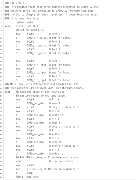
A much more efficient implementation would set up a timer to send interrupts at a fixed frequency. Then the main loop can check the buttons, set the outputs, and put the CPU to sleep. Listing 14.10 shows the main program, modified to put the processor to sleep after each iteration of the main loop. The only difference between this main function and the one in Listing 14.6 is the addition of a wfi instruction at line 43. The new implementation will consume far less electrical power and allow the CPU to run cooler, thereby extending its life. However, some additional work must be performed in order to set up the timer and interrupt system before the main function is called.
14.5.1 Startup Code
Some changes must be made to the startup code in Listing 14.5 so that after setting up the vector table, it calls a function to initialize the interrupt controller then calls another function to set up the timer. Listing 14.5 shows the modified startup function.
Lines 50 through 57 have been added to initialize the interrupt controller, enable the timer, and change the CPU into user mode before calling main. Of course, the hardware timers and interrupt controllers on the pcDuino and Raspberry Pi are very different.
14.5.2 Interrupt Controllers
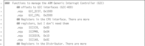
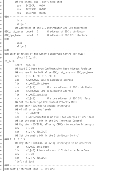
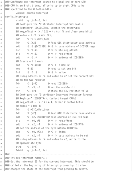
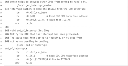
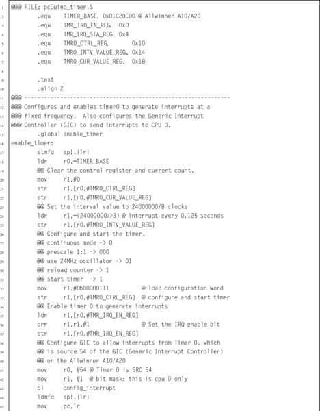
The pcDuino has an ARM Generic Interrupt Controller (GIC-400) device to manage interrupts. The GIC device can handle a large number of interrupts. Each one is a separate input signal to the GIC. The GIC hardware prioritizes each input, and assigns each one a unique integer identifier. When the CPU receives an interrupt, it simply reads the GIC to determine which hardware device signaled the interrupt, calls the function which handles that device, then writes to one of the GIC registers to indicate that the interrupt has been processed. Listing 14.12 provides a few basic functions for managing this device.
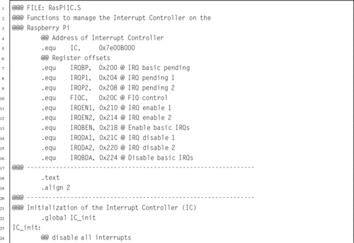
The Raspberry Pi has a much simpler interrupt controller. It can enable and disable interrupt sources, and requires that the programmer read up to three registers to determine the source of an interrupt. For our purposes, we only need to manage the ARM timer interrupt. Listing 14.13 provides a few basic functions for using this device to enable the timer interrupt. Extending these functions to provide functionality equal to the GIC would not be very difficult, but would take some time. It would be necessary to set up a mapping from the interrupt bits in the interrupt register controller to integer values, so that each interrupt source has a unique identifier. Then the functions could be written to use those identifiers. The result would be a software implementation to provide capabilities equivalent to the GIC.
Note that although the devices are very different internally, they perform basically the same function. With the addition of a software driver layer, implemented in Listings 14.12 and 14.13 the devices become interchangeable and other parts of the bare-metal program do not have to be changed when porting from one platform to the other.
14.5.3 Timers
The pcDuino provides several timers that could be used, Timer0 was chosen arbitrarily. Listing 14.14 provides a few basic functions for managing this Device.
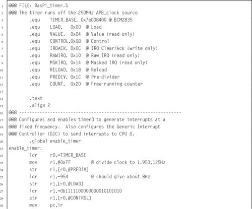
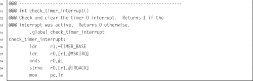
The Raspberry Pi also provides several timers that could be used, but the ARM timer is the easiest to configure. Listing 14.15 provides a few basic functions for managing this device:
14.5.4 Exception Handling
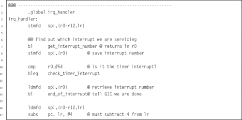
The final step in writing the bare-metal code to operate in an interrupt-driven fashion is to modify the IRQ handler from Listing 14.3. Listing 14.16 shows a new version of the IRQ exception handler which checks and clears the timer interrupt, then returns to the location and CPU mode that were current when the interrupt occurred. This code works for both platforms.
14.5.5 Building the Interrupt-Driven Program
Finally, the make file must be modified to include the new source code that was added to the program. Listing 14.17 shows the modified make script. The only change is that two extra object files have been added. when make is run, those files will be compiled and linked with the program. Listing 14.9 shows how the program can be built by typing “make” at the command line.
14.6 ARM Processor Profiles
Since its introduction in 1982 as the flagship processor for Acorn RISC Machine, the ARM processor has gone through many changes. Throughout the years, ARM processors have always maintained a good balance of simplicity, performance, and efficiency. Although originally intended as a desktop processor, the ARM architecture has been more successful than any other architecture for use in embedded applications. That is at least partially because of good choices made by its original designers. The architectural decisions resulted in a processor that provides relatively high computing power with a relatively small number of transistors. This design also results in relatively low power consumption.
Today, there are almost 20 major versions of the ARMv7 architecture, targeted for everything from smart sensors to desktops and servers, and sales of ARM-based processors outnumber all other processor architectures combined. Historically, ARM has given numbers to various versions of the architecture. With the ARMv7, they introduced a simpler scheme to describe different versions of the processor. They divided their processor families into three major profiles:
ARMv7-A: Applications processors are capable of running a full, multiuser, virtual memory, multiprocessing operating system.
ARMv7-R: Real-time processors are for embedded systems that may need powerful processors, cache, and/or large amounts of memory.
ARMv7-M: Microcontroller processors only execute Thumb instructions and are intended for use in very small cost-sensitive embedded systems. They provide low cost, low power, and small size, and may not have hardware floating point or other high-performance features.
In 2014, ARM introduced the ARMv8 architecture. This is the first radical change in the ARM architecture in over 30 years. The new architecture extends the register set to thirty 64-bit general purpose registers, and has a completely new instruction set. Compatibility with ARMv7 and earlier code is supported by switching the processor into 32-bit mode, so that it
executes the 32-bit ARM instruction set. This is somewhat similar to the way that the Thumb instructions are supported on 32-bit ARM cores, but the change to 32-bit code can only be made when the processor is in privileged mode, and drops back to unprivileged mode.
14.7 Chapter Summary
Writing bare-metal programs can be a daunting task. However, that task can be made easier by writing and testing code under an operating system before attempting to run it bare metal. There are some functions which cannot be tested in this way. In those cases, it is best to keep those functions as simple as possible. Once the program works on bare metal, extra capabilities can be added.
Interrupt-driven processing is the basis for all modern operating systems. The system timer allows the O/S to take control periodically and select a different process to run on the CPU. Interrupts allow hardware devices to do their jobs independently and signal the CPU when they need service. The ability to restrict user access to devices and certain processor features provides the basis for a secure and robust system.
Exercises
14.1 What are the advantages of a CPU which supports user mode and privileged mode over a CPU which does not?
14.2 What are the six privileged modes supported by the ARM architecture?
14.3 The interrupt handling mechanism is somewhat complex and requires significant programming effort to use. Why is it preferred over simply having the processor poll I/O devices?
14.4 Where does program control transfer to when a hardware interrupt occurs?
14.5 What is the purpose of the Undefined Instruction exception? How can it be used to allow an older processor to run programs that have new instructions? What other uses does it have?
14.6 What is an swi instruction? What is its use in operating systems? What is the key difference between an swi instruction and an interrupt?
14.7 Which of the following operations should be allowed only in privileged mode? Briefly explain your decision for each one.
(a) Execute an swi instruction.
(b) Disable all interrupts.
(c) Read the time-of-day clock.
(d) Receive a packet of data from the network.
(e) Shutdown the computer.
14.8 The main program in Listing 14.10 has two different methods to put the processor to sleep waiting for an interrupt. One method is for the Raspberry Pi, while the other is for the pcDuino. In order to compile the code, the correct lines must be uncommented and the unneeded lines must be commented out or removed. Explain two ways to change the code so that exactly the same main program can be used on both systems.
14.9 The programs in this chapter assumed the existence of libraries of functions for controlling the GPIO pins on the Raspberry Pi and the pcDuino. Both libraries provide the same high-level functions, but one operates on the Raspberry Pi GPIO device and the other operates on the pcDuino GPIO device. The C prototypes for the functions are: int GPIO_get_pin(int pin), void GPIO_set_pin(int pin,int state), GPIO_dir_input (int pin), and GPIO_dir_output (int pin). Write these libraries in ARM assembly language for both platforms.
14.10 Write an interrupt-driven program to read characters from the serial port on either the Raspberry Pi or the pcDuino. The UART on either system can be configured to send an interrupt when a character is received.
When a character is received through the UART and an interrupt occurs, the character should be echoed by transmitting it back to the sender. The character should also be stored in a buffer. If the character received is newline (“n), or if the buffer becomes full, then the contents of the buffer should be transmitted through the UART. Then, the buffer cleared and prepared to receive more characters.