Table of Contents for
Modern Assembly Language Programming with the ARM Processor
 Modern Assembly Language Programming with the ARM Processor
Published by
Newnes, 2016
Modern Assembly Language Programming with the ARM Processor
Published by
Newnes, 2016
- Modern Assembly Language Programming with the ARM Processor
- Cover image
- Title page
- Table of Contents
- Copyright
- List of Tables
- List of Figures
- List of Listings
- Preface
- Companion Website
- Acknowledgments
- Part I: Assembly as a Language
- Chapter 1: Introduction
- Chapter 2: GNU Assembly Syntax
- Chapter 3: Load/Store and Branch Instructions
- Chapter 4: Data Processing and Other Instructions
- Chapter 5: Structured Programming
- Chapter 6: Abstract Data Types
- Part II: Performance Mathematics
- Chapter 7: Integer Mathematics
- Chapter 8: Non-Integral Mathematics
- Chapter 9: The ARM Vector Floating Point Coprocessor
- Chapter 10: The ARM NEON Extensions
- 10.10 Multiplication and Division
- Part III: Accessing Devices
- Chapter 11: Devices
- Chapter 12: Pulse Modulation
- Chapter 13: Common System Devices
- Chapter 14: Running Without an Operating System
- Index
Introduction
Abstract
This chapter first gives a very high-level description of the major components of function of a computer system. It then motivates the reader by giving reasons why learning assembly language is important for Computer Scientists and Computer Engineers. It then explains why the ARM processor is a good choice for a first assembly language. Next it explains binary data representations, including various integer formats, ASCII, and Unicode. Finally, it describes the memory sections for a typical program during execution. By the end of the chapter, the groundwork has been laid for learning to program in assembly language.
Keywords
Instruction; Instruction stream; Central processing unit; Memory; Input/output device; High-level language; Assembly language; ARM processor; Binary; Hexadecimal; Decimal; Radix or base system; Base conversion; Sign magnitude; Unsigned; Complement; Excess-n; ASCII; Unicode; UTF-8; Stack; Heap; Data section; Text section
An executable computer program is, ultimately, just a series of numbers that have very little or no meaning to a human being. We have developed a variety of human-friendly languages in which to express computer programs, but in order for the program to execute, it must eventually be reduced to a stream of numbers. Assembly language is one step above writing the stream of numbers. The stream of numbers is called the instruction stream. Each number in the instruction stream instructs the computer to perform one (usually small) operation. Although each instruction does very little, the ability of the programmer to specify any sequence of instructions and the ability of the computer to perform billions of these small operations every second makes modern computers very powerful and flexible tools. In assembly language, one line of code usually gets translated into one machine instruction. In high-level languages, a single line of code may generate many machine instructions.
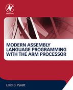
A simplified model of a computer system, as shown in Fig. 1.1, consists of memory, input/output devices, and a central processing unit (CPU), connected together by a system bus. The bus can be thought of as a roadway that allows data to travel between the components of the computer system. The CPU is the part of the system where most of the computation occurs, and the CPU controls the other devices in the system.
Memory can be thought of as a series of mailboxes. Each mailbox can hold a single postcard with a number written on it, and each mailbox has a unique numeric identifier. The identifier, x is called the memory address, and the number stored in the mailbox is called the contents of address x. Some of the mailboxes contain data, and others contain instructions which control what actions are performed by the CPU.
The CPU also contains a much smaller set of mailboxes, which we call registers. Data can be copied from cards stored in memory to cards stored in the CPU, or vice-versa. Once data has been copied into one of the CPU registers, it can be used in computation. For example, in order to add two numbers in memory, they must first be copied into registers on the CPU. The CPU can then add the numbers together and store the result in one of the CPU registers. The result of the addition can then be copied back into one of the mailboxes in the memory.
Modern computers execute instructions sequentially. In other words, the next instruction to be executed is at the memory address immediately following the current instruction. One of the registers in the CPU, the program counter (PC), keeps track of the location from which the next instruction is to be fetched. The CPU follows a very simple sequence of actions. It fetches an instruction from memory, increments the PC, executes the instruction, and then repeats the process with the next instruction. However, some instructions may change the PC, so that the next instruction is fetched from a non-sequential address.
1.1 Reasons to Learn Assembly
There are many high-level programming languages, such as Java, Python, C, and C++ that have been designed to allow programmers to work at a high level of abstraction, so that they do not need to understand exactly what instructions are needed by a particular CPU. For compiled languages, such as C and C++, a compiler handles the task of translating the program, written in a high-level language, into assembly language for the particular CPU on the system. An assembler then converts the program from assembly language into the binary codes that the CPU reads as instructions.
High-level languages can greatly enhance programmer productivity. However, there are some situations where writing assembly code directly is desirable or necessary. For example, assembly language may be the best choice when writing
• the first steps in booting the computer,
• code to handle interrupts,
• low-level locking code for multi-threaded programs,
• code for machines where no compiler exists,
• code which needs to be optimized beyond the limits of the compiler,
• on computers with very limited memory, and
• code that requires low-level access to architectural and/or processor features.
Aside from sheer necessity, there are several other reasons why it is still important for computer scientists to learn assembly language.
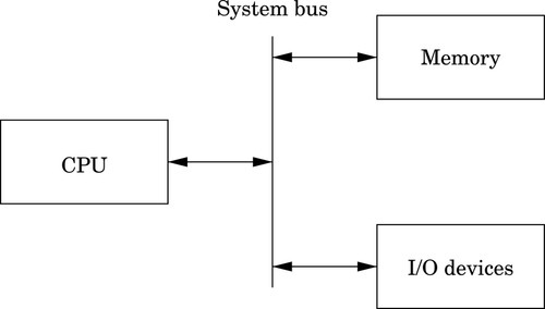
One example where knowledge of assembly is indispensable is when designing and implementing compilers for high-level languages. As shown in Fig. 1.2, a typical compiler for a high-level language must generate assembly language as its output. Most compilers are designed to have multiple stages. In the input stage, the source language is read and converted into a graph representation. The graph may be optimized before being passed to the output, or code generation, stage where it is converted to assembly language. The assembly is then fed into the system’s assembler to generate an object file. The object file is linked with other object files (which are often combined into libraries) to create an executable program.
The code generation stage of a compiler must traverse the graph and emit assembly code. The quality of the assembly code that is generated can have a profound influence on the performance of the executable program. Therefore, the programmer responsible for the code generation portion of the compiler must be well versed in assembly programming for the target CPU.
Some people believe that a good optimizing compiler will generate better assembly code than a human programmer. This belief is not justified. Highly optimizing compilers have lots of clever algorithms, but like all programs, they are not perfect. Outside of the cases that they were designed for, they do not optimize well. Many newer CPUs have instructions which operate on multiple items of data at once. However, compilers rarely make use of these powerful single instruction multiple data ( SIMD) instructions. Instead, it is common for programmers to write functions in assembly language to take advantage of SIMD instructions. The assembly functions are assembled into object file(s), then linked with the object file(s) generated from the high-level language compiler.
Many modern processors also have some support for processing vectors (arrays). Compilers are usually not very good at making effective use of the vector instructions. In order to achieve excellent vector performance for audio or video codecs and other time-critical code, it is often necessary to resort to small pieces of assembly code in the performance-critical inner loops. A good example of this type of code is when performing vector and matrix multiplies. Such operations are commonly needed in processing images and in graphical applications. The ARM vector instructions are explained in Chapter 9.
Another reason for assembly is when writing certain parts of an operating system. Although modern operating systems are mostly written in high-level languages, there are some portions of the code that can only be done in assembly. Typical uses of assembly language are when writing device drivers, saving the state of a running program so that another program can use the CPU, restoring the saved state of a running program so that it can resume executing, and managing memory and memory protection hardware. There are many other tasks central to a modern operating system which can only be accomplished in assembly language. Careful design of the operating system can minimize the amount of assembly required, but cannot eliminate it completely.
Another good reason to learn assembly is for debugging. Simply understanding what is going on “behind the scenes” of compiled languages such as C and C++ can be very valuable when trying to debug programs. If there is a problem in a call to a third party library, sometimes the only way a developer can isolate and diagnose the problem is to run the program under a debugger and step through it one machine instruction at a time. This does not require a deep knowledge of assembly language coding but at least a passing familiarity with assembly is helpful in that particular case. Analysis of assembly code is an important skill for C and C++ programmers, who may occasionally have to diagnose a fault by looking at the contents of CPU registers and single-stepping through machine instructions.
Assembly language is an important part of the path to understanding how the machine works. Even though only a small percentage of computer scientists will be lucky enough to work on the code generator of a compiler, they all can benefit from the deeper level of understanding gained by learning assembly language. Many programmers do not really understand pointers until they have written assembly language.
Without first learning assembly language, it is impossible to learn advanced concepts such as microcode, pipelining, instruction scheduling, out-of-order execution, threading, branch prediction, and speculative execution. There are many other concepts, especially when dealing with operating systems and computer architecture, which require some understanding of assembly language. The best programmers understand why some language constructs perform better than others, how to reduce cache misses, and how to prevent buffer overruns that destroy security.
Every program is meant to run on a real machine. Even though there are many languages, compilers, virtual machines, and operating systems to enable the programmer to use the machine more conveniently, the strengths and weaknesses of that machine still determine what is easy and what is hard. Learning assembly is a fundamental part of understanding enough about the machine to make informed choices about how to write efficient programs, even when writing in a high-level language.
As an analogy, most people do not need to know a lot about how an internal combustion engine works in order to operate an automobile. A race car driver needs a much better understanding of exactly what happens when he or she steps on the accelerator pedal in order to be able to judge precisely when (and how hard) to do so. Also, who would trust their car to a mechanic who could not tell the difference between a spark plug and a brake caliper? Worse still, should we trust an engineer to build a car without that knowledge? Even in this day of computerized cars, someone needs to know the gritty details, and they are paid well for that knowledge. Knowledge of assembly language is one of the things that defines the computer scientist and engineer.
When learning assembly language, the specific instruction set is not critically important, because what is really being learned is the fine detail of how a typical stored-program machine uses different storage locations and logic operations to convert a string of bits into a meaningful calculation. However, when it comes to learning assembly languages, some processors make it more difficult than it needs to be. Because some processors have an instruction set that is extremely irregular, non-orthogonal, large, and poorly designed, they are not a good choice for learning assembly. The author feels that teaching students their first assembly language on one of those processors should be considered a crime, or at least a form of mental abuse. Luckily, there are processors that are readily available, low-cost, and relatively easy to learn assembly with. This book uses one of them as the model for assembly language.
1.2 The ARM Processor
In the late 1970s, the microcomputer industry was a fierce battleground, with several companies competing to sell computers to small business and home users. One of those companies, based in the United Kingdom, was Acorn Computers Ltd. Acorn’s flagship product, the BBC Micro, was based on the same processor that Apple Computer had chosen for their Apple IITM line of computers; the 8-bit 6502 made by MOS Technology. As the 1980s approached, microcomputer manufacturers were looking for more powerful 16-bit and 32-bit processors. The engineers at Acorn considered the processor chips that were available at the time, and concluded that there was nothing available that would meet their needs for the next generation of Acorn computers.
The only reasonably-priced processors that were available were the Motorola 68000 (a 32-bit processor used in the Apple Macintosh and most high-end Unix workstations) and the Intel 80286 (a 16-bit processor used in less powerful personal computers such as the IBM PC). During the previous decade, a great deal of research had been conducted on developing high-performance computer architectures. One of the outcomes of that research was the development of a new paradigm for processor design, known as Reduced Instruction Set Computing (RISC). One advantage of RISC processors was that they could deliver higher performance with a much smaller number of transistors than the older Complex Instruction Set Computing (CISC) processors such as the 68000 and 80286. The engineers at Acorn decided to design and produce their own processor. They used the BBC Micro to design and simulate their new processor, and in 1987, they introduced the Acorn ArchimedesTM. The ArchimedesTM was arguably the most powerful home computer in the world at that time, with graphics and audio capabilities that IBM PCTM and Apple MacintoshTM users could only dream about. Thus began the long and successful dynasty of the Acorn RISC Machine (ARM) processor.
Acorn never made a big impact on the global computer market. Although Acorn eventually went out of business, the processor that they created has lived on. It was re-named to the Advanced RISC Machine, and is now known simply as ARM. Stewardship of the ARM processor belongs to ARM Holdings, LLC which manages the design of new ARM architectures and licenses the manufacturing rights to other companies. ARM Holdings does not manufacture any processor chips, yet more ARM processors are produced annually than all other processor designs combined. Most ARM processors are used as components for embedded systems and portable devices. If you have a smart phone or similar device, then there is a very good chance that it has an ARM processor in it. Because of its enormous market presence, clean architecture, and small, orthogonal instruction set, the ARM is a very good choice for learning assembly language.
Although it dominates the portable device market, the ARM processor has almost no presence in the desktop or server market. However, that may change. In 2012, ARM Holdings announced the ARM64 architecture, which is the first major redesign of the ARM architecture in 30 years. The ARM64 is intended to compete for the desktop and server market with other high-end processors such as the Sun SPARC and Intel Xeon. Regardless of whether or not the ARM64 achieves much market penetration, the original ARM 32-bit processor architecture is so ubiquitous that it clearly will be around for a long time.
1.3 Computer Data
The basic unit of data in a digital computer is the binary digit, or bit. A bit can have a value of zero or one. In order to store numbers larger than 1, bits are combined into larger units. For instance, using two bits, it is possible to represent any number between zero and three. This is shown in Table 1.1. When stored in the computer, all data is simply a string of binary digits. There is more than one way that such a fixed-length string of binary digits can be interpreted.
Computers have been designed using many different bit group sizes, including 4, 8, 10, 12, and 14 bits. Today most computers recognize a basic grouping of 8 bits, which we call a byte. Some computers can work in units of 4 bits, which is commonly referred to as a nibble (sometimes spelled “nybble”). A nibble is a convenient size because it can exactly represent one hexadecimal digit. Additionally, most modern computers can also work with groupings of 16, 32 and 64 bits. The CPU is designed with a default word size. For most modern CPUs, the default word size is 32 bits. Many processors support 64-bit words, which is increasingly becoming the default size.
1.3.1 Representing Natural Numbers
A numeral system is a writing system for expressing numbers. The most common system is the Hindu-Arabic number system, which is now used throughout the world. Almost from the first day of formal education, children begin learning how to add, subtract, and perform other operations using the Hindu-Arabic system. After years of practice, performing basic mathematical operations using strings of digits between 0 and 9 seems natural. However, there are other ways to count and perform arithmetic, such as Roman numerals, unary systems, and Chinese numerals. With a little practice, it is possible to become as proficient at performing mathematics with other number systems as with the Hindu-Arabic system.
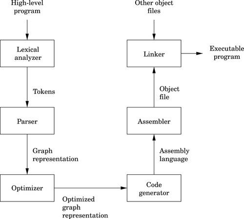
The Hindu-Arabic system is a base ten or radix ten system, because it uses the ten digits 0, 1, 2, 3, 4, 5, 6, 7, 8, and 9. For our purposes, the words radix and base are equivalent, and refer to the number of individual digits available in the numbering system. The Hindu-Arabic system is also a positional system, or a place-value notation, because the value of each digit in a number depends on its position in the number. The radix ten Hindu-Arabic system is only one of an infinite family of closely related positional systems. The members of this family differ only in the radix used (and therefore, the number of characters used). For bases greater than base ten, characters are borrowed from the alphabet and used to represent digits. For example, the first column in Table 1.2 shows the character “A” being used as a single digit representation for the number 10.
Table 1.2
The first 21 integers (starting with 0) in various bases
| Base | |||||||||
| 16 | 10 | 9 | 8 | 7 | 6 | 5 | 4 | 3 | 2 |
| 0 | 0 | 0 | 0 | 0 | 0 | 0 | 0 | 0 | 0 |
| 1 | 1 | 1 | 1 | 1 | 1 | 1 | 1 | 1 | 1 |
| 2 | 2 | 2 | 2 | 2 | 2 | 2 | 2 | 2 | 10 |
| 3 | 3 | 3 | 3 | 3 | 3 | 3 | 3 | 10 | 11 |
| 4 | 4 | 4 | 4 | 4 | 4 | 4 | 10 | 11 | 100 |
| 5 | 5 | 5 | 5 | 5 | 5 | 10 | 11 | 12 | 101 |
| 6 | 6 | 6 | 6 | 6 | 10 | 11 | 12 | 20 | 110 |
| 7 | 7 | 7 | 7 | 10 | 11 | 12 | 13 | 21 | 111 |
| 8 | 8 | 8 | 10 | 11 | 12 | 13 | 20 | 22 | 1000 |
| 9 | 9 | 10 | 11 | 12 | 13 | 14 | 21 | 100 | 1001 |
| A | 10 | 11 | 12 | 13 | 14 | 20 | 22 | 101 | 1010 |
| B | 11 | 12 | 13 | 14 | 15 | 21 | 23 | 102 | 1011 |
| C | 12 | 13 | 14 | 15 | 20 | 22 | 30 | 110 | 1100 |
| D | 13 | 14 | 15 | 16 | 21 | 23 | 31 | 111 | 1101 |
| E | 14 | 15 | 16 | 20 | 22 | 24 | 32 | 112 | 1110 |
| F | 15 | 16 | 17 | 21 | 23 | 30 | 33 | 120 | 1111 |
| 10 | 16 | 17 | 20 | 22 | 24 | 31 | 100 | 121 | 10000 |
| 11 | 17 | 18 | 21 | 23 | 25 | 32 | 101 | 122 | 10001 |
| 12 | 18 | 20 | 22 | 24 | 30 | 33 | 102 | 200 | 10010 |
| 13 | 19 | 21 | 23 | 25 | 31 | 34 | 103 | 201 | 10011 |
| 14 | 20 | 22 | 24 | 26 | 32 | 40 | 110 | 201 | 10100 |
In base ten, we think of numbers as strings of the 10 digits, “0”–“9”. Each digit counts 10 times the amount of the digit to its right. If we restrict ourselves to integers, then the digit furthest to the right is always the ones digit. It is also referred to as the least significant digit. The digit immediately to the left of the ones digit is the tens digit. To the left of that is the hundreds digit, and so on. The leftmost digit is referred to as the most significant digit. The following equation shows how a number can be decomposed into its constituent digits:

Note that the subscript of “10” on 5783910 indicates that the number is given in base ten.
Imagine that we only had 7 digits: 0, 1, 2, 3, 4, 5, and 6. We need 10 digits for base ten, so with only 7 digits we are limited to base seven. In base seven, each digit in the string represents a power of seven rather than a power of ten. We can represent any integer in base seven, but it may take more digits than in base ten. Other than using a different base for the power of each digit, the math works exactly the same as for base ten. For example, suppose we have the following number in base seven: 3304257. We can convert this number to base ten as follows:
Base two, or binary is the “native” number system for modern digital systems. The reason for this is mainly because it is relatively easy to build circuits with two stable states: on and off (or 1 and 0). Building circuits with more than two stable states is much more difficult and expensive, and any computation that can be performed in a higher base can also be performed in binary. The least significant (rightmost) digit in binary is referred to as the least significant bit, or LSB, while the leftmost binary digit is referred to as the most significant bit, or MSB.
1.3.2 Base Conversion
The most common bases used by programmers are base two (binary), base eight (octal), base ten (decimal) and base sixteen (hexadecimal). Octal and hexadecimal are common because, as we shall see later, they can be translated quickly and easily to and from base two, and are often easier for humans to work with than base two. Note that for base sixteen, we need 16 characters. We use the digits 0 through 9 plus the letters A through F. Table 1.2 shows the equivalents for all numbers between 0 and 20 in base two through base ten, and base sixteen.
Before learning assembly language it is essential to know how to convert from any base to any other base. Since we are already comfortable working in base ten, we will use that as an intermediary when converting between two arbitrary bases. For instance, if we want to convert a number in base three to base five, we will do it by first converting the base three number to base ten, then from base ten to base five. By using this two-stage process, we will only need to learn to convert between base ten and any arbitrary base b.
Base b to decimal
Converting from an arbitrary base b to base ten simply involves multiplying each base b digit d by bn, where n is the significance of digit d, and summing all of the results. For example, converting the base five number 34215 to base ten is performed as follows:
This conversion procedure works for converting any integer from any arbitrary base b to its equivalent representation in base ten. Example 1.1 gives another specific example of how to convert from base b to base ten.
Decimal to base b
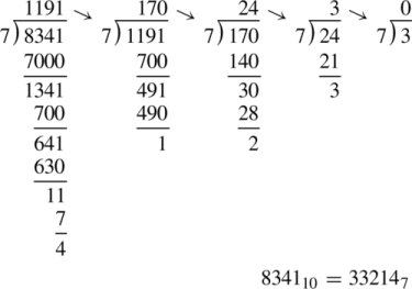
Converting from base ten to an arbitrary base b involves repeated division by the base, b. After each division, the remainder is used as the next more significant digit in the base b number, and the quotient is used as the dividend for the next iteration. The process is repeated until the quotient is zero. For example, converting 5610 to base four is accomplished as follows:
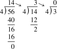
Reading the remainders from right to left yields: 3204. This result can be double-checked by converting it back to base ten as follows:
Since we arrived at the same number we started with, we have verified that 5610 = 3204. This conversion procedure works for converting any integer from base ten to any arbitrary base b. Example 1.2 gives another example of converting from base ten to another base b.
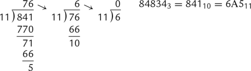
Conversion between arbitrary bases
Although it is possible to perform the division and multiplication steps in any base, most people are much better at working in base ten. For that reason, the easiest way to convert from any base a to any other base b is to use a two step process. First step is to convert from base a to decimal. The second step is to convert from decimal to base b. Example 1.3 shows how to convert from any base to any other base.
Bases that are powers-of-two
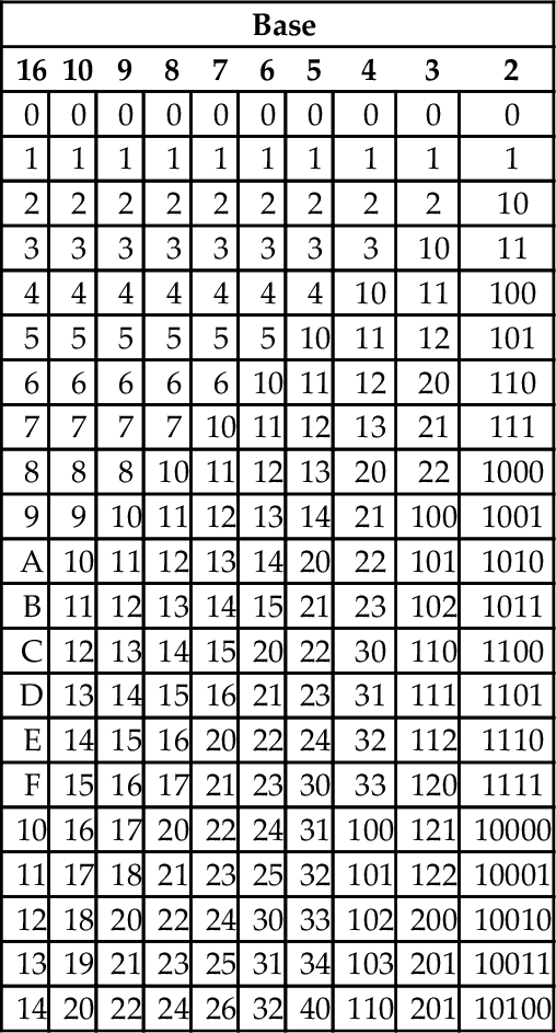
In addition to the methods above, there is a simple method for quickly converting between base two, base eight, and base sixteen. These shortcuts rely on the fact that 2, 8, and 16 are all powers of two. Because of this, it takes exactly four binary digits (bits) to represent exactly one hexadecimal digit. Likewise, it takes exactly three bits to represent an octal digit. Conversely, each hexadecimal digit can be converted to exactly four binary digits, and each octal digit can be converted to exactly three binary digits. This relationship makes it possible to do very fast conversions using the tables shown in Fig. 1.3.
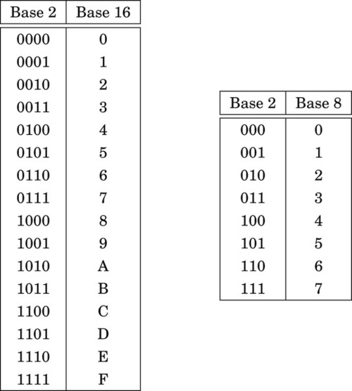
When converting from hexadecimal to binary, all that is necessary is to replace each hex digit with the corresponding binary digits from the table. For example, to convert 5AC416 to binary, we just replace “5” with “0101,” replace “A” with “1010,” replace “C” with “1100,” and replace “4” with “0100.” So, just by referring to the table, we can immediately see that 5AC416 = 01011010110001002. This method works exactly the same for converting from octal to binary, except that it uses the table on the right side of Fig. 1.3.
Converting from binary to hexadecimal is also very easy using the table. Given a binary number, n, take the four least significant digits of n and find them in the table on the left side of Fig. 1.3. The hexadecimal digit on the matching line of the table is the least significant hex digit. Repeat the process with the next set of four bits and continue until there are no bits remaining in the binary number. For example, to convert 00111001010101112 to hexadecimal, just divide the number into groups of four bits, starting on the right, to get: 0011|1001|0101|01112. Now replace each group of four bits by looking up the corresponding hex digit in the table on the left side of Fig. 1.3, to convert the binary number to 395716. In the case where the binary number does not have enough bits, simply pad with zeros in the high-order bits. For example, dividing the number 10011000100112 into groups of four yields 1|0011|0001|00112 and padding with zeros in the high-order bits results in 0001|0011|0001|00112. Looking up the four groups in the table reveals that 0001|0011|0001|00112 = 131316.
1.3.3 Representing Integers
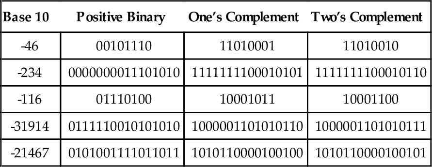
The computer stores groups of bits, but the bits by themselves have no meaning. The programmer gives them meaning by deciding what the bits represent, and how they are interpreted. Interpreting a group of bits as unsigned integer data is relatively simple. Each bit is weighted by a power-of-two, and the value of the group of bits is the sum of the non-zero bits multiplied by their respective weights. However, programmers often need to represent negative as well as non-negative numbers, and there are many possibilities for storing and interpreting integers whose value can be both positive and negative. Programmers and hardware designers have developed several standard schemes for encoding such numbers. The three main methods for storing and interpreting signed integer data are two’s complement, sign-magnitude, and excess-N, Fig. 1.4 shows how the same binary pattern of bits can be interpreted as a number in four different ways.
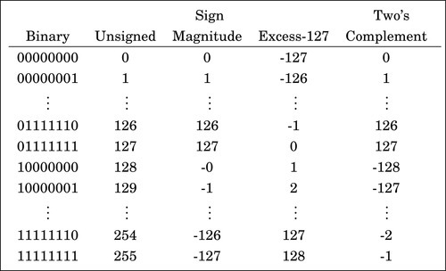
Sign-magnitude representation
The sign-magnitude representation simply reserves the most significant bit to represent the sign of the number, and the remaining bits are used to store the magnitude of the number. This method has the advantage that it is easy for humans to interpret, with a little practice. However, addition and subtraction are slightly complicated. The addition/subtraction logic must compare the sign bits, complement one of the inputs if they are different, implement an end-around carry, and complement the result if there was no carry from the most significant bit. Complements are explained in Section 1.3.3. Because of the complexity, most integer CPUs do not directly support addition and subtraction of integers in sign-magnitude form. However, this method is commonly used for mantissa in floating-point numbers, as will be explained in Chapter 8. Another drawback to sign-magnitude is that it has two representations for zero, which can cause problems if the programmer is not careful.
Excess-(2n−1 − 1) representation
Another method for representing both positive and negative numbers is by using an excess-N representation. With this representation, the number that is stored is N greater than the actual value. This representation is relatively easy for humans to interpret. Addition and subtraction are easily performed using the complement method, which is explained in Section 1.3.3. This representation is just the same as unsigned math, with the addition of a bias which is usually (2n−1 − 1). So, zero is represented as zero plus the bias. In n = 12 bits, the bias is 212−1 − 1 = 204710, or 0111111111112. This method is commonly used to store the exponent in floating-point numbers, as will be explained in Chapter 8.
Complement representation
A very efficient method for dealing with signed numbers involves representing negative numbers as the radix complements of their positive counterparts. The complement is the amount that must be added to something to make it “whole.” For instance, in geometry, two angles are complementary if they add to 90°. In radix mathematics, the complement of a digit x in base b is simply b − x. For example, in base ten, the complement of 4 is 10 − 4 = 6.
In complement representation, the most significant digit of a number is reserved to indicate whether or not the number is negative. If the first digit is less than  (where b is the radix), then the number is positive. If the first digit is greater than or equal to , then the number is negative. The first digit is not part of the magnitude of the number, but only indicates the sign of the number. For example, numbers in ten’s complement notation are positive if the first digit is less than 5, and negative if the first digit is greater than 4. This works especially well in binary, since the number is considered positive if the first bit is zero and negative if the first bit is one. The magnitude of a negative number can be obtained by taking the radix complement. Because of the nice properties of the complement representation, it is the most common method for representing signed numbers in digital computers.
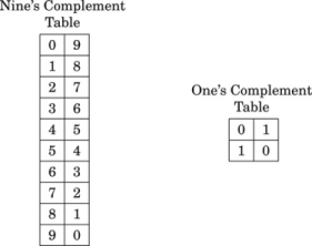
Finding the complement: The radix complement of an n digit number y in radix ( base) b is defined as

For example, the ten’s complement of the four digit number 873410 is 104 − 8734 = 1266. In this example, we directly applied the definition of the radix complement from Eq. (1.4). That is easy in base ten, but not so easy in an arbitrary base, because it involves performing a subtraction. However, there is a very simple method for calculating the complement which does not require subtraction. This method involves finding the diminished radix complement, which is (bn − 1) − y by substituting each digit with its complement from a complement table. The radix complement is found by adding one to the diminished radix complement. Fig. 1.5 shows the complement tables for bases ten and two. Examples 1.4 and 1.5 show how the complement is obtained in bases ten and two respectively. Examples 1.6 and 1.7 show additional conversions between binary and decimal.
Example 1.6
Conversion from Binary to Decimal
Suppose we want to convert a signed binary number to decimal.
1. If the most significant bit is ‘1’, then
a. Find the two’s complement
b. Convert the result to base 10
c. Add a negative sign
2. else
a. Convert the result to base 10
Example 1.7
Conversion from Decimal to Binary
Suppose we want to convert a negative number from decimal to binary.
1. Remove the negative sign
2. Convert the number to binary
3. Take the two’s complement
Subtraction using complements One very useful feature of complement notation is that it can be used to perform subtraction by using addition. Given two numbers in base b, xb, and yb, the difference can be computed as:


where C(yb) is the radix complement of yb. Assume that xb and yb are both positive where yb ≤ xb and both numbers have the same number of digits n (yb may have leading zeros). In this case, the result of xb + C(yb) will always be greater than or equal to bn, but less than 2 × bn. This means that the result of xb + C(yb) will always begin with a ‘1’ in the n + 1 digit position. Dropping the initial ‘1’ is equivalent to subtracting bn, making the result x − y + bn − bn or just x − y, which is the desired result. This can be reduced to a simple procedure. When y and x are both positive and y ≤ x, the following four steps are to be performed:
1. pad the subtrahend (y) with leading zeros, as necessary, so that both numbers have the same number of digits (n),
2. find the b’s complement of the subtrahend,
3. add the complement to the minuend,
4. discard the leading ‘1’.
The complement notation provides a very easy way to represent both positive and negative integers using a fixed number of digits, and to perform subtraction by using addition. Since modern computers typically use a fixed number of bits, complement notation provides a very convenient and efficient way to store signed integers and perform mathematical operations on them. Hardware is simplified because there is no need to build a specialized subtractor circuit. Instead, a very simple complement circuit is built and the adder is reused to perform subtraction as well as addition.
1.3.4 Representing Characters
In the previous section, we discussed how the computer stores information as groups of bits, and how we can interpret those bits as numbers in base two. Given that the computer can only store information using groups of bits, how can we store textual information? The answer is that we create a table, which assigns a numerical value to each character in our language.
Early in the development of computers, several computer manufacturers developed such tables, or character coding schemes. These schemes were incompatible and computers from different manufacturers could not easily exchange textual data without the use of translation software to convert the character codes from one coding scheme to another.
Eventually, a standard coding scheme, known as the American Standard Code for Information Interchange (ASCII) was developed. Work on the ASCII standard began on October 6, 1960, with the first meeting of the American Standards Association’s (ASA) X3.2 subcommittee. The first edition of the standard was published in 1963. The standard was updated in 1967 and again in 1986, and has been stable since then. Within a few years of its development, ASCII was accepted by all major computer manufacturers, although some continue to support their own coding schemes as well.
ASCII was designed for American English, and does not support some of the characters that are used by non-English languages. For this reason, ASCII has been extended to create more comprehensive coding schemes. Most modern multilingual coding schemes are based on ASCII, though they support a wider range of characters.
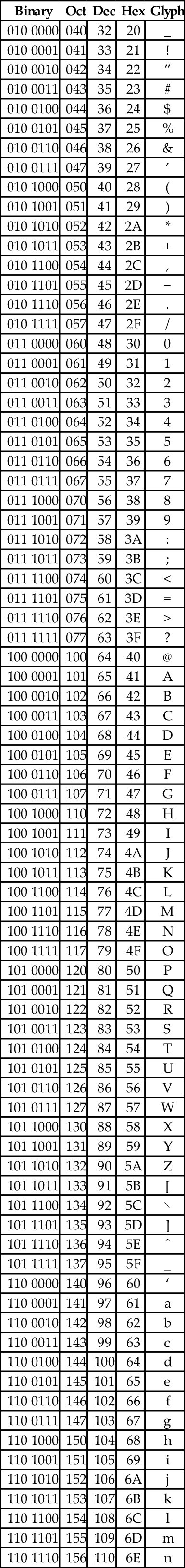
At the time that it was developed, transmission of digital data over long distances was very slow, and usually involved converting each bit into an audio signal which was transmitted over a telephone line using an acoustic modem. In order to maximize performance, the standards committee chose to define ASCII as a 7-bit code. Because of this decision, all textual data could be sent using seven bits rather than eight, resulting in approximately 10% better overall performance when transmitting data over a telephone modem. A possibly unforeseen benefit was that this also provided a way for the code to be extended in the future. Since there are 128 possible values for a 7-bit number, the ASCII standard provides 128 characters. However, 33 of the ASCII characters are non-printing control characters. These characters, shown in Table 1.3, are mainly used to send information about how the text is to be displayed and/or printed. The remaining 95 printable characters are shown in Table 1.4.
Table 1.3
The ASCII control characters
| Binary | Oct | Dec | Hex | Abbr | Glyph | Name |
| 000 0000 | 000 | 0 | 00 | NUL | ˆ@ | Null character |
| 000 0001 | 001 | 1 | 01 | SOH | ˆA | Start of header |
| 000 0010 | 002 | 2 | 02 | STX | ˆB | Start of text |
| 000 0011 | 003 | 3 | 03 | ETX | ˆC | End of text |
| 000 0100 | 004 | 4 | 04 | EOT | ˆD | End of transmission |
| 000 0101 | 005 | 5 | 05 | ENQ | ˆE | Enquiry |
| 000 0110 | 006 | 6 | 06 | ACK | ˆF | Acknowledgment |
| 000 0111 | 007 | 7 | 07 | BEL | ˆG | Bell |
| 000 1000 | 010 | 8 | 08 | BS | ˆH | Backspace |
| 000 1001 | 011 | 9 | 09 | HT | ˆI | Horizontal tab |
| 000 1010 | 012 | 10 | 0A | LF | ˆJ | Line feed |
| 000 1011 | 013 | 11 | 0B | VT | ˆK | Vertical tab |
| 000 1100 | 014 | 12 | 0C | FF | ˆL | Form feed |
| 000 1101 | 015 | 13 | 0D | CR | ˆM | Carriage return[g] |
| 000 1110 | 016 | 14 | 0E | SO | ˆN | Shift out |
| 000 1111 | 017 | 15 | 0F | SI | ˆO | Shift in |
| 001 0000 | 020 | 16 | 10 | DLE | ˆP | Data link escape |
| 001 0001 | 021 | 17 | 11 | DC1 | ˆQ | Device control 1 (oft. XON) |
| 001 0010 | 022 | 18 | 12 | DC2 | ˆR | Device control 2 |
| 001 0011 | 023 | 19 | 13 | DC3 | ˆS | Device control 3 (oft. XOFF) |
| 001 0100 | 024 | 20 | 14 | DC4 | ˆT | Device control 4 |
| 001 0101 | 025 | 21 | 15 | NAK | ˆU | Negative acknowledgement |
| 001 0110 | 026 | 22 | 16 | SYN | ˆV | Synchronous idle |
| 001 0111 | 027 | 23 | 17 | ETB | ˆW | End of transmission Block |
| 001 1000 | 030 | 24 | 18 | CAN | ˆX | Cancel |
| 001 1001 | 031 | 25 | 19 | EM | ˆY | End of medium |
| 001 1010 | 032 | 26 | 1A | SUB | ˆZ | Substitute |
| 001 1011 | 033 | 27 | 1B | ESC | ˆ[ | Escape |
| 001 1100 | 034 | 28 | 1C | FS | ˆ\ | File separator |
| 001 1101 | 035 | 29 | 1D | GS | ˆ] | Group separator |
| 001 1110 | 036 | 30 | 1E | RS | ˆˆ | Record separator |
| 001 1111 | 037 | 31 | 1F | US | ˆ_ | Unit separator |
| 111 1111 | 177 | 127 | 7F | DEL | ˆ? | Delete |
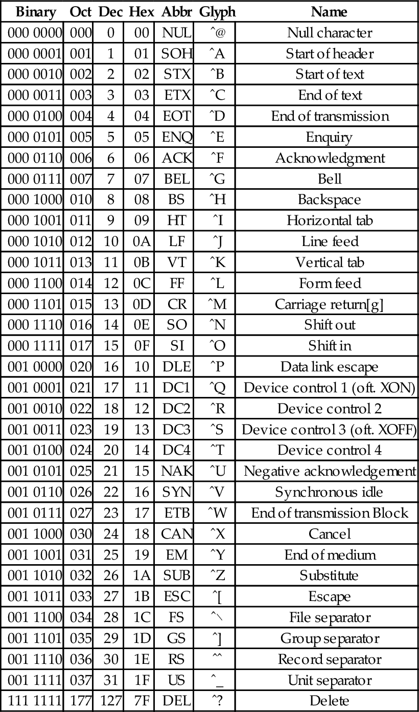
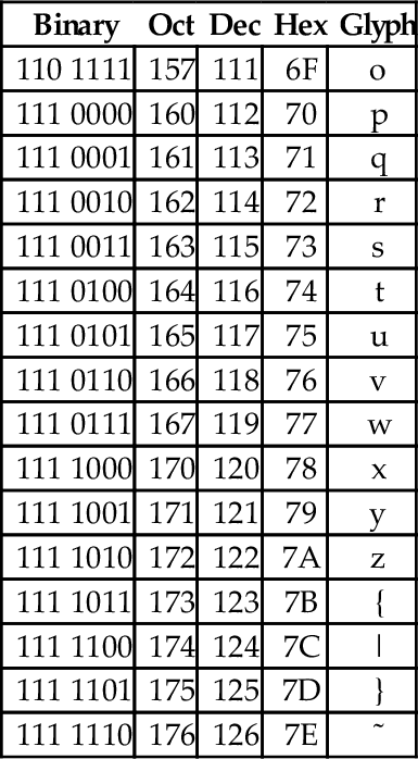
Table 1.4
The ASCII printable characters
| Binary | Oct | Dec | Hex | Glyph |
| 010 0000 | 040 | 32 | 20 | _ |
| 010 0001 | 041 | 33 | 21 | ! |
| 010 0010 | 042 | 34 | 22 | ” |
| 010 0011 | 043 | 35 | 23 | # |
| 010 0100 | 044 | 36 | 24 | $ |
| 010 0101 | 045 | 37 | 25 | % |
| 010 0110 | 046 | 38 | 26 | & |
| 010 0111 | 047 | 39 | 27 | ’ |
| 010 1000 | 050 | 40 | 28 | ( |
| 010 1001 | 051 | 41 | 29 | ) |
| 010 1010 | 052 | 42 | 2A | * |
| 010 1011 | 053 | 43 | 2B | + |
| 010 1100 | 054 | 44 | 2C | , |
| 010 1101 | 055 | 45 | 2D | − |
| 010 1110 | 056 | 46 | 2E | . |
| 010 1111 | 057 | 47 | 2F | / |
| 011 0000 | 060 | 48 | 30 | 0 |
| 011 0001 | 061 | 49 | 31 | 1 |
| 011 0010 | 062 | 50 | 32 | 2 |
| 011 0011 | 063 | 51 | 33 | 3 |
| 011 0100 | 064 | 52 | 34 | 4 |
| 011 0101 | 065 | 53 | 35 | 5 |
| 011 0110 | 066 | 54 | 36 | 6 |
| 011 0111 | 067 | 55 | 37 | 7 |
| 011 1000 | 070 | 56 | 38 | 8 |
| 011 1001 | 071 | 57 | 39 | 9 |
| 011 1010 | 072 | 58 | 3A | : |
| 011 1011 | 073 | 59 | 3B | ; |
| 011 1100 | 074 | 60 | 3C | < |
| 011 1101 | 075 | 61 | 3D | = |
| 011 1110 | 076 | 62 | 3E | > |
| 011 1111 | 077 | 63 | 3F | ? |
| 100 0000 | 100 | 64 | 40 | @ |
| 100 0001 | 101 | 65 | 41 | A |
| 100 0010 | 102 | 66 | 42 | B |
| 100 0011 | 103 | 67 | 43 | C |
| 100 0100 | 104 | 68 | 44 | D |
| 100 0101 | 105 | 69 | 45 | E |
| 100 0110 | 106 | 70 | 46 | F |
| 100 0111 | 107 | 71 | 47 | G |
| 100 1000 | 110 | 72 | 48 | H |
| 100 1001 | 111 | 73 | 49 | I |
| 100 1010 | 112 | 74 | 4A | J |
| 100 1011 | 113 | 75 | 4B | K |
| 100 1100 | 114 | 76 | 4C | L |
| 100 1101 | 115 | 77 | 4D | M |
| 100 1110 | 116 | 78 | 4E | N |
| 100 1111 | 117 | 79 | 4F | O |
| 101 0000 | 120 | 80 | 50 | P |
| 101 0001 | 121 | 81 | 51 | Q |
| 101 0010 | 122 | 82 | 52 | R |
| 101 0011 | 123 | 83 | 53 | S |
| 101 0100 | 124 | 84 | 54 | T |
| 101 0101 | 125 | 85 | 55 | U |
| 101 0110 | 126 | 86 | 56 | V |
| 101 0111 | 127 | 87 | 57 | W |
| 101 1000 | 130 | 88 | 58 | X |
| 101 1001 | 131 | 89 | 59 | Y |
| 101 1010 | 132 | 90 | 5A | Z |
| 101 1011 | 133 | 91 | 5B | [ |
| 101 1100 | 134 | 92 | 5C | \ |
| 101 1101 | 135 | 93 | 5D | ] |
| 101 1110 | 136 | 94 | 5E | ˆ |
| 101 1111 | 137 | 95 | 5F | _ |
| 110 0000 | 140 | 96 | 60 | ‘ |
| 110 0001 | 141 | 97 | 61 | a |
| 110 0010 | 142 | 98 | 62 | b |
| 110 0011 | 143 | 99 | 63 | c |
| 110 0100 | 144 | 100 | 64 | d |
| 110 0101 | 145 | 101 | 65 | e |
| 110 0110 | 146 | 102 | 66 | f |
| 110 0111 | 147 | 103 | 67 | g |
| 110 1000 | 150 | 104 | 68 | h |
| 110 1001 | 151 | 105 | 69 | i |
| 110 1010 | 152 | 106 | 6A | j |
| 110 1011 | 153 | 107 | 6B | k |
| 110 1100 | 154 | 108 | 6C | l |
| 110 1101 | 155 | 109 | 6D | m |
| 110 1110 | 156 | 110 | 6E | n |
| 110 1111 | 157 | 111 | 6F | o |
| 111 0000 | 160 | 112 | 70 | p |
| 111 0001 | 161 | 113 | 71 | q |
| 111 0010 | 162 | 114 | 72 | r |
| 111 0011 | 163 | 115 | 73 | s |
| 111 0100 | 164 | 116 | 74 | t |
| 111 0101 | 165 | 117 | 75 | u |
| 111 0110 | 166 | 118 | 76 | v |
| 111 0111 | 167 | 119 | 77 | w |
| 111 1000 | 170 | 120 | 78 | x |
| 111 1001 | 171 | 121 | 79 | y |
| 111 1010 | 172 | 122 | 7A | z |
| 111 1011 | 173 | 123 | 7B | { |
| 111 1100 | 174 | 124 | 7C | | |
| 111 1101 | 175 | 125 | 7D | } |
| 111 1110 | 176 | 126 | 7E | ˜ |
Non-printing characters
The non-printing characters are used to provide hints or commands to the device that is receiving, displaying, or printing the data. The FF character, when sent to a printer, will cause the printer to eject the current page and begin a new one. The LF character causes the printer or terminal to end the current line and begin a new one. The CR character causes the terminal or printer to move to the beginning of the current line. Many text editing programs allow the user to enter these non-printing characters by using the control key on the keyboard. For instance, to enter the BEL character, the user would hold the control key down and press the G key. This character, when sent to a character display terminal, will cause it to emit a beep. Many of the other control characters can be used to control specific features of the printer, display, or other device that the data is being sent to.
Converting character strings to ASCII codes
Suppose we wish to covert a string of characters, such as “Hello World” to an ASCII representation. We can use an 8-bit byte to store each character. Also, it is common practice to include an additional byte at the end of the string. This additional byte holds the ASCII NUL character, which indicates the end of the string. Such an arrangement is referred to as a null-terminated string.
To convert the string “Hello World” into a null-terminated string, we can build a table with each character on the left and its equivalent binary, octal, hexadecimal, or decimal value (as defined in the ASCII table) on the right. Table 1.5 shows the characters in “Hello World” and their equivalent binary representations, found by looking in Table 1.4. Since most modern computers use 8-bit bytes (or multiples thereof) as the basic storage unit, an extra zero bit is shown in the most significant bit position.
Table 1.5
Binary equivalents for each character in “Hello World”
| Character | Binary |
| H | 01001000 |
| e | 01100101 |
| l | 01101100 |
| l | 01101100 |
| o | 01101111 |
| 00100000 | |
| W | 01010111 |
| o | 01101111 |
| r | 01110010 |
| l | 01101100 |
| d | 01100100 |
| NUL | 00000000 |
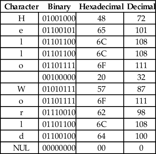
Reading the Binary column from top to bottom results in the following sequence of bytes: 01001000 01100101 01101100 01101100 01101111 00100000 01010111 01101111 01110010 01101100 01100100 0000000. To convert the same string to a hexadecimal representation, we can use the shortcut method that was introduced previously to convert each 4-bit nibble into its hexadecimal equivalent, or read the hexadecimal value from the ASCII table. Table 1.6 shows the result of extending Table 1.5 to include hexadecimal and decimal equivalents for each character. The string can now be converted to hexadecimal or decimal simply by reading the correct column in the table. So “Hello World” expressed as a null-terminated string in hexadecimal is “48 65 6C 6C 6F 20 57 6F 62 6C 64 00” and in decimal it is ”72 101 108 108 111 32 87 111 98 108 100 0”.
Table 1.6
Binary, hexadecimal, and decimal equivalents for each character in “Hello World”
| Character | Binary | Hexadecimal | Decimal |
| H | 01001000 | 48 | 72 |
| e | 01100101 | 65 | 101 |
| l | 01101100 | 6C | 108 |
| l | 01101100 | 6C | 108 |
| o | 01101111 | 6F | 111 |
| 00100000 | 20 | 32 | |
| W | 01010111 | 57 | 87 |
| o | 01101111 | 6F | 111 |
| r | 01110010 | 62 | 98 |
| l | 01101100 | 6C | 108 |
| d | 01100100 | 64 | 100 |
| NUL | 00000000 | 00 | 0 |
Interpreting data as ASCII strings
It is sometimes necessary to convert a string of bytes in hexadecimal into ASCII characters. This is accomplished simply by building a table with the hexadecimal value of each byte in the left column, then looking in the ASCII table for each value and entering the equivalent character representation in the right column. Table 1.7 shows how the ASCII table is used to interpret the hexadecimal string “466162756C6F75732100” as an ASCII string.
ISO extensions to ASCII
ASCII was developed to encode all of the most commonly used characters in North American English text. The encoding uses only 128 of the 256 codes that are available in a 8-bit byte. ASCII does not include symbols frequently used in other countries, such as the British pound symbol (£) or accented characters (ü). However, the International Standards Organization (ISO) has created several extensions to ASCII to enable the representation of characters from a wider variety of languages.
The ISO has defined a set of related standards known collectively as ISO 8859. ISO 8859 is an 8-bit extension to ASCII which includes the 128 ASCII characters along with an additional 128 characters, such as the British Pound symbol and the American cent symbol. Several variations of the ISO 8859 standard exist for different language families. Table 1.8 provides a brief description of the various ISO standards.
Table 1.8
Variations of the ISO 8859 standard
| Name | Alias | Languages |
| ISO8859-1 | Latin-1 | Western European languages |
| ISO8859-2 | Latin-2 | Non-Cyrillic Central and Eastern European languages |
| ISO8859-3 | Latin-3 | Southern European languages and Esperanto |
| ISO8859-4 | Latin-4 | Northern European and Baltic languages |
| ISO8859-5 | Latin/Cyrillic | Slavic languages that use a Cyrillic alphabet |
| ISO8859-6 | Latin/Arabic | Common Arabic language characters |
| ISO8859-7 | Latin/Greek | Modern Greek language |
| ISO8859-8 | Latin/Hebrew | Modern Hebrew languages |
| ISO8859-9 | Latin-5 | Turkish |
| ISO8859-10 | Latin-6 | Nordic languages |
| ISO8859-11 | Latin/Thai | Thai language |
| ISO8859-12 | Latin/Devanagari | Never completed. Abandoned in 1997 |
| ISO8859-13 | Latin-7 | Some Baltic languages not covered by Latin-4 or Latin-6 |
| ISO8859-14 | Latin-8 | Celtic languages |
| ISO8859-15 | Latin-9 | Update to Latin-1 that replaces some characters. Most |
| notably, it includes the euro symbol (€), which did not | ||
| exist when Latin-1 was created | ||
| ISO8859-16 | Latin-10 | Covers several languages not covered by Latin-9 and |
| includes the euro symbol (€) |
Unicode and UTF-8
Although the ISO extensions helped to standardize text encodings for several languages that were not covered by ASCII, there were still some issues. The first issue is that the display and input devices must be configured for the correct encoding, and displaying or printing documents with multiple encodings requires some mechanism for changing the encoding on-the-fly. Another issue has to do with the lexicographical ordering of characters. Although two languages may share a character, that character may appear in a different place in the alphabets of the two languages. This leads to issues when programmers need to sort strings into lexicographical order. The ISO extensions help to unify character encodings across multiple languages, but do not solve all of the issues involved in defining a universal character set.
In the late 1980s, there was growing interest in developing a universal character encoding for all languages. People from several computer companies worked together and, by 1990, had developed a draft standard for Unicode. In 1991, the Unicode Consortium was formed and charged with guiding and controlling the development of Unicode. The Unicode Consortium has worked closely with the ISO to define, extend, and maintain the international standard for a Universal Character Set (UCS). This standard is known as the ISO/IEC 10646 standard. The ISO/IEC 10646 standard defines the mapping of code points (numbers) to glyphs (characters). but does not specify character collation or other language-dependent properties. UCS code points are commonly written in the form U+XXXX, where XXXX in the numerical code point in hexadecimal. For example, the code point for the ASCII DEL character would be written as U+007F. Unicode extends the ISO/IEC standard and specifies language-specific features.
Originally, Unicode was designed as a 16-bit encoding. It was not fully backward-compatible with ASCII, and could encode only 65,536 code points. Eventually, the Unicode character set grew to encompass 1,112,064 code points, which requires 21 bits per character for a straightforward binary encoding. By early 1992, it was clear that some clever and efficient method for encoding character data was needed.
UTF-8 (UCS Transformation Format-8-bit) was proposed and accepted as a standard in 1993. UTF-8 is a variable-width encoding that can represent every character in the Unicode character set using between one and four bytes. It was designed to be backward compatible with ASCII and to avoid the major issues of previous encodings. Code points in the Unicode character set with lower numerical values tend to occur more frequently than code points with higher numerical values. UTF-8 encodes frequently occurring code points with fewer bytes than those which occur less frequently. For example, the first 128 characters of the UTF-8 encoding are exactly the same as the ASCII characters, requiring only 7 bits to encode each ASCII character. Thus any valid ASCII text is also valid UTF-8 text. UTF-8 is now the most common character encoding for the World Wide Web, and is the recommended encoding for email messages.
In November 2003, UTF-8 was restricted by RFC 3629 to end at code point 10FFFF16. This allows UTF-8 to encode 1,114,111 code points, which is slightly more than the 1,112,064 code points defined in the ISO/IEC 10646 standard. Table 1.9 shows how ISO/IEC 10646 code points are mapped to a variable-length encoding in UTF-8. Note that the encoding allows each byte in a stream of bytes to be placed in one of the following three distinct categories:
Table 1.9
UTF-8 encoding of the ISO/IEC 10646 code points
| First | Last | ||||||
| UCS | Code | Code | |||||
| Bits | Point | Point | Bytes | Byte 1 | Byte 2 | Byte 3 | Byte 4 |
| 7 | U+0000 | U+007F | 1 | 0xxxxxxx | |||
| 11 | U+0080 | U+07FF | 2 | 110xxxxx | 10xxxxxx | ||
| 16 | U+0800 | U+FFFF | 3 | 1110xxxx | 10xxxxxx | 10xxxxxx | |
| 21 | U+10000 | U+10FFFF | 4 | 11110xxx | 10xxxxxx | 10xxxxxx | 10xxxxxx |
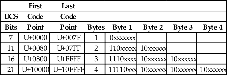
1. If the most significant bit of a byte is zero, then it is a single-byte character, and is completely ASCII-compatible.
2. If the two most significant bits in a byte are set to one, then the byte is the beginning of a multi-byte character.
3. If the most significant bit is set to one, and the second most significant bit is set to zero, then the byte is part of a multi-byte character, but is not the first byte in that sequence.
The UTF-8 encoding of the UCS characters has several important features:
Backwards compatible with ASCII: This allows the vast number of existing ASCII documents to be interpreted as UTF-8 documents without any conversion.
Self-synchronization: Because of the way code points are assigned, it is possible to find the beginning of each character by looking only at the top two bits of each byte. This can have important performance implications when performing searches in text.
Encoding of code sequence length: The number of bytes in the sequence is indicated by the pattern of bits in the first byte of the sequence. Thus, the beginning of the next character can be found quickly. This feature can also have important performance implications when performing searches in text.
Efficient code structure: UTF-8 efficiently encodes the UCS code points. The high-order bits of the code point go in the lead byte. Lower-order bits are placed in continuation bytes. The number of bytes in the encoding is the minimum required to hold all the significant bits of the code point.
Easily extended to include new languages: This feature will be greatly appreciated when we contact intelligent species from other star systems.
With UTF-8 encoding, the first 128 characters of the UCS are each encoded in a single byte. The next 1,920 characters require two bytes to encode. The two-byte encoding covers almost all Latin alphabets, and also Arabic, Armenian, Cyrillic, Coptic, Greek, Hebrew, Syriac and Tāna alphabets. It also includes combining diacritical marks, which are used in combination with another character, such as á, ñ, and ö. Most of the Chinese, Japanese, and Korean (CJK) characters are encoded using three bytes. Four bytes are needed for the less common CJK characters, various historic scripts, mathematical symbols, and emoji (pictographic symbols).
Consider the UTF-8 encoding for the British Pound symbol (£), which is UCS code point U+00A3. Since the code point is greater than 7F16, but less than 80016, it will require two bytes to encode. The encoding will be 110xxxxx 10xxxxxx, where the x characters are replaced with the 11 least-significant bits of the code point, which are 00010100011. Thus, the character £ is encoded in UTF-8 as 11000010 10100011 in binary, or C2 A3 in hexadecimal.
The UCS code point for the Euro symbol (€) is U+20AC. Since the code point is between 80016 and FFFF16, it will require three bytes to encode in UTF-8. The three-byte encoding is 1110xxxx 10xxxxxx 10xxxxxx where the x characters are replaced with the 16 least-significant bits of the code point. In this case the code point, in binary is 0010000010101100. Therefore, the UTF-8 encoding for € is 11100010 10000010 10101100 in binary, or E2 82 AC in hexadecimal.
In summary, there are three components to modern language support. The ISO/IEC 10646 defines a mapping from code points (numbers) to glyphs (characters). UTF-8 defines an efficient variable-length encoding for code points (text data) in the ISO/IEC 10646 standard. Unicode adds language specific properties to the ISO/IEC 10646 character set. Together, these three elements currently provide support for textual data in almost every human written language, and they continue to be extended and refined.
1.4 Memory Layout of an Executing Program
Computer memory consists of number of storage locations, or cells, each of which has a unique numeric address. Addresses are usually written in hexadecimal. Each storage location can contain a fixed number of binary digits. The most common size is one byte. Most computers group bytes together into words. A computer CPU that is capable of accessing a single byte of memory is said to have byte addressable memory. Some CPUs are only capable of accessing memory in word-sized groups. They are said to have word addressable memory.
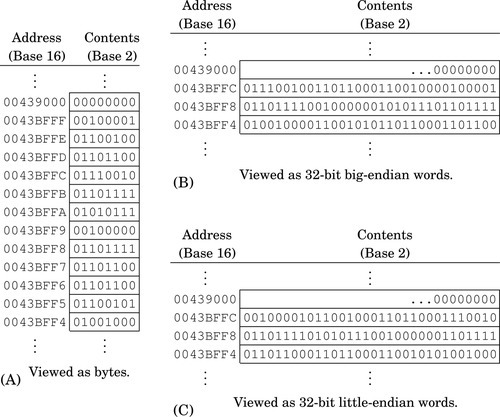
Fig. 1.6 A shows a section of memory containing some data. Each byte has a unique address that is used when data is transferred to or from that memory cell. Most processors can also move data in word-sized chunks. On a 32-bit system, four bytes are grouped together to form a word. There are two ways that this grouping can be done. Systems that store the most significant byte of a word in the smallest address, and the least significant byte in the largest address, are said to be big-endian. The big-endian interpretation of a region of memory is shown in Fig. 1.6B. As shown in Fig. 1.6C, little-endian systems store the least significant byte in the lowest address and the most significant byte in the highest address. Some processors, such as the ARM, can be configured as either little-endian or big-endian. The Linux operating system, by default, configures the ARM processor to run in little-endian mode .
The memory layout for a typical program is shown in Fig. 1.7. The program is divided into four major memory regions, or sections. The programmer specifies the contents of the Text and Data sections. The Stack and Heap segments are defined when the program is loaded for execution. The Stack and Heap may grow and shrink as the program executes, while the Text and Data segments are set to fixed sizes by the compiler, linker, and loader. The Text section contains the executable instructions, while the Data section contains constants and statically allocated variables. The sizes of the Text and Data segments depend on how large the program is, and how much static data storage has been declared by the programmer. The heap contains variables that are allocated dynamically, and the stack is used to store parameters for function calls, return addresses, and local (automatic) variables.
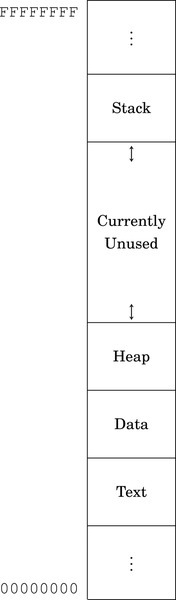
In a high-level language, storage space for a variable can be allocated in one of three ways: statically, dynamically, and automatically. Statically allocated variables are allocated from the .data section. The storage space is reserved, and usually initialized, when the program is loaded and begins execution. The address of a statically allocated variable is fixed at the time the program begins running, and cannot be changed. Automatically allocated variables, often referred to as local variables, are stored on the stack. The stack pointer is adjusted down to make space for the newly allocated variable. The address of an automatic variable is always computed as an offset from the stack pointer. Dynamic variables are allocated from the heap, using malloc, new, or a language-dependent equivalent. The address of a dynamic variable is always stored in another variable, known as a pointer, which may be an automatic or static variable, or even another dynamic variable. The four major sections of program memory correspond to executable code, statically allocated variables, dynamically allocated variables, and automatically allocated variables.
1.5 Chapter Summary
There are several reasons for Computer Scientists and Computer Engineers to learn at least one assembly language. There are programming tasks that can only be performed using assembly language, and some tasks can be written to run much more efficiently and/or quickly if written in assembly language. Programmers with assembly language experience tend to write better code even when using a high-level language, and are usually better at finding and fixing bugs.
Although it is possible to construct a computer capable of performing arithmetic in any base, it is much cheaper to build one that works in base two. It is relatively easy to build an electrical circuit with two states, using two discrete voltage levels, but much more difficult to build a stable circuit with 10 discrete voltage levels. Therefore, modern computers work in base two.
Computer data can be viewed as simple bit strings. The programmer is responsible for supplying interpretations to give meaning to those bit strings. A set of bits can be interpreted as a number, a character, or anything that the programmer chooses. There are standard methods for encoding and interpreting characters and numbers. Fig. 1.4 shows some common methods for encoding integers. The most common encodings for characters are UTF-8 and ASCII.
Computer memory can be viewed as a sequence of bytes. Each byte has a unique address. A running program has four regions of memory. One region holds the executable code. The other three regions hold different types of variables.
Exercises
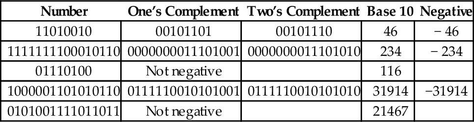
1.1 What is the two’s complement of 11011101?
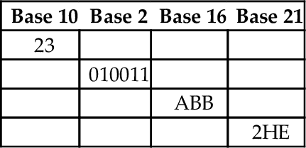
1.2 Perform the base conversions to fill in the blank spaces in the following table:
1.3 What is the 8-bit ASCII binary representation for the following characters?
(b) “a”
(c) “!”
1.4 What is \ minus ! given that \ and ! are ASCII characters? Give your answer in binary.
(a) Convert the string “Super!” to its ASCII representation. Show your result as a sequence of hexadecimal values.
(b) Convert the hexadecimal sequence into a sequence of values in base four.
1.6 Suppose that the string “This is a nice day” is stored beginning at address 4B3269AC16. What are the contents of the byte at address 4B3269B116 in hexadecimal?
(a) Convert 1011012 to base ten.
(b) Convert 102310 to base nine.
(c) Convert 102310 to base two.
(d) Convert 30110 to base 16.
(e) Convert 30110 to base 2.
(f) Represent 30110 as a null-terminated ASCII string (write your answer in hexadecimal).
(g) Convert 34205 to base ten.
(h) Convert 23145 to base nine.
(i) Convert 1167 to base three.
(j) Convert 129411 to base 5.
1.8 Given the following binary string:
01001001 01110011 01101110 00100111 01110100 00100000 01000001 01110011 01110011 01100101 01101101 01100010 01101100 01111001 00100000 01000110 01110101 01101110 00111111 00000000
(a) Convert it to a hexadecimal string.
(b) Convert the first four bytes to a string of base ten numbers.
(c) Convert the first (little-endian) halfword to base ten.
(d) Convert the first (big-endian) halfword to base ten.
(e) If this string of bytes were sent to an ASCII printer or terminal, what would be printed?
1.9 The number 1,234,567 is stored as a 32-bit word starting at address F043900016. Show the address and contents of each byte of the 32-bit word on a
(b) big-endian system.
1.10 The ISO/IEC 10646 standard defines 1,112,064 code points (glyphs). Each code point could be encoded using 24 bits, or three bytes. The UTF-8 encoding uses up to four bytes to encode a code point. Give three reasons why UTF-8 is preferred over a simple 3-byte per code point encoding.
1.11 UTF-8 is often referred to as Unicode. Why is this not correct?
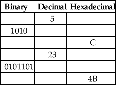
1.12 Skilled assembly programmers can convert small numbers between binary, hexadecimal, and decimal in their heads. Without referring to any tables or using a calculator or pencil, fill in the blanks in the following table:
1.13 What are the differences between a CPU register and a memory location?