Table of Contents for
Modern Assembly Language Programming with the ARM Processor
 Modern Assembly Language Programming with the ARM Processor
Published by
Newnes, 2016
Modern Assembly Language Programming with the ARM Processor
Published by
Newnes, 2016
- Modern Assembly Language Programming with the ARM Processor
- Cover image
- Title page
- Table of Contents
- Copyright
- List of Tables
- List of Figures
- List of Listings
- Preface
- Companion Website
- Acknowledgments
- Part I: Assembly as a Language
- Chapter 1: Introduction
- Chapter 2: GNU Assembly Syntax
- Chapter 3: Load/Store and Branch Instructions
- Chapter 4: Data Processing and Other Instructions
- Chapter 5: Structured Programming
- Chapter 6: Abstract Data Types
- Part II: Performance Mathematics
- Chapter 7: Integer Mathematics
- Chapter 8: Non-Integral Mathematics
- Chapter 9: The ARM Vector Floating Point Coprocessor
- Chapter 10: The ARM NEON Extensions
- 10.10 Multiplication and Division
- Part III: Accessing Devices
- Chapter 11: Devices
- Chapter 12: Pulse Modulation
- Chapter 13: Common System Devices
- Chapter 14: Running Without an Operating System
- Index
Load/Store and Branch Instructions
Abstract
This chapter explains how a particular assembly language is related to the architectural design of a particular CPU family. It then gives an overview of the ARM architecture. Next, it describes the ARM register set and data paths, including the Process Status Register, and the flags which are used to control conditional execution. Then it introduces the concept of instructions and operands, and explains immediate data used as an operand. Next it describes the load and store instructions and all of the addressing modes available on the ARM processor. Then it explains the branch and conditional branch instructions. The chapter ends with some examples showing how the branch and link instruction can be used to call functions from the C standard library.
Keywords
Architecture; Instruction set architecture; Data path; Register; Memory; Load; Store; Branch; Address; Addressing mode; Conditional execution; Function or subroutine call
The part of the computer architecture related to programming is referred to as the instruction set architecture (ISA). The ISA includes the set of registers that the user program can access, and the set of instructions that the processor supports, as well as data paths and processing elements within the processor. The first step in learning a new assembly language is to become familiar with the ISA. For most modern computer systems, data must be loaded in a register before it can be used for any data processing instruction, but there are a limited number of registers. Memory provides a place to store data that is not currently needed. Program instructions are also stored in memory and fetched into the CPU as they are needed. This chapter introduces the ISA for the ARM processor.
3.1 CPU Components and Data Paths
The CPU is composed of data storage and computational components connected together by a set of buses. The most important components of the CPU are the registers, where data is stored, and the arithmetic and logic unit (ALU), where arithmetic and logical operations are performed on the data. Some CPUs also have dedicated hardware units for multiplication and/or division. Fig. 3.1 shows the major components of the ARM CPU and the buses that connect the components together. These buses provide pathways for the data to move between the computational and storage components. The organization of the components and buses in a CPU govern what types of operations can be performed.
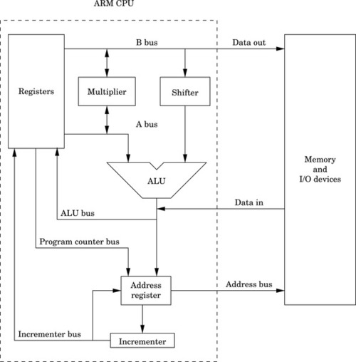
The set of instructions and addressing modes available on the ARM processor is closely related to the architecture shown in Fig. 3.1. The architecture provides for certain operations to be performed efficiently, and this has a direct relationship to the types of instructions that are supported.
Note that on the ARM, two source registers can be selected for an instruction, using the A and B buses. The data on the B bus is routed through a shifter, and then to the ALU. This allows the second operand of most instructions to be shifted an arbitrary amount before it reaches the ALU. The data on the A bus goes directly to the ALU. Additionally, the A and B buses can provide operands for the multiplier, and the multiplier can provide data for the A and B buses.
Data coming in from memory or an input/output device is fed directly onto the ALU bus. From there, it can be stored in one of the general-purpose registers. Data being written to memory or an input/output device is taken directly from the B bus, which means that store operations can move data from a register, but cannot modify the data on the way to memory or input/output devices.
The address register is a temporary register that is used by the CPU whenever it needs to read or write to memory or I/O devices. It is used every time an instruction is fetched from memory, and is used for all load and store operations. The address register can be loaded from the program counter, for fetching the next instruction. Also the address register can be loaded from the ALU, which allows the processor to support addressing modes where a register is used as a base pointer and an offset is calculated on-the-fly. After its contents are used to access memory or I/O devices, the base address can be incremented and the incremented value can be stored back into a register. This allows the processor to increment the program counter after each instruction, and to implement certain addressing modes where a pointer is automatically incremented after each memory access.
3.2 ARM User Registers
As shown in Fig. 3.2, the ARM processor provides 13 general-purpose registers, named r0 through r12. These registers can each store 32 bits of data. In addition to the 13 general-purpose registers, the ARM has three other special-purpose registers.
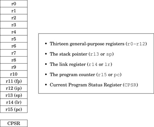
The program counter, r15, always contains the address of the next instruction that will be executed. The processor increments this register by four, automatically, after each instruction is fetched from memory. By moving an address into this register, the programmer can cause the processor to fetch the next instruction from the new address. This gives the programmer the ability to jump to any address and begin executing code there.
The link register, r14, is used to hold the return address for subroutines. Certain instructions cause the program counter to be copied to the link register, then the program counter is loaded with a new address. These branch-and-link instructions are briefly covered in Section 3.5 and in more detail in Section 5.4.
The program stack was introduced in Section 1.4. The stack pointer, r13, is used to hold the address where the stack ends. This is commonly referred to as the top of the stack, although on most systems the stack grows downwards and the stack pointer really refers to the bottom of the stack. The address where the stack ends may change when registers are pushed onto the stack, or when temporary local variables (automatic variables) are allocated or deleted. The use of the stack for storing automatic variables is described in Chapter 5. The use of r13 as the stack pointer is a programming convention. Some instructions (eg, branches) implicitly modify the program counter and link registers, but there are no special instructions involving the stack pointer. As far as the hardware is concerned, r13 is exactly the same as registers r0–r12, but all ARM programmers use it for the stack pointer.
Although register r13 is normally used as the stack pointer, it can be used as a general-purpose register if the stack is not used. However the high-level language compilers always use it as the stack pointer, so using it as a general-purpose register will result in code that cannot inter-operate with code generated using high-level languages. The link register, r14, can also be used as a general-purpose register, but its contents are modified by hardware when a subroutine is called. Using r13 and r14 as general-purpose registers is dangerous and strongly discouraged.
There are also two other registers which may have special purposes. As with the stack pointer, these are programming conventions. There are no special instructions involving these registers. The frame pointer (r11) is used by high-level language compilers to track the current stack frame. This is sometimes useful when running your program under a debugger, and can sometimes help the compiler to generate more efficient code for returning from a subroutine. The GNU C compiler can be instructed to use r11 as a general-purpose register by using the --omit-frame-pointer command line option. The inter-procedure scratch register r12 is used by the C library when calling functions in dynamically linked libraries. The contents may change, seemingly at random, when certain functions (such as printf) are called.
The final register in the ARM user programming model is the Current Program Status Register (CPSR). This register contains bits that indicate the status of the current program, including information about the results of previous operations. Fig. 3.3 shows the bits in the CPSR. The first four bits, N, Z, C, and V are the condition flags. Most instructions can modify these flags, and later instructions can use the flags to modify their operation. Their meaning is as follows:

Negative: This bit is set to one if the signed result of an operation is negative, and set to zero if the result is positive or zero.
Zero: This bit is set to one if the result of an operation is zero, and set to zero if the result is non-zero.
Carry: This bit is set to one if an add operation results in a carry out of the most significant bit, or if a subtract operation results in a borrow. For shift operations, this flag is set to the last bit shifted out by the shifter.
oVerflow: For addition and subtraction, this flag is set if a signed overflow occurred.
The remaining bits are used by the operating system or for bare-metal programs, and are described in Section 14.1.
3.3 Instruction Components
The ARM processor supports a relatively small set of instructions grouped into four basic instruction types. Most instructions have optional modifiers which can be used to change their behavior. For example, many instructions can have modifiers which set or check condition codes in the CPSR. The combination of basic instructions with optional modifiers results in an extremely rich assembly language. There are four general instruction types, or categories. The following sections give a brief overview of the features which are common to instructions in each category. The individual instructions are explained later in this chapter, and in the following chapter.
3.3.1 Setting and Using Condition Flags
As mentioned previously, the CPSR contains four flag bits (bits 28–31), which can be used to control whether or not certain instructions are executed. Most of the data processing instructions have an optional modifier to control whether or not the flag bits are affected when the instruction is executed. For example, the basic instruction for addition is add. When the add instruction is executed, the result is stored in a register, but the flag bits in the CPSR are not affected.
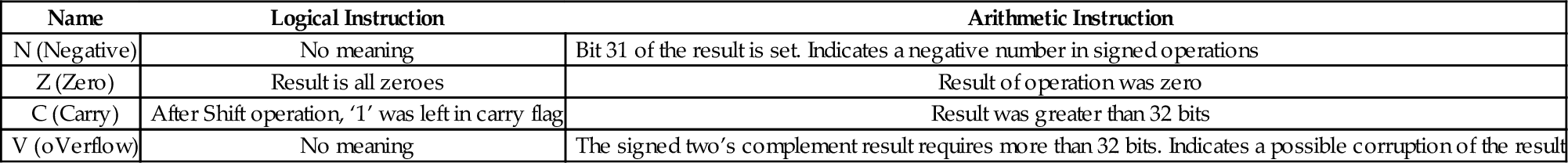
However, the programmer can add the s modifier to the add instruction to create the adds instruction. When it is executed, this instruction will affect the CPSR flag bits. The flag bits can be used by subsequent instructions to control execution and branching. The meaning of the flags depends on the type of instruction that last set the flags. Table 3.1 shows the names and meanings of the four bits depending on the type of instruction that set or cleared them. Most instructions support the s modifier to control setting the flags.
Table 3.1
Flag bits in the CPSR register
| Name | Logical Instruction | Arithmetic Instruction |
| N (Negative) | No meaning | Bit 31 of the result is set. Indicates a negative number in signed operations |
| Z (Zero) | Result is all zeroes | Result of operation was zero |
| C (Carry) | After Shift operation, ‘1’ was left in carry flag | Result was greater than 32 bits |
| V (oVerflow) | No meaning | The signed two’s complement result requires more than 32 bits. Indicates a possible corruption of the result |
Most ARM instructions can have a condition modifier attached. If present, the modifier controls, at run-time, whether or not the instruction is actually executed. These condition modifiers are added to basic instructions to create conditional instructions. Table 3.2 shows the condition modifiers that can be attached to base instructions. For example, to create an instruction that adds only if the CPSR Z flag is set, the programmer would add the eq condition modifier to the basic add instruction to create the addeq instruction.
Table 3.2
ARM condition modifiers
| <cond> | English Meaning |
| al | always (this is the default <cond> |
| eq | Z set (=) |
| ne | Z clear (≠) |
| ge | N set and V set, or N clear and V clear (≥) |
| lt | N set and V clear, or N clear and V set (<) |
| gt | Z clear, and either N set and V set, or N clear and V set (>) |
| le | Z set, or N set and V clear, or N clear and V set (≤) |
| hi | C set and Z clear (unsigned >) |
| ls | C clear or Z (unsigned ≤) |
| hs | C set (unsigned ≥) |
| cs | Alternate name for HS |
| lo | C clear (unsigned <) |
| cc | Alternate name for LO |
| mi | N set (result < 0) |
| pl | N clear (result ≥ 0) |
| vs | V set (overflow) |
| vc | V clear (no overflow) |
Setting and using condition flags are orthogonal operations. This means that they can be used in combination. Using the previous example, the programmer could add the s modifier to create the addeqs instruction, which executes only if the Z bit is set, and updates the CPSR flags only if it executes.
3.3.2 Immediate Values
An immediate value in assembly language is a constant value that is specified by the programmer. Some assembly languages encode the immediate value as part of the instruction. Other assembly languages create a table of immediate values in a literal pool and insert appropriate instructions to access them. ARM assembly language provides both methods.
Immediate values can be specified in decimal, octal, hexadecimal, or binary. Octal values must begin with a zero, and hexadecimal values must begin with “0x”. Likewise immediate values that start with “0b” are interpreted as binary numbers. Any value that does not begin with zero, 0x, or 0 b will be interpreted as a decimal value.
There are two ways that immediate values can be specified in GNU ARM assembly. The =<immediate|symbol> syntax can be used to specify any immediate 32-bit number, or to specify the 32-bit value of any symbol in the program. Symbols include program labels (such as main) and symbols that are defined using .equ and similar assembler directives. However, this syntax can only be used with load instructions, and not with data processing instructions. This restriction is necessary because of the way the ARM machine instructions are encoded. For data processing instructions, there are a limited number of bits that can be devoted to storing immediate data as part of the instruction.
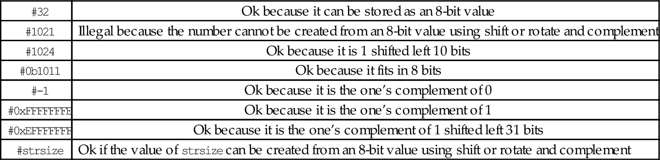
The #<immediate|symbol> syntax is used to specify immediate data values for data processing instructions. The #<immediate|symbol> syntax has some restrictions. Basically, the assembler must be able to construct the specified value using only eight bits of data, a shift or rotate, and/or a complement. For immediate values that can cannot be constructed by shifting or rotating and complementing an 8-bit value, the programmer must use an ldr instruction with the =<immediate|symbol> to specify the value. That method is covered in Section 3.4. Some examples of immediate values are shown in Table 3.3.
Table 3.3
Legal and illegal values for #<immediate—symbol>
| #32 | Ok because it can be stored as an 8-bit value |
| #1021 | Illegal because the number cannot be created from an 8-bit value using shift or rotate and complement |
| #1024 | Ok because it is 1 shifted left 10 bits |
| #0b1011 | Ok because it fits in 8 bits |
| #-1 | Ok because it is the one’s complement of 0 |
| #0xFFFFFFFE | Ok because it is the one’s complement of 1 |
| #0xEFFFFFFF | Ok because it is the one’s complement of 1 shifted left 31 bits |
| #strsize | Ok if the value of strsize can be created from an 8-bit value using shift or rotate and complement |
3.4 Load/Store Instructions
The ARM processor has a strict separation between instructions that perform computation and those that move data between the CPU and memory. Because of this separation between load/store operations and computational operations, it is a classic example of a load-store architecture. The programmer can transfer bytes (8 bits), half-words (16 bits), and words (32 bits), from memory into a register, or from a register into memory. The programmer can also perform computational operations (such as adding) using two source operands and one register as the destination for the result. All computational instructions assume that the registers already contain the data. Load instructions are used to move data into the registers, while store instructions are used to move data from the registers to memory.
3.4.1 Addressing Modes
Most of the load/store instructions use an <address> which is one of the six options shown in Table 3.4. The < shift_op > can be any of shift operations from Table 3.5, and shift should be a number between 0 and 31. Although there are really only six addressing modes, there are eleven variations of the assembly language syntax. Four of the variations are simply shorthand notations. One of the variations allows an immediate data value or the address of a label to be loaded into a register, and may result in the assembler generating more than one instruction. The following section describes each addressing mode in detail.
Table 3.4
ARM addressing modes
| Syntax | Name |
| [Rn, #±<offset_12>] | Immediate offset |
| [Rn, ±Rm, <shift_op> #<shift>] | Scaled register offset |
| [Rn, #±<offset_12>]! | Immediate pre-indexed |
| [Rn, ±Rm, <shift_op> #<shift>]! | Scaled register pre-indexed |
| [Rn], #±<offset_12> | Immediate post-indexed |
| [Rn], ±Rm, <shift_op> #<shift> | Scaled register post-indexed |
Table 3.5
ARM shift and rotate operations
| <shift> | Meaning |
| lsl | Logical Shift Left by specified amount |
| lsr | Logical Shift Right by specified amount |
| asr | Arithmetic Shift Right by specified amount |
Immediate offset: [Rn, #±< offset_12 >]
The immediate offset (which may be positive or negative) is added to the contents of Rn. The result is used as the address of the item to be loaded or stored. For example, the following line of code:
calculates a memory address by adding 12 to the contents of register r1. It then loads four bytes of data, starting at the calculated memory address, into register r0. Similarly, the line:
subtracts 8 from the contents of r6 and uses that as the address where it stores the contents of r9 in memory.
Register immediate: [Rn]
When using immediate offset mode with an offset of zero, the comma and offset can be omitted. That is, [Rn] is just shorthand notation for [Rn, #0]. This shorthand is referred to as register immediate mode. For example, the following line of code:
uses the contents of register r2 as a memory address and loads four bytes of data, starting at that address, into register r3. Likewise,
copies the contents of r8 to the four bytes of memory starting at the address that is in r0.
Scaled register offset: [Rn, ±Rm, < shift_op > #<shift>]
Rm is shifted as specified, then added to or subtracted from Rn. The result is used as the address of the item to be loaded or stored. For example,
shifts the contents of r1 left two bits, adds the result to the contents of r2 and uses the sum as an address in memory from which it loads four bytes into r3. Recall that shifting a binary number left by two bits is equivalent to multiplying that number by four. This addressing mode is typically used to access an array, where r2 contains the address of the beginning of the array, and r1 is an integer index. The integer shift amount depends on the size of the objects in the array. To store an item from register r0 into an array of half-words, the following instruction could be used:
where r4 holds the address of the first byte of the array, and r5 holds the integer index for the desired array item.
Register offset: [Rn, ±Rm]
When using scaled register offset mode with a shift amount of zero, the comma and shift specification can be omitted. That is, [Rn, ±Rm] is just shorthand notation for [Rn, ±Rm, lsl #0]. This shorthand is referred to as register offset mode.
Immediate pre-indexed: [Rn, #±Rm< offset_12 >]!
The address is computed in the same way as immediate offset mode, but after the load or store, the address that was used is stored in Rn. This mode can be used to step through elements in an array, updating a pointer to the next array element before each element is accessed.
Scaled register pre-indexed: [Rn, ±Rm, < shift_op > #<shift>]!
The address is computed in the same way as scaled register offset mode, but after the load or store, the address that was used is stored in Rn. This mode can be used to step through elements in an array, updating a pointer to the current array element before each access.
Register pre-indexed: [Rn, ±Rm]!
When using scaled register pre-indexed mode with a shift amount of zero, the comma and shift specification can be omitted. That is, [Rn, ±Rm]! is shorthand notation for [Rn, ±Rm, lsl #0]!. This shorthand is referred to as register pre-indexed mode.
Immediate post-indexed: [Rn], #±< offset_12 >
Register Rn is used as the address of the value to be loaded or stored. After the value is loaded or stored, the value in Rn is updated by adding the immediate offset, which may be negative or positive. This mode can be used to step through elements in an array, updating a pointer to point at the next array element after each one is accessed.
Scaled register post-indexed: [Rn], ±Rm, < shift_op > #<shift>
Register Rn is used as the address of the value to be loaded or stored. After the value is loaded or stored, the value in Rn is updated by adding or subtracting the contents of Rm shifted as specified. This mode can be used to step through elements in an array, updating a pointer to point at the next array element after each one is accessed.
Register post-indexed: [Rn], ±Rm
When using scaled register post-indexed mode with a shift amount of zero, the comma and shift specification can be omitted. That is, [Rn], ±Rm is shorthand notation for [Rn], ±Rm, lsl #0. This shorthand is referred to as register post-indexed mode.
Load Immediate: [Rn], =<immediate|symbol>
This is really a pseudo-instruction. The assembler will generate a mov instruction if possible. Otherwise it will store the value of immediate or the address of symbol in a “literal table” and generate a load instruction, using one of the previous addressing modes, to load the value into a register. This addressing mode can only be used with the ldr instruction.
The load and store instructions allow the programmer to move data from memory to registers or from registers to memory. The load/store instructions can be grouped into the following types:
• multiple register, and
• atomic.
The following sections describe the seven load and store instructions that are available, and all of their variations.
3.4.2 Load/Store Single Register
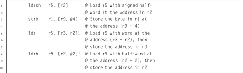
These instructions transfer a single word, half-word, or byte from a register to memory or from memory to a register:
str Store Register.
Syntax
• The optional <cond> can be any of the codes from Table 3.2 on page 59 specifying conditional execution.
• The optional <size> is one of:
h unsigned half-word
sb signed byte
sh signed half-word
• The <address> is any valid address specifier described in Section 3.4.1.
Operations
Examples
3.4.3 Load/Store Multiple Registers
ARM has two instructions for loading and storing multiple registers:
ldm Load Multiple Registers, and
stm Store Multiple Registers.
These instructions are used to store registers on the program stack, and for copying blocks of data. The ldm and stm instructions each have four variants, and each variant has two equivalent names. So, although there are only two basic instructions, there are sixteen mnemonics. These are the most complex instructions in the ARM assembly language.
Syntax
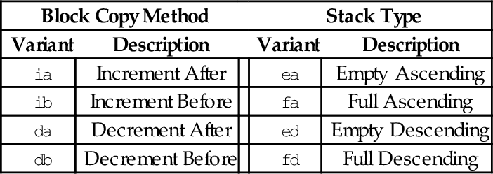
• <variant> is chosen from the following tables:
| Block Copy Method | Stack Type | |||
| Variant | Description | Variant | Description | |
| ia | Increment After | ea | Empty Ascending | |
| ib | Increment Before | fa | Full Ascending | |
| da | Decrement After | ed | Empty Descending | |
| db | Decrement Before | fd | Full Descending | |
• The optional ! specifies that the address register Rd should be modified after the registers are stored.
• An optional trailing ˆ can only be used by operating system code. It causes the transfer to affect user registers instead of operating system registers.
There are two equivalent mnemonics for each load/store multiple instruction. For example, ldmia is exactly the same instruction as ldmfd, and stmdb is exactly the same instruction as stmfd. There are two different names so that the programmer can indicate what the instruction is being used for.
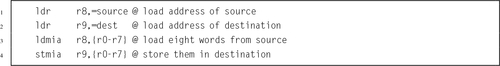
The mnemonics in the Block Copy Method table are used when the programmer is using the instructions to move blocks of data. For instance, the programmer may want to copy eight words from one address in memory to another address. One very efficient way to do that is to:
1. load the address of the first byte of the source into a register,
2. load the address of the first byte of the destination into another register,
3. use ldmia (load multiple increment after) to load eight registers from the source address, then
4. use stmia (store multiple increment after) to store the registers to the destination address.
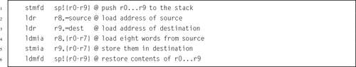
Assuming source and dest are labeled blocks of data declared elsewhere, the following listing shows the exact instructions needed to move eight words from source to dest:
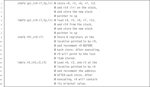
The mnemonics in the Stack Type table are used when the programmer is performing stack operations. The most common variants are stmfd and ldmfd, which are used for pushing registers onto the program stack and later popping them back off, respectively. In Linux, the C compiler always uses the stmfd and ldmfd versions for accessing the stack. The following code shows how the programmer could save the contents of registers r0-r9 on the stack, use them to perform a block copy, then restore their contents:
Note that in the previous example, after the stmfd sp!, { r0-r9 } instruction, sp will contain the address of the last word on the stack, because the optional ! was used to indicate that the register should be updated.
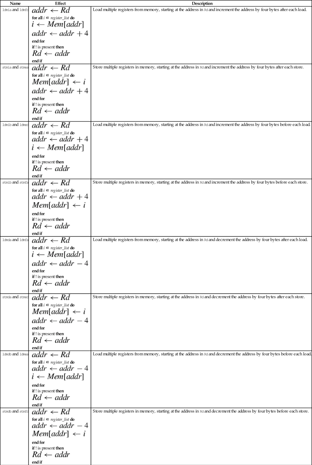
Operations
| Name | Effect | Description |
| ldmia and ldmfd |
for all i ∈ register_list do
end for if ! is present then
end if | Load multiple registers from memory, starting at the address in Rd and increment the address by four bytes after each load. |
| stmia and stmea |
for all i ∈ register_list do
end for if ! is present then
end if | Store multiple registers in memory, starting at the address in Rd and increment the address by four bytes after each store. |
| ldmib and ldmed |
for all i ∈ register_list do
end for if ! is present then
end if | Load multiple registers from memory, starting at the address in Rd and increment the address by four bytes before each load. |
| stmib and stmfa |
for all i ∈ register_list do
end for if ! is present then
end if | Store multiple registers in memory, starting at the address in Rd and increment the address by four bytes before each store. |
| ldmda and ldmfa |
for all i ∈ register_list do
end for if ! is present then
end if | Load multiple registers from memory, starting at the address in Rd and decrement the address by four bytes after each load. |
| stmda and stmed |
for all i ∈ register_list do
end for if ! is present then
end if | Store multiple registers in memory, starting at the address in Rd and decrement the address by four bytes after each store. |
| ldmdb and ldmea |
for all i ∈ register_list do
end for if ! is present then
end if | Load multiple registers from memory, starting at the address in Rd and decrement the address by four bytes before each load. |
| stmdb and stmfd |
for all i ∈ register_list do
end for if ! is present then
end if | Store multiple registers in memory, starting at the address in Rd and decrement the address by four bytes before each store. |


Examples
3.4.4 Swap
Multiprogramming and threading require the ability to set and test values atomically. This instruction is used by the operating system or threading libraries to guarantee mutual exclusion:
Note: swp and swpb are deprecated in favor of ldrex and strex, which work on multiprocessor systems as well as uni-processor systems.
Syntax
• The optional s specifies whether or not the instruction should affect the bits in the CPSR.
• The optional <cond> can be any of the codes from Table 3.2 specifying conditional execution.
Operations


Example
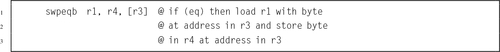
3.4.5 Exclusive Load/Store
These instructions are used by the operating system or threading libraries to guarantee mutual exclusion, even on multiprocessor systems:
ldrex Load Multiple Registers, and
strex Store Multiple Registers.
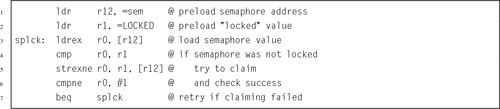
Exclusive load (ldrex) reads data from memory, tagging the memory address at the same time. Exclusive store (strex) stores data to memory, but only if the tag is still valid. A strex to the same address as the previous ldrex will invalidate the tag. A str to the same address may invalidate the tag (implementation defined). The strex instruction sets a bit in the specified register which indicates whether or not the store succeeded. This allows the programmer to implement semaphores on uni-processor and multiprocessor systems.
Syntax
• The optional <cond> can be any of the codes from Table 3.2 specifying conditional execution.
Operations


Example
3.5 Branch Instructions
Branch instructions allow the programmer to change the address of the next instruction to be executed. They are used to implement loops, if-then structures, subroutines, and other flow control structures. There are two basic branch instructions:
• Branch and Link (subroutine call).
3.5.1 Branch
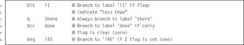
This instruction is used to perform conditional and unconditional branches in program execution:
It is used for creating loops and if-then-else constructs.
Syntax
• The optional <cond> can be any of the codes from Table 3.2 specifying conditional execution.
• The target_label can be any label in the current file, or any label that is defined as .global or .globl in any file that is linked in.
Operations

Examples
3.5.2 Branch and Link
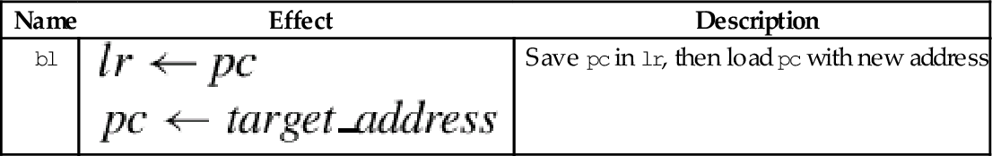
The following instruction is used to call subroutines:
The branch and link instruction is identical to the branch instruction, except that it copies the current program counter to the link register before performing the branch. This allows the programmer to copy the link register back into the program counter at some later point. This is how subroutines are called, and how subroutines return and resume executing at the next instruction after the one that called them.
Syntax
• The optional <cond> can be any of the codes from Table 3.2 specifying conditional execution.
• The target_address can be any label in the current file, or any label that is defined as .global or .globl in any file that is linked in.
Operations

Examples

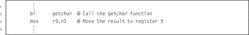
Example 3.1 shows how the bl instruction can be used to call a function from the C standard library to read a single character from standard input. By convention, when a function is called, it will leave its return value in r0. Example 3.2 shows how the bl instruction can be used to call another function from the C standard library to print a message to standard output. By convention, when a function is called, it will expect to find its first argument in r0. There are other rules, which all ARM programmers must follow, regarding which registers are used when passing arguments to functions and procedures. Those rules will be explained fully in Section 5.4.
Example 3.1
Using the bl Instruction to Read a Character
Suppose we want to read a single character from standard input. This can be accomplished in C by calling the getchar () function from the C standard library as follows:
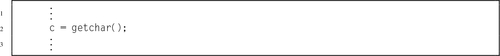
The above C code assumes that the variable c has been declared to hold the result of the function. In ARM assembly language, functions always return their results in r0. The assembly programmer may then move the result to any register or memory location they choose. In the following example, it is assumed that r9 was chosen to hold the value of the variable c:
Example 3.2
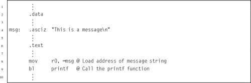
Using the bl Instruction to Print a Message
To print a string to standard output in C, we can use the printf () function from the C standard library as follows:
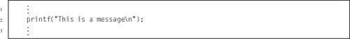
The C compiler will automatically create a constant array of characters and initialize it to hold the message. Then it will load the address of the first character in the array into register r0 before calling printf (). The printf () function will expect to see an address in r0, which it will assume is the address of the format string to be printed. The function call can be made as follows in ARM assembly:
3.6 Pseudo-Instructions
The assembler provides a small number of pseudo-instructions. From the perspective of the programmer, these instructions are indistinguishable from standard instructions. However, when the assembler encounters a pseudo-instruction, it may substitute a different instruction or generate a short sequence of machine instructions.
3.6.1 Load Immediate
This pseudo-instruction loads a register with any 32-bit value:
When this pseudo-instruction is encountered, the assembler first determines whether or not it can substitute a mov Rd,#<immediate> or mvn Rd,#<immediate> instruction. If that is not possible, then it reserves four bytes in a “literal pool” and stores the immediate value there. Then, the pseudo-instruction is translated into an ldr instruction using Immediate Offset addressing mode with the pc as the base register.
Syntax
• The optional <cond> can be any of the codes from Table 3.2 specifying conditional execution.
• The <immediate> parameter is any valid 32-bit quantity.
Operations

Example
Example 3.3 shows how the assembler generates code from the load immediate pseudo-instruction. Line 2 of the example listing just declares two 32-bit words. They cause the next variable to be given a non-zero address for demonstration purposes, and are not used anywhere in the program, but line 3 declares a string of characters in the data section. The string is located at offset 0x00000008 from the beginning of the data section. The linker is responsible for calculating the actual address, when it assigns a location for the data section. Line 6 shows how a register can be loaded with an immediate value using the mov instruction. The next line shows the equivalent using the ldr pseudo-instruction. Note that the assembler generates the same machine instruction (FD5FE0E3) for both lines.
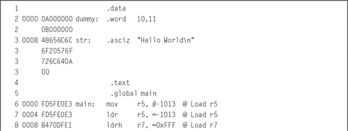
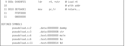
Line 8 shows the ldr pseudo-instruction being used to load a value that cannot be loaded using the mov instruction. The assembler generated a load half-word instruction using the program counter as the base register, and an offset to the location where the value is stored. The value is actually stored in a literal pool at the end of the text segment. The listing has three lines labeled 11. The first line 11 is an instruction. The remaining lines are the literal pool.
On line 9, the programmer used the ldr pseudo-instruction to request that the address of str be loaded into r4. The assembler created a storage location to hold the address of str, and generated a load word instruction using the program counter as the base register and an offset to the location where the address is stored. The address of str is actually stored in the text segment, on the third line 11.
3.6.2 Load Address
These pseudo instructions are used to load the address associated with a label:
adrl Load Address Long
They are more efficient than the ldr rx,=label instruction, because they are translated into one or two add or subtract operations, and do not require a load from memory. However, the address must be in the same section as the adr or adrl pseudo-instruction, so they cannot be used to load addresses of labels in the .data section.
Syntax
• The adr pseudo-instruction will be translated into one or two pc-relative add or sub instructions.
• The adrl pseudo-instruction will always be translated into two instructions. The second instruction may be a nop instruction.
• The label must be defined in the same file and section where these pseudo-instructions are used.
Operations

Examples

3.7 Chapter Summary
The ARM Instruction Set Architecture includes 17 registers and a four basic instruction types. This chapter explained the instructions used for
• moving data between memory and registers, and
• branching and calling subroutines.
The load and store operations are used to move data between memory and registers. The basic load and store operations, ldr and str, have a very powerful set of addressing modes. To facilitate moving multiple registers to or from memory, the ARM ISA provides the ldm and stm instructions, which each have several variants. The assembler provides two pseudo-instructions for loading addresses and immediate values.
The ARM processor provides only two types of branch instruction. The bl instruction is used to call subroutines (functions). The b instruction can be used to create loops and to create if-then-else constructs. The ability to append a condition to almost any instruction results in a very rich instruction set.
Exercises
3.1 Which registers hold the stack pointer, return address, and program counter?
3.2 Which is more efficient for loading a constant value, the ldr pseudo-instruction, or the mov instruction? Explain.
3.3 Which two variants of the Store Multiple instruction are used most often, and why?
3.4 The stm and ldm instructions include an optional ‘!’ after the address register. What does it do?
3.5 The following C statement declares an array of four integers, and initializes their values to 7, 3, 21, and 10, in that order.
(a) Write the equivalent in GNU ARM assembly.
(b) Write the ARM assembly instructions to load all four numbers into registers r3, r5, r6, and r9, respectively, using:
i. a single ldm instruction, and
ii. four ldr instructions.
3.6 What is the difference between a memory location and a CPU register?
3.7 How many registers are provided by the ARM Instruction Set Architecture?
3.8 Use ldm and stm to write a short sequence of ARM assembly language to copy 16 words of data from a source address to a destination address. Assume that the source address is already loaded in r0 and the destination address is already loaded in r1. You may use registers r2 through r5 to hold values as needed. Your code is allowed to modify r0 and/or r1.
3.9 Assume that x is an array of integers. Convert the following C statements into ARM assembly language.
(b) x[10] = x[0];
(c) x[9] = x[3];
3.10 Assume that x is an array of integers, and i and j are integers. Convert the following C statements into ARM assembly language.
(b) x[j] = x[i];
(c) x[i] = x[j*2];
3.11 What is the difference between the b instruction and the bl instruction? What is each used for?
3.12 What are the meanings of the following instructions?
(b) ldrlt
(c) bgt
(d) bne
(e) bge