Table of Contents for
Modern Assembly Language Programming with the ARM Processor
 Modern Assembly Language Programming with the ARM Processor
Published by
Newnes, 2016
Modern Assembly Language Programming with the ARM Processor
Published by
Newnes, 2016
- Modern Assembly Language Programming with the ARM Processor
- Cover image
- Title page
- Table of Contents
- Copyright
- List of Tables
- List of Figures
- List of Listings
- Preface
- Companion Website
- Acknowledgments
- Part I: Assembly as a Language
- Chapter 1: Introduction
- Chapter 2: GNU Assembly Syntax
- Chapter 3: Load/Store and Branch Instructions
- Chapter 4: Data Processing and Other Instructions
- Chapter 5: Structured Programming
- Chapter 6: Abstract Data Types
- Part II: Performance Mathematics
- Chapter 7: Integer Mathematics
- Chapter 8: Non-Integral Mathematics
- Chapter 9: The ARM Vector Floating Point Coprocessor
- Chapter 10: The ARM NEON Extensions
- 10.10 Multiplication and Division
- Part III: Accessing Devices
- Chapter 11: Devices
- Chapter 12: Pulse Modulation
- Chapter 13: Common System Devices
- Chapter 14: Running Without an Operating System
- Index
Data Processing and Other Instructions
Abstract
This chapter begins by explaining Operand2, which is used by most ARM data processing instructions to specify one of the source operands for the data processing operation. It explains all of the shift operations and how they can be combined with other data processing operations in a single instruction. It then explains each of the data processing instructions, giving a short example showing how they can be used. Short examples, relating the assembly instructions to C statements, are incorporated throughout the chapter. One of the examples shows how to construct a loop. After the data processing instructions are explained, the chapter covers the special instructions and pseudo-instructions.
Keywords
Operand2; Data processing; Shift; Loop; Comparison; Data movement; Three address instruction; Two address instruction
The ARM processor has approximately 25 data processing instructions. The exact number depends on the processor version. For example, older versions of the architecture did not have the six multiply instructions, and the Cortex M3 and newer processors have two division instructions. There are also a few special instructions that are used infrequently to perform operations that are not classified as load/store, branch, or data processing.
4.1 Data Processing Instructions
The data processing instructions operate only on CPU registers, so data must first be moved from memory into a register before processing can be performed. Most of these instructions use two source operands and one destination register. Each instruction performs one basic arithmetical or logical operation. The operations are grouped in the following categories:
• Logical Operations,
• Comparison Operations,
• Data Movement Operations,
• Status Register Operations,
• Multiplication Operations, and
• Division Operations.
4.1.1 Operand2
Most of the data processing instructions require the programmer to specify two source operands and one destination register for the result. Because three items must be specified for these instructions, they are known as three address instructions. The use of the word address in this case has nothing to do with memory addresses. The term three address instruction comes from earlier processor architectures that allow arithmetic operations to be performed with data that is stored in memory rather than registers. The first source operand specifies a register whose contents will be on the A bus in Fig. 3.1. The second source operand will be on the B bus and is referred to as Operand2. Operand2 can be any one of the following three things:
• a register (r0-r15) and a shift operation to modify it, or
• a 32-bit immediate value that can be constructed by shifting, rotating, and/or complementing an 8-bit value.
The options for Operand2 allow a great deal of flexibility. Many operations that would require two instructions on most processors can be performed using a single ARM instruction. Table 4.1 shows the mnemonics used for specifying shift operations, which we refer to as < shift_op >.
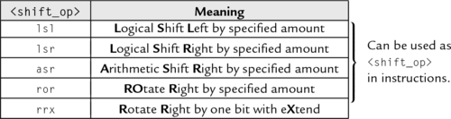
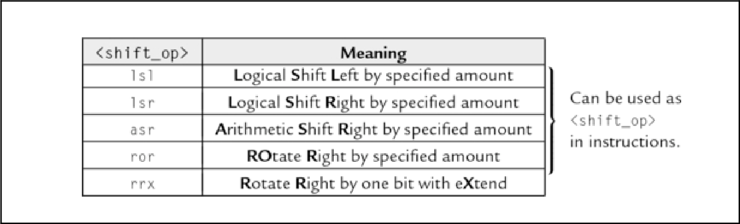
The lsl operation shifts each bit left by a specified amount n. Zero is shifted into the n least significant bits, and the most significant n bits are lost. The lsr operation shifts each bit right by a specified amount n. Zero is shifted into the n most significant bits, and the least significant n bits are lost. The asr operation shifts each bit right by a specified amount n. The n most significant bits become copies of the sign bit (bit 31), and the least significant n bits are lost. The ror operation rotates each bit right by a specified amount n. The n most significant bits become the least significant n bits. The RRX operation rotates one place to the right but the CPSR carry flag, C, is included. The carry flag and the register together create a 33 bit quantity to be rotated. The carry flag is rotated into the most significant bit of the register, and the least significant bit of the register is rotated into the carry flag. Table 4.2 shows all of the possible forms for Operand2.
Table 4.2
Formats for Operand2
| #<immediate|symbol> | A 32-bit immediate value that can be constructed from an 8 bit value |
| Rm | Any of the 16 registers r0-r15 |
| Rm, <shift_op> #<shift_imm> | The contents of a register shifted or rotated by an immediate amount between 0 and 31 |
| Rm, <shift_op> Rs | The contents of a register shifted or rotated by an amount specified by the contents of another register |
| Rm, rrx | The contents of a register rotated right by one bit through the carry flag |
4.1.2 Comparison Operations
These four comparison operations update the CPSR flags, but have no other effect:
cmn Compare Negative,
tst Test Bits, and
teq Test Equivalence.
They each perform an arithmetic operation, but the result of the operation is discarded. Only the CPSR carry flags are affected.
Syntax
• <op> is either cmp, cmn, tst, or teq.
• The optional <cond> can be any of the codes from Table 3.2 specifying conditional execution.
Operations
Examples

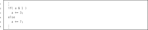
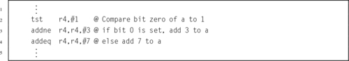
Example 4.1 shows how conditional execution and the test instruction can be used together to create an if-then-else structure. Note that in this case, the assembly code is more concise than the C code. That is not generally true.
4.1.3 Arithmetic Operations
There are six basic arithmetic operations:
adc Add with Carry,
sub Subtract,
sbc Subtract with Carry,
rsb Reverse Subtract, and
rsc Reverse Subtract with Carry.
All of them involve two 32-bit source operands and a destination register.
Syntax
• <op> is one of add, adc, sub, sbc, or rsb, or rsc.
• The optional s specifies whether or not the instruction should affect the bits in the CPSR.
• The optional <cond> can be any of the codes from Table 3.2 on page 59 specifying conditional execution.
Operations


Examples
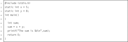
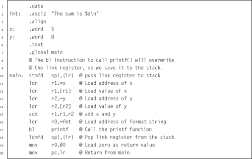
Example 4.2 shows a complete program for adding the contents of two statically allocated variables and printing the result. The printf () function expects to find the address of a string in r0. As it prints the string, it finds the \%d formatting command, which indicates that the value of an integer variable should be printed. It expects the variable to be stored in r1. Note that the variable sum does not need to be stored in memory. It is stored in r1, where printf () expects to find it.
Example 4.2
Adding the Contents of Two Variables
The following C program will add together two numbers stored in memory and print the result.
The equivalent ARM assembly program is as follows:
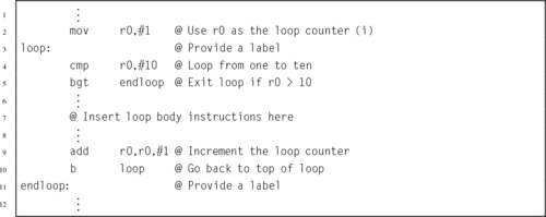
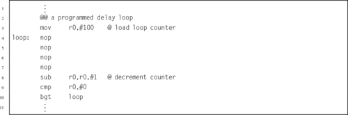
Example 4.3 shows how the compare, branch, and add instructions can be used to create a loop. There are basically three steps for creating a loop: allocating and initializing the loop variable, testing the loop variable, and modifying the loop variable. In general, any of the registers r0-r12 can be used to hold the loop variable. Section 5.4 introduces some considerations for choosing an appropriate register. For now, it is assumed that r0 is available for use as the loop variable for this example.
Example 4.3
Making a Loop
Suppose we want to implement a loop that is equivalent to the following C code:
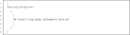
The loop can be written with the following ARM assembly code:
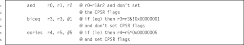
4.1.4 Logical Operations
There are five basic logical operations:
orr Bitwise OR,
eor Bitwise Exclusive OR,
orn Bitwise OR NOT, and
bic Bit Clear.
All of them involve two source operands and a destination register.
Syntax
• <op> is either and, eor, orr, orn, or bic.
• The optional s specifies whether or not the instruction should affect the bits in the CPSR.
• The optional <cond> can be any of the codes from Table 3.2 specifying conditional execution.
Operations


Examples
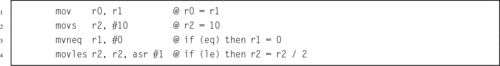
4.1.5 Data Movement Operations
The data movement operations copy data from one register to another:
mvn Move Not, and
movt Move Top.
The movt instruction copies 16 bits of data into the upper 16 bits of the destination register, without affecting the lower 16 bits. It is available on ARMv6T2 and newer processors.
Syntax
• The optional s specifies whether or not the instruction should affect the bits in the CPSR.
• The optional <cond> can be any of the codes from Table 3.2 specifying conditional execution.
Operations


Examples
4.1.6 Multiply Operations with 32-bit Results
These two instructions perform multiplication using two 32-bit registers to form a 32-bit result:
mla Multiply and Accumulate.
The mla instruction adds a third register to the result of the multiplication.
Syntax
• The optional s specifies whether or not the instruction should affect the bits in the CPSR.
• The optional <cond> can be any of the codes from Table 3.2 specifying conditional execution.
Operations


Examples
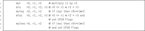
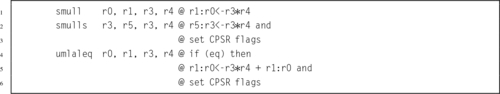
4.1.7 Multiply Operations with 64-bit Results
These instructions perform multiplication using two 32-bit registers to form a 64-bit result:
umull Unsigned Multiply Long,
smlal Signed Multiply and Accumulate Long, and
umlal Unsigned Multiply and Accumulate Long.
The smlal and umlal instructions add a 64-bit quantity to the result of the multiplication.
Syntax
• <type> must be either s for signed or u for unsigned.
• <op> must be either mul, or mla.
• The optional s specifies whether or not the instruction should affect the bits in the CPSR.
• The optional <cond> can be any of the codes from Table 3.2 specifying conditional execution.
Operations


Examples
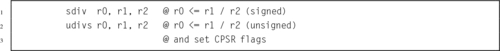
4.1.8 Division Operations
Some ARM processors have the following instructions to perform division:
udiv Unsigned Divide.
The divide operations are available on Cortex M3 and newer ARM processors. The processor used on the Raspberry Pi does not have these instructions. The Raspberry Pi 2 does have them.
Syntax
• <type> must be either s for signed or u for unsigned.
• The optional <cond> can be any of the codes from Table 3.2 specifying conditional execution.
• The optional s specifies whether or not the instruction should affect the bits in the CPSR.
Operations

Examples
4.2 Special Instructions
There are a few instructions that do not fit into any of the previous categories. They are used to request operating system services and access advanced CPU features.
4.2.1 Count Leading Zeros
This instruction counts the number of leading zeros in the operand register and stores the result in the destination register:
Syntax
• The optional <cond> can be any of the codes from Table 3.2 specifying conditional execution.
Operations

Example

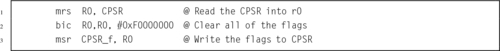
4.2.2 Accessing the CPSR and SPSR
These two instructions allow the programmer to access the status bits of the CPSR and SPSR:
mrs Move Status to Register, and
msr Move Register to Status.
The SPSR is covered in Section 14.1.
Syntax
• The optional < fields > is any combination of:
x extension field
s status field
f flags field
• The optional <cond> can be any of the codes from Table 3.2 specifying conditional execution.
Operations


Examples
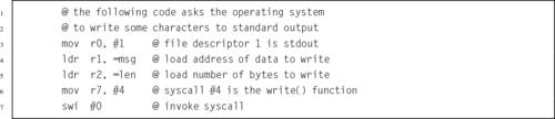
4.2.3 Software Interrupt
The following instruction allows a user program to perform a system call to request operating system services:
In Unix and Linux, the system calls are documented in the second section of the online manual. Each system call has a unique id number which is defined in the /usr/include/syscall.h file.
Syntax
• The <syscall_number> is encoded in the instruction. The operating system may examine it to determine which operating system service is being requested.
• In Linux, <syscall_number> is ignored. The system call number is passed in r7, and up to seven parameters are passed in r0-r6. No Linux system call requires more than seven parameters.
Operations
Example
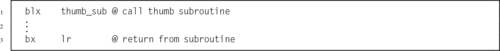
4.2.4 Thumb Mode
The ARM processor has an alternate mode where it executes a 16-bit instruction set known as Thumb. This instruction allows the programmer to change the processor mode and branch to Thumb code:
The thumb instruction set is sometimes more efficient than the full ARM instruction set, and may offer advantages on small systems.
Syntax
Operations


Example
4.3 Pseudo-Instructions
The assembler provides a small number of pseudo-instructions. From the perspective of the programmer, these instructions are indistinguishable from standard instructions. However, when the assembler encounters a pseudo-instruction, it may substitute a different instruction or generate a short sequence of machine instructions.
4.3.1 No Operation
This pseudo instruction does nothing, but takes one clock cycle to execute.
This is equivalent to a mov r0,r0 instruction.
Syntax
Operations
Examples
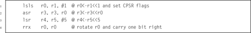
4.3.2 Shifts
These pseudo instructions are assembled into mov instructions with an appropriate shift of Operand2:
lsr Logical Shift Right,
asr Arithmetic Shift Right,
ror Rotate Right, and
rrx Rotate Right with eXtend.
Syntax
• <op> must be either lsl, lsr, asr, or ror.
• Rs is a register holding the shift amount. Only the least significant byte is used.
• shift must be between 1 and 32.
• If the optional s is specified, then the N and Z flags are updated according to the result, and the C flag is updated to the last bit shifted out.
• The optional <cond> can be any of the codes from Table 3.2 on page 59 specifying conditional execution.
Operations
| Name | Effect | Description |
| lsl |  | Shift Left |
| lsr |  | Shift Right |
| asr | | Shift Right with sign extend |
| rrx |  | Rotate Right with eXtend |
The rrx operation rotates one place to the right but the CPSR carry flag, C, is included. The carry flag and the register together create a 33-bit quantity to be rotated. The carry flag is rotated into the most significant bit of the register, and the least significant bit of the register is rotated into the carry flag.
Examples
4.4 Alphabetized List of ARM Instructions
This chapter and the previous one introduced the core set of ARM instructions. Most of these instructions were introduced with the very first ARM processors. There are approximately 50 additional instructions and pseudo instructions that were introduced with the ARMv6 and later versions of the architecture, or that only appear in specific versions of the ARM. There are also additional instructions available on systems that have the Vector Floating Point (VFP) coprocessor and/or the NEON extensions. The instructions introduced so far are:
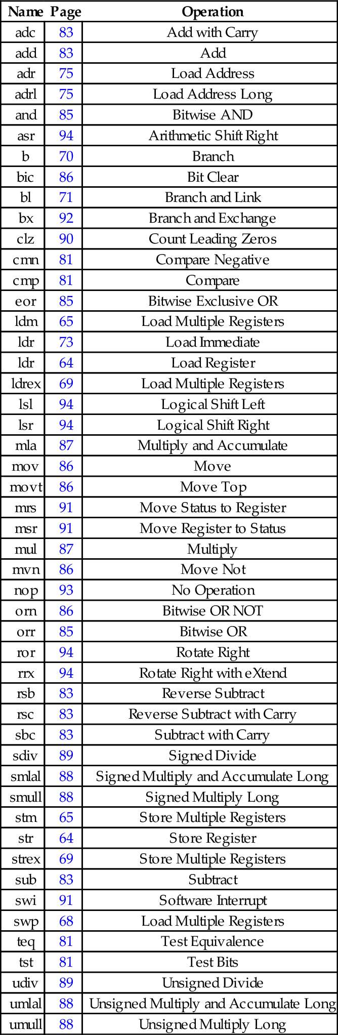
| Name | Page | Operation |
| adc | 83 | Add with Carry |
| add | 83 | Add |
| adr | 75 | Load Address |
| adrl | 75 | Load Address Long |
| and | 85 | Bitwise AND |
| asr | 94 | Arithmetic Shift Right |
| b | 70 | Branch |
| bic | 86 | Bit Clear |
| bl | 71 | Branch and Link |
| bx | 92 | Branch and Exchange |
| clz | 90 | Count Leading Zeros |
| cmn | 81 | Compare Negative |
| cmp | 81 | Compare |
| eor | 85 | Bitwise Exclusive OR |
| ldm | 65 | Load Multiple Registers |
| ldr | 73 | Load Immediate |
| ldr | 64 | Load Register |
| ldrex | 69 | Load Multiple Registers |
| lsl | 94 | Logical Shift Left |
| lsr | 94 | Logical Shift Right |
| mla | 87 | Multiply and Accumulate |
| mov | 86 | Move |
| movt | 86 | Move Top |
| mrs | 91 | Move Status to Register |
| msr | 91 | Move Register to Status |
| mul | 87 | Multiply |
| mvn | 86 | Move Not |
| nop | 93 | No Operation |
| orn | 86 | Bitwise OR NOT |
| orr | 85 | Bitwise OR |
| ror | 94 | Rotate Right |
| rrx | 94 | Rotate Right with eXtend |
| rsb | 83 | Reverse Subtract |
| rsc | 83 | Reverse Subtract with Carry |
| sbc | 83 | Subtract with Carry |
| sdiv | 89 | Signed Divide |
| smlal | 88 | Signed Multiply and Accumulate Long |
| smull | 88 | Signed Multiply Long |
| stm | 65 | Store Multiple Registers |
| str | 64 | Store Register |
| strex | 69 | Store Multiple Registers |
| sub | 83 | Subtract |
| swi | 91 | Software Interrupt |
| swp | 68 | Load Multiple Registers |
| teq | 81 | Test Equivalence |
| tst | 81 | Test Bits |
| udiv | 89 | Unsigned Divide |
| umlal | 88 | Unsigned Multiply and Accumulate Long |
| umull | 88 | Unsigned Multiply Long |
4.5 Chapter Summary
The ARM Instruction Set Architecture includes 17 registers and four basic instruction types. This chapter introduced the instructions used for
• moving data from one register to another,
• performing computational operations with two source operands and one destination register,
• multiplication and division,
• performing comparisons, and
• performing special operations.
Most of the data processing instructions are three address instructions, because they involve two source operands and produce one result. For most instructions, the second source operand can be a register, a rotated or shifted register, or an immediate value. This flexibility results in a relatively powerful assembly language. In addition, almost all instructions can be executed conditionally, which, if used properly, results in very efficient and compact code.
Exercises
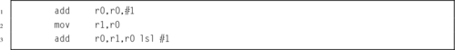
4.1 If r0 initially contains 1, what will it contain after the third instruction in the sequence below?
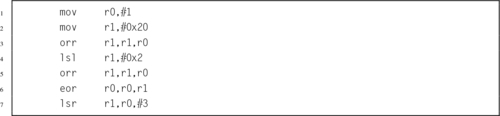
4.2 What will r0 and r1 contain after each of the following instructions? Give your answers in base 10.
4.3 What is the difference between lsr and asr?
4.4 Write the ARM assembly code to load the numbers stored in num1 and num2, add them together, and store the result in numsum. Use only r0 and r1.
4.5 Given the following variable definitions:

where you do not know the values of x and y, write a short sequence of ARM assembly instructions to load the two numbers, compare them, and move the largest number into register r0.
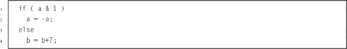
4.6 Assuming that a is stored in register r0 and b is stored in register r1, show the ARM assembly code that is equivalent to the following C code.
4.7 Without using the mul instruction, give the instructions to multiply r3 by the following constants, leaving the result in r0. You may also use r1 and r2 to hold temporary results, and you do not need to preserve the original contents of r3.
(b) 100
(c) 575
(d) 123
4.8 Assume that r0 holds the least significant 32 bits of a 64-bit integer a, and r1 holds the most significant 32 bits of a. Likewise, r2 holds the least significant 32 bits of a 64-bit integer b, and r3 holds the most significant 32 bits of b. Show the shortest instruction sequences necessary to:
(a) compare a to b, setting the CPSR flags,
(b) shift a left by one bit, storing the result in b,
(c) add b to a, and
(d) subtract b from a.
4.9 Write a loop to count the number of bits in r0 that are set to 1. Use any other registers that are necessary.
4.10 The C standard library provides the open() function, which is documented in the second section of the Linux manual pages. This function is a very small “wrapper” to allow C programmers to access the open() system call. Assembly programmers can access the system call directly. In ARM Linux, the system call number for open() is 5. The values for flag constants used with open() are defined in
Write the ARM assembly instructions and directives necessary to make a Linux system call to open a file named input.txt for reading, without using the C standard library. In other words, write the assembly equivalent to: open(”input.txt”,O˙RDONLY); using the swi instruction.