Table of Contents for
Modern Assembly Language Programming with the ARM Processor
 Modern Assembly Language Programming with the ARM Processor
Published by
Newnes, 2016
Modern Assembly Language Programming with the ARM Processor
Published by
Newnes, 2016
- Modern Assembly Language Programming with the ARM Processor
- Cover image
- Title page
- Table of Contents
- Copyright
- List of Tables
- List of Figures
- List of Listings
- Preface
- Companion Website
- Acknowledgments
- Part I: Assembly as a Language
- Chapter 1: Introduction
- Chapter 2: GNU Assembly Syntax
- Chapter 3: Load/Store and Branch Instructions
- Chapter 4: Data Processing and Other Instructions
- Chapter 5: Structured Programming
- Chapter 6: Abstract Data Types
- Part II: Performance Mathematics
- Chapter 7: Integer Mathematics
- Chapter 8: Non-Integral Mathematics
- Chapter 9: The ARM Vector Floating Point Coprocessor
- Chapter 10: The ARM NEON Extensions
- 10.10 Multiplication and Division
- Part III: Accessing Devices
- Chapter 11: Devices
- Chapter 12: Pulse Modulation
- Chapter 13: Common System Devices
- Chapter 14: Running Without an Operating System
- Index
Non-Integral Mathematics
Abstract
This chapter starts by demonstrating how to convert fractional numbers to radix notation in any base. It then presents a theorem that can be used to determine in which bases a given fraction will terminate rather than repeating. That theorem is then used to explain why some base ten fractional numbers cannot be represented in binary with a finite number of bits. Next fixed-point numbers are introduced. The rules for addition, subtraction, multiplication, and division are given. Division by a constant is explained in terms of fixed-point mathematics. Next, the IEEE floating point formats are explained. The chapter ends with an example showing how fixed-point mathematics can be used to write functions for sine and cosine which give better precision and higher performance than the functions provided by GCC.
Keywords
Fixed point; Radix point; Non-terminating repeating fraction; S/U notation; Q notation; Floating point; Performance
Chapter 7 introduced methods for performing computation using integers. Although many problems can be solved using only integers, it is often necessary (or at least more convenient) to perform computation using real numbers or even complex numbers. For our purposes, a non-integral number is any number that is not an integer. Many systems are only capable of performing computation using binary integers, and have no hardware support for non-integral calculations. In this chapter, we will examine methods for performing non-integral calculations using only integer operations.
8.1 Base Conversion of Fractional Numbers
Section 1.3.2 explained how to convert integers in a given base into any other base. We will now extend the methods to convert fractional values. A fractional number can be viewed as consisting of an integer part, a radix point, and a fractional part. In base 10, the radix point is also known as the decimal point. In base 2, it is called the binimal point. For base 16, it is the heximal point, and in base 8 it is an octimal point. The term radix point is used as a general term for a location that divides a number into integer and fractional parts, without specifying the base.
8.1.1 Arbitrary Base to Decimal
The procedure for converting fractions from a given base b into base ten is very similar to the procedure used for integers. The only difference is that the digit to the left of the radix point is weighted by b0 and the exponents become increasingly negative for each digit right of the radix point. The basic procedure is the same for any base b. For example, the value 101.01012 can be converted to base ten by expanding it as follows:
Likewise, the hexadecimal fraction 4F2.9A0 can be converted to base ten by expanding it as follows:
8.1.2 Decimal to Arbitrary Base
When converting from base ten into another base, the integer and fractional parts are treated separately. The base conversion for the integer part is performed in exactly the same way as in Section 1.3.2, using repeated division by the base b. The fractional part is converted using repeated multiplication. For example, to convert the decimal value 5.687510 to a binary representation:
1. Convert the integer portion, 510 into its binary equivalent, 1012.
2. Multiply the decimal fraction by two. The integer part of the result is the first binary digit to the right of the radix point.
Because x = 0.6875 × 2 = 1.375, the first binary digit to the right of the point is a 1. So far, we have 5.62510 = 101.12
3. Multiply the fractional part of x by 2 once again.
Because x = 0.375 × 2 = 0.75, the second binary digit to the right of the point is a 0. So far, we have 5.62510 = 101.102
4. Multiply the fractional part of x by 2 once again.
Because x = 0.75 × 2 = 1.50, the third binary digit to the right of the point is a 1. So now we have 5.625 = 101.101
5. Multiply the fractional part of x by 2 once again.
Because x = 0.5 × 2 = 1.00, the fourth binary digit to the right of the point is a 1. So now we have 5.625 = 101.1011
6. Since the fractional part is now zero, we know that all remaining digits will be zero.
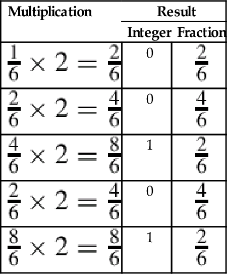
The procedure for obtaining the fractional part can be accomplished easily using a tabular method, as shown below:
| Operation | Result | |
| Integer | Fraction | |
| 0.6875 × 2 = 1.375 | 1 | 0.375 |
| 0.375 × 2 = 0.75 | 0 | 0.75 |
| 0.75 × 2 = 1.5 | 1 | 0.5 |
| 0.5 × 2 = 1.0 | 1 | 0.0 |
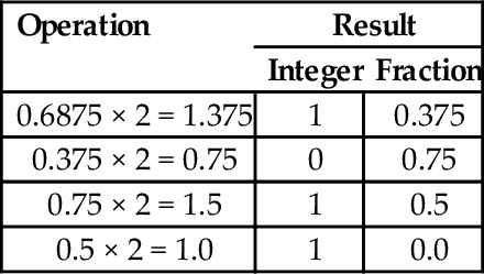
Putting it all together, 5.687510 = 101.10112. After converting a fraction from base 10 into another base, the result should be verified by converting back into base 10. The results from the previous example can be expanded as follows:
Converting decimal fractions to base sixteen is accomplished in a very similar manner. To convert 842.23437510 into base 16, we first convert the integer portion by repeatedly dividing by 16 to yield 34A. We then repeatedly multiply the fractional part, extracting the integer portion of the result each time as shown in the table below:
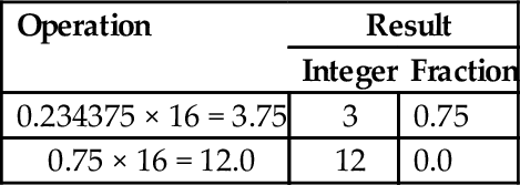
In the second line, the integer part is 12, which must be replaced with a hexadecimal digit. The hexadecimal digit for 1210 is C, so the fractional part is 3C. Therefore, 842.23437510 =34A.3C16 The result is verified by converting it back into base 10 as follows:
Bases that are powers-of-two
Converting fractional values between binary, hexadecimal, and octal can be accomplished in the same manner as with integer values. However, care must be taken to align the radix point properly. As with integers, converting from hexadecimal or octal to binary is accomplished by replacing each hex or octal digit with the corresponding binary digits from the appropriate table shown in Fig. 1.3.
For example, to convert 5AC.43B16 to binary, we just replace “5” with “0101,” replace “A” with “1010,” replace “C” with “1100,” replace “4” with “0100,” replace “3” with “0011,” replace “B” with “1011,” So, using the table, we can immediately see that 5AC.43B16 = 010110101100.0100001110112. This method works exactly the same way for converting from octal to binary, except that it uses the table on the right side of Fig. 1.3.
Converting fractional numbers from binary to hexadecimal or octal is also very easy when using the tables. The procedure is to split the binary string into groups of bits, working outwards from the radix point, then replace each group with its hexadecimal or octal equivalent. For example, to convert 01110010.10101112 to hexadecimal, just divide the number into groups of four bits, starting at the radix point and working outwards in both directions. It may be necessary to pad with zeroes to make a complete group on the left or right, or both. Our example is grouped as follows: |0000|0111|0010.1010|1110|2. Now each group of four bits is converted to hexadecimal by looking up the corresponding hex digit in the table on the left side of Fig. 1.3. This yields 072.AE16. For octal, the binary number would be grouped as follows: |001|110|010.101|011|100|2. Now each group of three bits is converted to octal by looking up the corresponding digit in the table on the right side of Fig. 1.3. This yields 162.5348.
8.2 Fractions and Bases
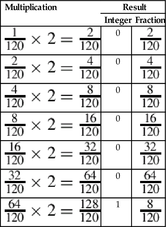
One interesting phenomenon that is often encountered is that fractions which terminate in one base may become non-terminating, repeating fractions in another base. For example, the binary representation of the decimal fraction  is a repeating fraction, as shown in Example 8.1. The resulting fractional part from the last step performed is exactly the same as in the second step. Therefore, the sequence will repeat. If we continue, we will repeat the sequence of steps 2–5 forever. Hence, the final binary representation will be:
Because of this phenomenon, it is impossible to exactly represent 1.1010 (and many other fractional quantities) as a binary fraction in a finite number of bits.
The fact that some base 10 fractions cannot be exactly represented in binary has lead to many subtle software bugs and round-off errors, when programmers attempt to work with currency (and other quantities) as real-valued numbers. In this section, we explore the idea that the representation problem can be avoided by working in some base other than base 2. If that is the case, then we can simply build hardware (or software) to work in that base, and will be able to represent any fractional value precisely using a finite number of digits. For brevity, we will refer to a binary fractional quantity as a binimal and a decimal fractional quantity as a decimal. We would like to know whether there are more non-terminating decimals than binimals, more non-terminating binimals than decimals, or neither. Since there are an infinite number of non-terminating decimals and an infinite number of non-terminating binimals, we could be tempted to conclude that they are equal. However, that is an oversimplification. If we ask the question differently, we can discover some important information. A better way to ask the question is as follows:
Question: Is the set of terminating decimals a subset of the set of terminating binimals, or vice versa, or neither?
We start by introducing a lemma which can be used to predict whether or not a terminating fraction in one base will terminate in another base. We introduce the notation x|y (read as “x divides y”) to indicate that y can be evenly divided by x.
Lemma 8.2.1
If x, 0 < x < 1, terminates in some base B (a product of primes), then  , and
, and  , where the pi are the prime factors of B.
Proof
Let , and , where the pi are the prime factors of B. Then  , where kmax = max(k1,k2,…kn), so
  terminates after kmax or fewer divisions.
Let terminate after k divisions. Then Dx|Nx × Bk. Since Dx does not evenly divide Nx, Dx must be composed of some combination of the prime factors of B. Thus, Dx can be expressed as  .
.
Proof
Let b be a terminating binimal. Then, by Lemma 8.2.1,  , such that Db = 2k, for some k ≥ 0. Therefore, Db = 2k5m, for some k, m > 0, and again by the Lemma, b is also a terminating decimal.
Proof
Let d be a terminating decimal such that  , where Dd = 2k5m. If m > 0, then by the Lemma, d is a non-terminating binimal.
Answer: The set of terminating binimals is a subset of the set of terminating decimals, but the set of terminating decimals is not a subset of the set of terminating binimals.
Implications
Theorem 8.2.1 implies that any binary fraction can be expressed exactly as a decimal fraction, but Theorem 8.2.2 implies that there are decimal fractions which cannot be expressed exactly in binary. Every fraction (when expressed in lowest terms) which has a non-zero power of five in its denominator cannot be represented in binary with a finite number of bits. Another implication is that some fractions cannot be expressed exactly in either binary or decimal. For example, let B = 30 = 2 * 3 * 5. Then any number with denominator  terminates in base 30. However if k2≠0, then the fraction will terminate in neither base two nor base ten, because three is not a prime factor of ten or two.
Another implication of the theorem is that the more prime factors we have in our base, the more fractions we can express exactly. For instance, the smallest base that has two, three, and five as prime factors is base 30. Using that base, we can exactly express fractions in radix notation that cannot be expressed in base ten or in base two with a finite number of digits. For example, in base 30, the fraction  will terminate after one division since 15 = 3151. To see what the number will look like, let us extend the hexadecimal system of using letters to represent digits beyond 9. So we get this chart for base 30:
Since  , the fraction can be expressed precisely as 0.M30. Likewise, the fraction
  is
is  but terminates in base 30. Since 45 = 3351, this number will have three or fewer digits following the radix point. To compute the value, we will have to raise it to higher terms. Using 302 as the denominator gives us:

Now we can convert it to base 30 by repeated division.  with remainder 20. Since 20 < 30, we cannot divide again. Therefore, in base 30 is 0.8K.
Although base 30 can represent all fractions that can be expressed in bases two and ten, there are still fractions that cannot be represented in base 30. For example,  has the prime factor seven in its denominator, and therefore will only terminate in bases were seven is a prime factor of the base. The fraction will terminate in base 7, base 14, base 21, base 42 and many others, but not in base 30. Since there are an infinite number of primes, no number system is immune from this problem. No matter what base the computer works in, there are fractions that cannot be expressed exactly with a finite number of digits. Therefore, it is incumbent upon programmers and hardware designers to be aware of round-off errors and take appropriate steps to minimize their effects.
For example, there is no reason why the hardware clocks in a computer should work in base ten. They can be manufactured to measure time in base two. Instead of counting seconds in tenths, hundredths or thousandths, they could be calibrated to measure in fourths, eighths, sixteenths, 1024ths, etc. This would eliminate the round-off error problem in keeping track of time.
8.3 Fixed-Point Numbers
As shown in the previous section, given a finite number of bits, a computer can only approximately represent non-integral numbers. It is often necessary to accept that limitation and perform computations involving approximate values. With due care and diligence, the results will be accurate within some acceptable error tolerance. One way to deal with real-valued numbers is to simply treat the data as fixed- point numbers. Fixed-point numbers are treated as integers, but the programmer must keep track of the radix point during each operation. We will present a systematic approach to designing fixed-point calculations.
When using fixed-point arithmetic, the programmer needs a convenient way to describe the numbers that are being used. Most languages have standard data types for integers and floating point numbers, but very few have support for fixed-point numbers. Notable exceptions include PL/1 and Ada, which provide support for fixed-point binary and fixed-point decimal numbers. We will focus on fixed-point binary, but the techniques presented can also be applied to fixed-point numbers in any base.
8.3.1 Interpreting Fixed-Point Numbers
Each fixed-point binary number has three important parameters that describe it:
1. whether the number is signed or unsigned,
2. the position of the radix point in relation to the right side of the sign bit (for signed numbers) or the position of the radix point in relation to the most significant bit (for unsigned numbers), and
3. the number of fractional bits stored.
Unsigned fixed-point numbers will be specified as U(i,f), where i is the position of the radix point in relation to the left side of the most significant bit, and f is the number of bits stored in the fractional part.
For example, U(10,6) indicates that there are six bits of precision in the fractional part of the number, and the radix point is ten bits to the right of the most significant bit stored. The layout for this number is shown graphically as:
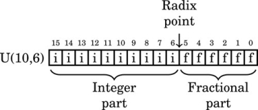
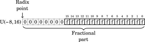
where i is an integer bit and f is a fractional bit. Very small numbers with no integer part may have a negative i. For example, U(−8,16) specifies an unsigned number with no integer part, eight leading zero bits which are not actually stored, and 16 bits of fractional precision. The layout for this number is shown graphically as:
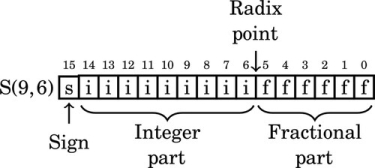
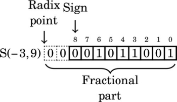
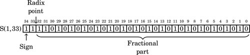
Likewise, signed fixed-point numbers will be specified using the following notation: S(i,f), where i is the position of the radix point in relation to the right side of the sign bit, and f is the number of fractional bits stored. As with integer two’s-complement notation, the sign bit is always the leftmost bit stored. For example, S(9,6) indicates that there are six bits in the fractional part of the number, and the radix point is nine bits to the right of the sign bit. The layout for this number is shown graphically as:
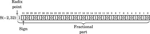
where i is an integer bit and f is a fractional bit. Very small numbers with no integer part may have a negative i. For example, S(−7,16) specifies a signed number with no integer part, six leading sign bits which are not actually stored, a sign bit that is stored and 15 bits of fraction. The layout for this number is shown graphically as:
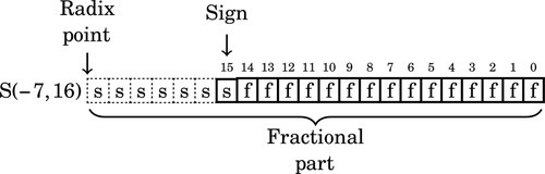
Note that the “hidden” bits in a signed number are assumed to be copies of the sign bit, while the “hidden” bits in an unsigned number are assumed to be zero.
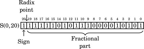
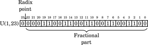
The following figure shows an unsigned fixed-point number with seven bits in the integer part and nine bits in the fractional part. It is a U(7,9) number. Note that the total number of bits is 7 + 9 = 16
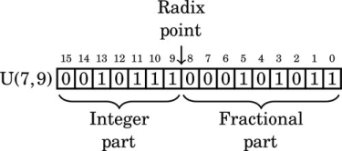
The value of this number in base 10 can be computed by summing the values of each non-zero bit as follows:
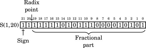
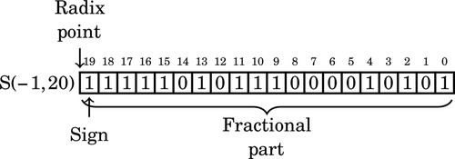
Likewise, the following figure shows a signed fixed-point number with nine bits in the integer part and six bits in the fractional part. It is as S(9,6) number. Note that the total number of bits is 9 + 6 + 1 = 16.
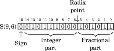
The value of this number in base 10 can be computed by summing the values of each non-zero bit as follows:
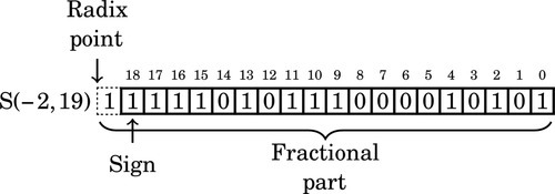
Note that in the above two examples, the pattern of bits are identical. The value of a number depends upon how it is interpreted. The notation that we have introduced allows us to easily specify exactly how a number is to be interpreted. For signed values, if the first bit is non-zero, then the two’s complement should be taken before the number is evaluated. For example, the following figure shows an S(8,7) number that has a negative value.
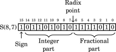
The value of this number in base 10 can be computed by taking the two’s complement, summing the values of the non-zero bits, and adding a negative sign to the result. The two’s complement of 1011010101111010 is 0100101010000101 + 1 = 0100101010000110. The value of this number is:
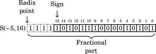
For a final example we will interpret this bit pattern as an S(−5,16). In that format, the layout is:

The value of this number in base ten can be computed by taking the two’s complement, summing the values of the non-zero bits, and adding a negative sign to the result. The two’s complement is:
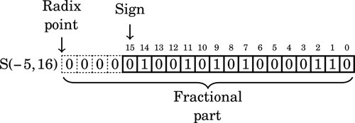
The value of this number interpreted as an S(−5,16) is:

8.3.2 Q Notation
Fixed-point number formats can also be represented using Q notation, which was developed by Texas Instruments. Q notation is equivalent to the S/U format used in this book, except that the integer portion is not always fully specified. In general, Q formats are specified as Qm, n where m is the number of integer bits, and n is the number of fractional bits. If a fixed word size w is being used then m may be omitted, and is assumed to be w − n. For example, a Q10 number has 10 fractional bits, and the number of integer bits is not specified, but is assumed to be the number of bits required to complete a word of data. A Q2,4 number has two integer bits and four fractional bits in a 6-bit word. There are two conflicting conventions for dealing with the sign bit. In one convention, the sign bit is included as part of m, and in the other convention, it is not. When using Q notation, it is important to state which convention is being used. Additionally, a U may be prefixed to indicate an unsigned value. For example UQ8.8 is equivalent to U(8,8), and Q7,9 is equivalent to S(7,9).
8.3.3 Properties of Fixed-Point Numbers
Once the decision has been made to use fixed-point calculations, the programmer must make some decisions about the specific representation of each fixed-point variable. The combination of size and radix will affect several properties of the numbers, including:
Precision: the maximum number of non-zero bits representable,
Resolution: the smallest non-zero magnitude representable,
Accuracy: the magnitude of the maximum difference between a true real value and its approximate representation,
Range: the difference between the largest and smallest number that can be represented, and
Dynamic range: the ratio of the maximum absolute value to the minimum positive absolute value representable.
Given a number specified using the notation introduced previously, we can determine its properties. For example, an S(9,6) number has the following properties:
Resolution: R = 2−6 = 0.015625
Accuracy: 
Range: Minimum value is 1000000000.000000 = −512 Maximum value is 0111111111.111111 = 1023.9921875 Range is G = 1023.9921875 + 512 = 1535.9921875
Dynamic range: For a signed fixed-point rational representation, S(i,f), the dynamic range is
Therefore, the dynamic range of an S(9,6) is 216 = 65536.
Being aware of these properties, the programmer can select fixed-point representations that fit the task that they are trying to solve. This allows the programmer to strive for very efficient code by using the smallest fixed-point representation possible, while still guaranteeing that the results of computations will be within some limits for error tolerance.
8.4 Fixed-Point Operations
Fixed-point numbers are actually stored as integers, and all of the integer mathematical operations can be used. However, some care must be taken to track the radix point at each stage of the computation. The advantages of fixed-point calculations are that the operations are very fast and can be performed on any computer, even if it does not have special hardware support for non-integral numbers.
8.4.1 Fixed-Point Addition and Subtraction
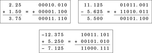
Fixed-point addition and subtraction work exactly like their integer counterparts. Fig. 8.1 gives some examples of fixed-point addition with signed numbers. Note that in each case, the numbers are aligned so that they have the same number of bits in their fractional part. This requirement is the only difference between integer and fixed-point addition. In fact, integer arithmetic is just fixed-point arithmetic with no bits in the fractional part. The arithmetic that was covered in Chapter 7 was fixed-point arithmetic using only S(i,0) and U(i,0) numbers. Now we are simply extending our knowledge to deal with numbers where f≠0. There are some rules which must be followed to ensure that the results are correct. The rules for subtraction are the same as the rules for addition. Since we are using two’s complement math, subtraction is performed using addition.
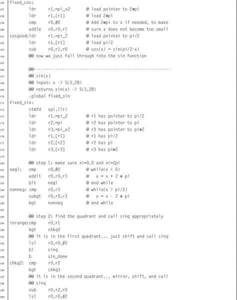
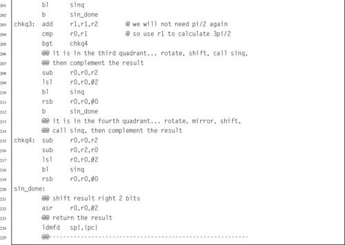
Suppose we want to add an S(7,8) number to an S(7,4) number. The radix points are at different locations, so we cannot simply add them. Instead, we must shift one of the numbers, changing its format, until the radix points are aligned. The choice of which one to shift depends on what format we desire for the result. If we desire eight bits of fraction in our result, then we would shift the S(7,4) left by four bits, converting it into an S(7,8). With the radix points aligned, we simply use an integer addition operation to add the two numbers. The result will have it’s radix point in the same location as the two numbers being added.
8.4.2 Fixed Point Multiplication
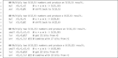
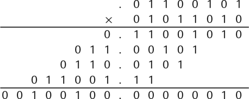
Recall that the result of multiplying an n bit number by an m bit number is an n + m bit number. In the case of fixed-point numbers, the size of the fractional part of the result is the sum of the number of fractional bits of each number, and the total size of the result is the sum of the total number of bits in each number. Consider the following example where two U(5,3) numbers are multiplied together:
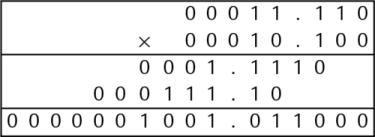
The result is a U(10,6) number. The number of bits in the result is the sum of all of the bits of the multiplicand and the multiplier. The number of fractional bits in the result is the sum of the number of fractional bits in the multiplicand and the multiplier. There are three simple rules to predict the resulting format when multiplying any two fixed-point numbers.
Unsigned Multiplication The result of multiplying two unsigned numbers U(i1,f1) and U(i2,f2) is a U(i1 + i2,f1 + f2) number.
Mixed Multiplication The result of multiplying a signed number S(i1,f1) and an unsigned number U(i2,f2) is an S(i1 + i2,f1 + f2) number.
Signed Multiplication The result of multiplying two signed numbers S(i1,f1) and S(i2,f2) is an S(i1 + i2 + 1,f1 + f2) number.
Note that this rule works for integers as well as fixed-point numbers, since integers are really fixed-point numbers with f = 0. If the programmer desires a particular format for the result, then the multiply is followed by an appropriate shift.
Listing 8.1 gives some examples of fixed-point multiplication using the ARM multiply instructions. In each case, the result is shifted to produce the desired format. It is the responsibility of the programmer to know what type of fixed-point number is produced after each multiplication and to adjust the result by shifting if necessary.
8.4.3 Fixed Point Division
Derivation of the rule for determining the format of the result of division is more complicated than the one for multiplication. We will first consider only unsigned division of a dividend with format U(i1,f1) by a divisor with format U(i2,f2).
Results of fixed point division
Consider the results of dividing two fixed-point numbers, using integer operations with limited precision. The value of the least significant bit of the dividend N is  and the value of the least significant bit of the divisor D is
  . In order to perform the division using integer operations, it is necessary to multiply N by
  and multiply D by
  so that both numbers are integers. Therefore, the division operation can be written as:
Note that no multiplication is actually performed. Instead, the programmer mentally shifts the radix point of the divisor and dividend, then computes the radix point of the result. For example, given two U(5,3) numbers, the division operation is accomplished by converting them both to integers, performing the division, then computing the location radix point:
Note that the result is an integer. If the programmer wants to have some fractional bits in the result, then the dividend must be shifted to the left before the division is performed.
If the programmer wants to have fq fractional bits in the quotient, then the amount that the dividend must be shifted can easily be computed as
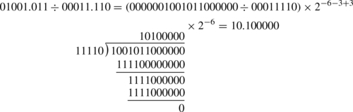
For example, suppose the programmer wants to divide 01001.011 stored as a U(28,3) by 00011.110 which is also stored as a U(28,3), and wishes to have six fractional bits in the result. The programmer would first shift 01001.011 to the left by six bits, then perform the division and compute the position of the radix in the result as shown:
Since the divisor may be between zero and one, the quotient may actually require more integer bits than there are in the dividend. Consider that the largest possible value of the dividend is  , and the smallest positive value for the divisor is
  . Therefore, the maximum quotient is given by:

Taking the limit of the previous equation,
provides the following bound on how many bits are required in the integer part of the quotient:

Therefore, in the worst case, the quotient will require i1 + f2 integer bits. For example, if we divide a U(3,5), a = 111.11111 = 7.9687510, by a U(5,3), b = 00000.001 = 0.12510, we end up with a U(6,2)q = 111111.11 = 63.7510.
The same thought process can be used to determine the results for signed division as well as mixed division between signed and unsigned numbers. The results can be reduced to the following three rules:
Unsigned Division The result of dividing an unsigned fixed-point number U(i1,f1) by an unsigned number U(i2,f2) is a U(i1 + f2,f1 − f2) number.
Mixed Division The result of dividing two fixed-point numbers where one of them is signed and the other is unsigned is an S(i1 + f2,f1 − f2) number.
Signed Division The result of dividing two signed fixed-point numbers is an S(i1 + f2 + 1,f1 − f2) number.
Consider the results when a U(2,3), a = 00000.001 = 0.12510 is divided by a U(4,1), b = 1000.0 = 8.010. The quotient is q = 0.000001, which requires six bits in the fractional part. However, if we simply perform the division, then according to the rules shown above, the result will be a U(8,−2). There is no such thing as a U(8,−2), so the result is meaningless.
When f2 > f1, blindly applying the rules will result in a negative fractional part. To avoid this, the dividend can be shifted left so that it has at least as many fractional bits as the divisor. This leads to the following rule: If f2 > f1 then convert the divisor to an S(i1,x), where x ≥ f2, then apply the appropriate rule. For example, dividing an S(5,2) by a U(3,12) would result in an S(17,−10). But shifting the S(5,2) 16 bits to the left will result in an S(5,18), and dividing that by a U(3,12) will result in an S(17,6).
Maintaining precision
Recall that integer division produces a result and a remainder. In order to maintain precision, it is necessary to perform the integer division operation in such a way that all of the significant bits are in the result and only insignificant bits are left in the remainder. The easiest way to accomplish this is by shifting the dividend to the left before the division is performed.
To find a rule for determining the shift necessary to maintain full precision in the quotient, consider the worst case. The minimum positive value of the dividend is  and the largest positive value for the divisor is
  . Therefore, the minimum positive quotient is given by:
Therefore, in the worst case, the quotient will require i2 + f1 fractional bits to maintain precision. However, fewer bits can be reserved if full precision is not required.
Recall that the least significant bit of the quotient will be  . Shifting the dividend left by i2 + f2 bits will convert it into a U(i1,i2 + f1 + f2). Using the rule above, when it is divided by a U(i2,f2), the result is a U(i1 + f2,i2 + f1). This is the minimum size which is guaranteed to preserve all bits of precision. The general method for performing fixed-point division while maintaining maximum precision is as follows:
1. shift the dividend left by i2 + f2, then
2. perform integer division.
The result will be a U(i1 + f2,i2 + f1) for unsigned division, or an S(i1 + f2 + 1,i2 + f1) for signed division. The result for mixed division is left as an exercise for the student.
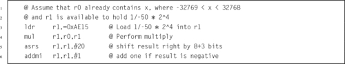
8.4.4 Division by a Constant
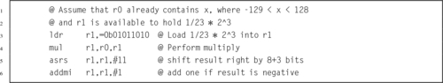
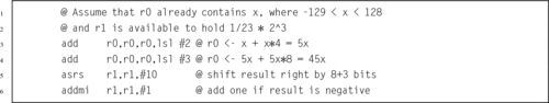
Section 7.3.3 introduced the idea of converting division by a constant into multiplication by the reciprocal of that constant. In that section it was shown that by pre-multiplying the reciprocal by a power of two (a shift operation), then dividing the final result by the same power of two (a shift operation), division by a constant could be performed using only integer operations with a more efficient multiply replacing the (usually) very slow divide.
This section presents an alternate way to achieve the same results, by treating division by an integer constant as an application of fixed-point multiplication. Again, the integer constant divisor is converted into its reciprocal, but this time the process is considered from the viewpoint of fixed-point mathematics. Both methods will achieve exactly the same results, but some people tend to grasp the fixed-point approach better than the purely integer approach.
When writing code to divide by a constant, the programmer must strive to achieve the largest number of significant bits possible, while using the shortest (and most efficient) representation possible. On modern computers, this usually means using 32-bit integers and integer multiply operations which produce 64-bit results. That would be extremely tedious to show in a textbook, so the principals will be demonstrated here using 8-bit integers and an integer multiply which produces a 16-bit result.
Division by constant 23
Suppose we want efficient code to calculate x ÷ 23 using only 8-bit signed integer multiplication. The reciprocal of 23, in binary, is
If we store R as an S(1,11), it would look like this:
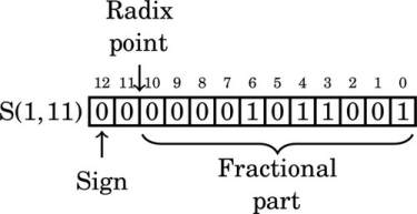
Note that in this format, the reciprocal of 23 has five leading zeros. We can store R in eight bits by shifting it left to remove some of the leading zeros. Each shift to the left changes the format of R. After removing the first leading zero bit, we have:
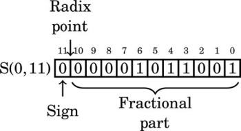
After removing the second leading zero bit, we have:
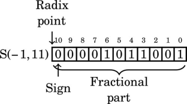
After removing the third leading zero bit, we have:
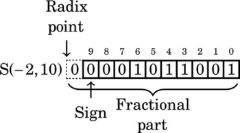
Note that the number in the previous format has a “hidden” bit between the radix point and the sign bit. That bit is not actually stored, but is assumed to be identical to the sign bit. Removing the fourth leading zero produces:
The number in the previous format has two “hidden” bits between the radix point and the sign bit. Those bits are not actually stored, but are assumed to be identical to the sign bit. Removing the fifth leading zero produces:
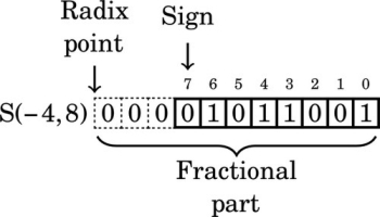
We can only remove five leading zero bits, because removing one more would change the sign bit from 0 to 1, resulting in a completely different number. Note that the final format has three “hidden” bits between the radix point and the sign bit. These bits are all copies of the sign bit. It is an S(−4,8) number because the sign is four bits to the right of the radix point (resulting in the three “hidden” bits). According to the rules of fixed-point multiplication given earlier, an S(7,0) number x multiplied by an S(−4,8) number R will yield an S(4,8) number y. The value y will be  because we have three “hidden” bits to the right of the radix point. Therefore,
indicating that after the multiplication, we must shift the result right by three bits to restore the radix. Since  is positive, the number R must be increased by one to avoid round-off error. Therefore, we will use R + 1 = 01011010 = 9010 in our multiply operation. To calculate y = 10110 ÷ 2310, we can multiply and perform a shift as follows:
Because our task is to implement integer division, everything to the right of the radix point can be immediately discarded, keeping only the upper eight bits as the integer portion of the result. The integer portion, 1000112, shifted right three bits, is 1002 = 410. If the modulus is required, it can be calculated as: 101 − (4 × 23) = 9. Some processors, such as the Motorola HC11, have a special multiply instruction which keeps only the upper half of the result. This method would be especially efficient on that processor. Listing 8.2 shows how the 8-bit division code would be implemented in ARM assembly. Listing 8.3 shows an alternate implementation which uses shift and add operations rather than a multiply.
Division by constant −50
The procedure is exactly the same for dividing by a negative constant. Suppose we want efficient code to calculate  using 16-bit signed integers. We first convert
  into binary:
The two’s complement of is

We can represent  as the following S(1,21) fixed-point number:
Note that the upper seven bits are all one. We can remove six of those bits and adjust the format as follows. After removing the first leading one, the reciprocal is:
Removing another leading one changes the format to:
On the next step, the format is:
Note that we now have a “hidden” bit between the radix point and the sign bit. The hidden bit is not actually part of the number that we store and use in the computation, but it is assumed to be the same as the sign bit.
After three more leading ones are removed, the format is:
Note that there are four “hidden” bits between the radix point and the sign. Since the reciprocal is negative, we do not need to round by adding one to the number R. Therefore, we will use R = 10101110000101012 = AE1516 in our multiply operation.
Since we are using 16-bit integer operations, the dividend, x, will be an S(15,0). The product of an S(15,0) and an S(−5,16) will be an S(11,16). We will remove the 16 fractional bits by shifting right. The four “hidden” bits indicate that the result must be shifted an additional four bits to the right, resulting in a total shift of 20 bits. Listing 8.4 shows how the 16-bit division code would be implemented in ARM assembly.
8.5 Floating Point Numbers
Sometimes we need more range than we can easily get from fixed precision. One approach to solving this problem is to create an aggregate data type that can represent a fractional number by having fields for an exponent, a sign bit, and an integer mantissa. For example, in C, we could represent a fractional number using the data structure shown in Listing 8.5. That data structure, along with some subroutines for addition, subtraction, multiplication and division, would provide the capability to perform arithmetic without explicitly tracking the radix point. The subroutines for the basic arithmetical operations could do that, thereby freeing the programmer to work at a higher level.
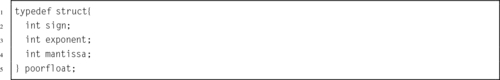
The structure shown in Listing 8.5 is a rather inefficient way to represent a fractional number, and may create different data structures on different machines. The sign only requires one bit, and the size of the exponent and mantissa are dependent upon the machine on which the code is compiled. The sign will use one bit, the exponent eight bits, and the mantissa 23 bits.
The C language includes the notion of bit fields. This allows the programmer to specify exactly how many bits are to be used for each field within a struct, Listing 8.6 shows a C data structure that consumes 32 bits on all machines and architectures. It provides the same fields as the structure in Listing 8.5, but specifies exactly how many bits each field consumes.
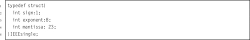
The compiler will compress this data structure into 32 bits, regardless of the natural word size of the machine.
The method of representing fractional numbers as a sign, exponent, and mantissa is very powerful, and IEEE has set standards for various floating point formats. These formats can be described using bit fields in C, as described above. Many processors have hardware that is specifically designed to perform arithmetic using the standard IEEE formatted data. The following sections highlight most of the IEEE defined numerical definitions.
The IEEE standard specifies the bitwise representation for numbers, and specifies parameters for how arithmetic is to be performed. The IEEE standard for numbers includes the possibility of having numbers that cannot be easily represented. For example, any quantity that is greater than the most positive representable value is positive infinity, and any quantity that is less than the most negative representable value is negative infinity. There are special bit patterns to encode these quantities. The programmer or hardware designer is responsible for ensuring that their implementation conforms to the IEEE standards. The following sections describe some of the IEEE standard data formats.
8.5.1 IEEE 754 Half-Precision
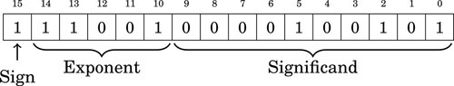
The half-precision format gives a 16-bit encoding for fractional numbers with a small range and low precision. There are situations where this format is adequate. If the computation is being performed on a very small machine, then using this format may result in significantly better performance than could be attained using one of the larger IEEE formats. However, in most situations, the programmer can achieve better performance and/or precision by using a fixed-point representation. The format is as follows:
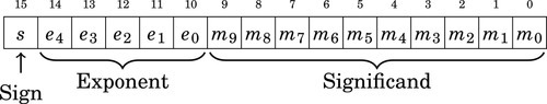
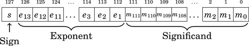
• The Significand (a.k.a. “Mantissa”) is stored using a sign-magnitude coding, with bit 15 being the sign bit.
• The exponent is an excess-15 number. That is, the number stored is 15 greater than the actual exponent.
• There are 10 bits of significand, but there are 11 bits of significand precision. There is a “hidden” bit, m10, between m9 and e0. When a number is stored in this format, it is shifted until its leftmost non-zero bit is in the hidden bit position, and the hidden bit is not actually stored. The exception to this rule is when the number is zero or very close to zero. The radix point is assumed to be between the hidden bit and the first bit stored. The radix point is then shifted by the exponent.
Table 8.1 shows how to interpret IEEE 754 Half-Precision numbers. The exponents 00000 and 11111 have special meaning. The value 00000 is used to represent zero and numbers very close to zero, and the exponent value 11111 is used to represent infinity and NaN. NaN, which is the abbreviation for not a number, is a value representing an undefined or unrepresentable value. One way to get NaN as a result is to divide infinity by infinity. Another is to divide zero by zero. The NaN value can indicate that there is a bug in the program, or that a calculation must be performed using a different method.
Table 8.1
Format for IEEE 754 half-precision
| Exponent | Significand = 0 | Significand≠0 | Equation |
| 00000 | ± 0 | subnormal | − 1sign × 2−14 × 0.significand |
| 00001 …11110 | normalized value | − 1sign × 2exp−15 × 1.significand | |
| 11111 |  | NaN | |
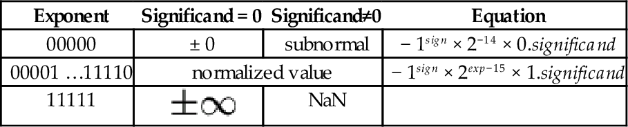
Subnormal means that the value is too close to zero to be completely normalized. The minimum strictly positive (subnormal) value is 2−24 ≈ 5.96 × 10⁻⁸. The minimum positive normal value is 2−14 ≈ 6.10 × 10⁻⁵. The maximum exactly representable value is (2 − 2−10) × 215 = 65504.
Examples

represents

represents

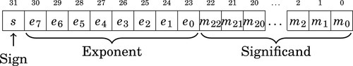
8.5.2 IEEE 754 Single-Precision
The single precision format provides a 23-bit mantissa and an 8-bit exponent, which is enough to represent a reasonably large range with reasonable precision. This type can be stored in 32 bits, so it is relatively compact. At the time that the IEEE standards were defined, most machines used a 32-bit word, and were optimized for moving and processing data in 32-bit quantities. For many applications this format represents a good trade-off between performance and precision.
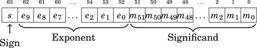
8.5.3 IEEE 754 Double-Precision
The double-precision format was designed to provide enough range and precision for most scientific computing requirements. It provides a 10-bit exponent and a 53-bit mantissa. When the IEEE 754 standard was introduced, this format was not supported by most hardware. That has changed. Most modern floating point hardware is optimized for the IEEE 754 double-precision standard, and most modern processors are designed to move 64-bit or larger quantities. On modern floating-point hardware, this is the most efficient representation.
However, processing large arrays of double-precision data requires twice as much memory, and twice as much memory bandwidth, as single-precision.
8.5.4 IEEE 754 Quad-Precision
The IEEE 754 Quad-Precision format was designed to provide enough range and precision for very demanding applications. It provides a 14-bit exponent and a 116-bit mantissa. This format is still not supported by most hardware. The first hardware floating point unit to support this format was the SPARC V8 architecture. As of this writing, the popular Intel x86 family, including the 64-bit versions of the processor, do not have hardware support for the IEEE 754 quad-precision format. On modern high-end processors such as the SPARC, this may be an efficient representation. However, for mid-range processors such as the Intel x86 family and the ARM, this format is definitely out of their league.
8.6 Floating Point Operations
Many processors do not have hardware support for floating point. On those processors, all floating point must be accomplished through software. Processors that do support floating point in hardware must have quite sophisticated circuitry to manage the basic operations on data in the IEEE 754 standard formats. Regardless of whether the operations are carried out in software or hardware, the basic arithmetic operations require multiple steps.
8.6.1 Floating Point Addition and Subtraction
The steps required for addition and subtraction of floating point numbers is the same, regardless of the specific format. The steps for adding or subtracting to floating point numbers a and b are as follows:
1. Extract the exponents Ea and Eb.
2. Extract the significands Ma and Mb. and convert them into 2’s complement numbers, using the signs Sa and Sb.
3. Shift the significand with the smaller exponent right by |Ea − Eb|.
4. Perform addition (or subtraction) on the significands to get the significand of the result, Mr. Remember that the result may require one more significant bit to avoid overflow.
5. If Mr is negative, then take the 2’s complement and set Sr to 1. Otherwise set Sr to 0.
6. Shift Mr until the leftmost 1 is in the “hidden” bit position, and add the shift amount to the smaller of the two exponents to form the new exponent Er.
7. Combine the sign Sr, the exponent Er, and significand Mr to form the result.
The complete algorithm must also provide for correct handling of infinity and NaN.
8.6.2 Floating Point Multiplication and Division
Multiplication and division of floating point numbers also requires several steps. The steps for multiplication and division of two floating point numbers a and b are as follows:
1. Calculate the sign of the result Sr.
2. Extract the exponents Ea and Eb.
3. Extract the significands Ma and Mb.
4. Multiply (or divide) the significands to form Mr.
5. Add (or subtract) the exponents (in excess-N) to get Er.
6. Shift Mr until the leftmost 1 is in the “hidden” bit position, and add the shift amount to Er.
7. Combine the sign S, the exponent Er, and significand Mr to form the result.
The complete algorithm must also provide for correct handling of infinity and NaN.
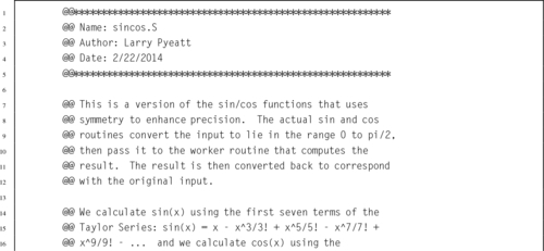
8.7 Computing Sine and Cosine
It has been said, and is commonly accepted, that “you can’t beat the compiler.” The meaning of this statement is that using hand-coded assembly language is futile and/or worthless because the compiler is “smarter” than a human. This statement is a myth, as will now be demonstrated.
There are many mathematical functions that are useful in programming. Two of the most useful functions are  and
and  . However, these functions are not always implemented in hardware, particularly for fixed-point representations. If these functions are required for fixed-point computation, then they must be written in software. These two functions have some nice properties that can be exploited. In particular:
• If we have the function, then we can calculate using the relationship

Therefore, we only need to get the sine function working, and then we can implement cosine with only a little extra effort.
• is cyclical, so  . This means that we can limit the domain of our function to the range [−π,π].
• is symmetric, so that  . This means that we can further restrict the domain to [0,π].
• After we restrict the domain to [0,π], we notice another symmetry,  and we can further restrict the domain to
  .
.
• The range of both functions, and , is in the range [−1,1].
If we exploit all of these properties, then we can write a single shared function to be used by both sine and cosine. We will name this function sinq, and choose the following fixed-point formats:
• sinq will accept x as an S(1,30), and
• sinq will return an S(1,30)
These formats were chosen because S(1,30) is a good format for storing a signed number between zero and  , and also the optimal format for storing a signed number between one and negative one.
The sine function will map x into the domain accepted by sinq and then call sinq to do the actual work. If the result should be negative, then the sine function will negate it before returning. The cosine function will use the relationship previously mentioned, and call the sine function.
We have now reduced the problem to one of approximating within the range . An approximation to the function can be calculated using the Taylor Series:
The first few terms of the series should be sufficient to achieve a good approximation. The maximum value possible for the seventh term is  , which indicates that our function should be accurate to at least 25 bits using seven terms. If more accuracy is desired, then additional terms can be added.
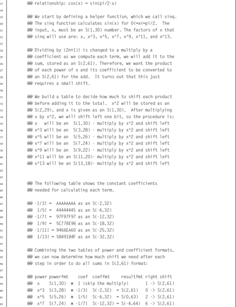
8.7.1 Formats for the Powers of x
The numerators in the first nine terms of the Taylor series approximation are: x, x3, x5, x7, x9, x11, x13, x15, and x17. Given an S(1,30) format for x, we can predict the format for the numerator of each successive term in the Taylor series. If we simply perform successive multiplies, then we would get the following formats for the powers of x:
| Term | Format | 32-bit |
| x | S(1,30) | S(1,30) |
| x3 | S(3,90) | S(3,28) |
| x5 | S(5,150) | S(5,26) |
| x7 | S(7,210) | S(7,24) |
| x9 | S(9,270) | S(9,22) |
| x11 | S(11,330) | S(11,20) |
| x13 | S(13,390) | S(13,18) |
The middle column in the table shows that the format for x17 would require 528 bits if all of the fractional bits are retained. Dealing with a number at that level of precision would be slow and impractical. We will, of necessity, need to limit the number of bits used. Since the ARM processor provides a multiply instruction involving two 32-bit numbers, we choose to truncate the numerators to 32 bits. The third column in the table indicates the resulting format for each term if precision is limited to 32 bits.
On further consideration of the Taylor series, we notice that each of the above terms will be divided by a constant. Instead of dividing, we can multiply by the reciprocal of the constant. We will create a similar table holding the formats and constants for the factorial terms. With a bit of luck, the division (implemented as multiplication) in each term will result in a reasonable format for each resulting term.
8.7.2 Formats and Constants for the Factorial Terms
The first term of the Taylor series is  , so we can simply skip the division. The second term is
  and the third term is
  We can convert
  to binary as follows:


Since the pattern repeats, we can conclude that  . Since we need a negative number, we take the two’s complement, resulting in
  . Represented as an S(1,30), this would be
Since the first four bits are one, we can remove three bits and store it as:
In hexadecimal, this is AAAAAAAA16.
Performing the same operations, we find that  can be converted to binary as follows:


Since the fraction in the seventh row is the same as the fraction in the third row, we know that the table will repeat forever. Therefore,  . Since the first six bits to the right of the radix are all zero, we can remove the first five bits. Also adding one to the least significant bit to account for rounding error yields the following S(−6,32):
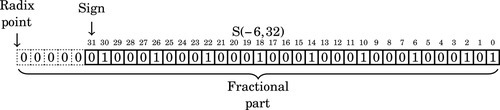
In hexadecimal, the number to be multiplied is 4444444516. Note that since is a positive number, the reciprocal was incremented by one to avoid round-off errors. We can apply the same procedure to the remaining terms, resulting in the following table:
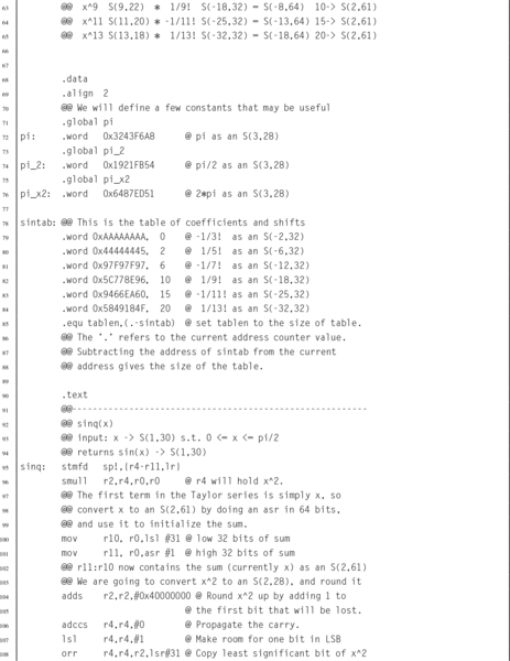
8.7.3 Putting it All Together
We want to keep as much precision as is reasonably possible for our intermediate calculations. Using 64 bits of precision for all intermediate calculations will give a good trade-off between performance and precision. The integer portion should never require more than two bits, so we choose an S(2,61) as our intermediate representation. If we combine the previous two tables, we can determine what the format of each complete term will be. This is shown in Table 8.2.
Table 8.2
Result formats for each term
| Numerator | Reciprocal | Result | ||||
| Term | Value | Format | Value | Format | Hex | Format |
| 1 | x | S(1,30) | Extend to 64 bits and shift right | S(2,61) | ||
| 2 | x3 | S(3,28) | | S(−2,32) | AAAAAAAA | S(2, 61) |
| 3 | x5 | S(5,26) | | S(−6,32) | 44444444 | S(0, 63) |
| 4 | x7 | S(7,24) |  | S(−12,32) | 97F97F97 | S(−4, 64) |
| 5 | x9 | S(9,22) |  | S(−18,32) | 5C778E96 | S(−8, 64) |
| 6 | x11 | S(11,20) |  | S(−25,32) | 9466EA60 | S(−13, 64) |
| 7 | x13 | S(13,18) |  | S(−32,32) | 5849184F | S(−18, 64) |
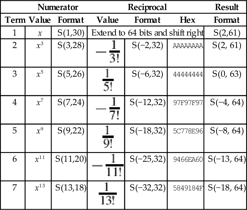
Note that the formats were truncated to fit in a 64-bit result. We can now see that the formats for the first nine terms of the Taylor series are reasonably similar. They all require exactly 64 bits, and the radix points can be shifted so that they are aligned for addition. In order to make the shifting and adding process easier, we will pre-compute the shift amounts and store them in a look-up table.
Table 8.3 shows the shifts that are necessary to convert each term to an S(2,61) so that it can be added to the running total.
Table 8.3
Shifts required for each term
| Term Number | Original Format | Shift Amount | Resulting Format |
| 1 | S(1,30) | 1 | S(2,61) |
| 2 | S(2,61) | 0 | S(2,61) |
| 3 | S(0,63) | 2 | S(2,61) |
| 4 | S(−4,64) | 6 | S(2,61) |
| 5 | S(−8,64) | 10 | S(2,61) |
| 6 | S(−13,64) | 15 | S(2,61) |
| 7 | S(−18,64) | 20 | S(2,61) |
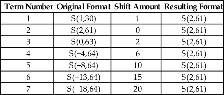
Note that the seventh term contributes very little to the final 32-bit sum which is stored in the upper 32 bits of the running total. We now have all of the information that we need in order to implement the function. Listing 8.7 shows how the sine and cosine function can be implemented in ARM assembly using fixed point computation, and Listing 8.8 shows a main program which prints a table of values and their sine and cosines.
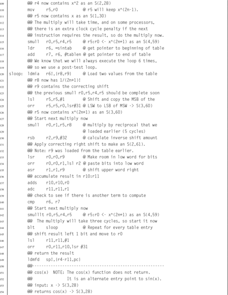
 and using fixed-point calculations.
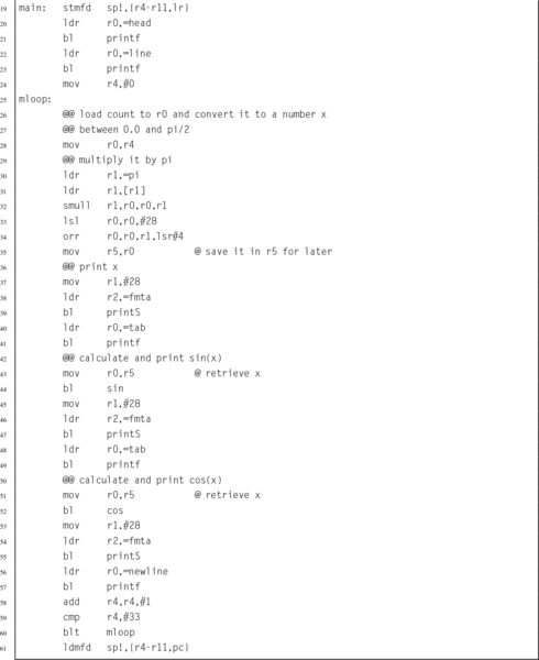 and functions can be used to print a table.
8.7.4 Performance Comparison
In some situations it can be very advantageous to use fixed-point math. For example, when using an ARMv6 or older processor, there may not be a hardware floating point unit available. Table 8.4 shows the CPU time required for running a program to compute the sine function on 10,000,000 random values, using various implementations of the sine function. In each case, the program main() function was written in C. The only difference in the six implementations was the data type (which could be fixed-point, IEEE single precision, or IEEE double precision), and the sine function that was used. The times shown in the table include only the amount of CPU time actually used in the sine function, and do not include the time required for program startup, storage allocation, random number generation, printing results, or program exit. The six implementations are as follows:
Table 8.4
Performance of sine function with various implementations
| Optimization | Implementation | CPU seconds |
| None | 32-bit Fixed Point Assembly | 3.85 |
| 32-bit Fixed Point C | 18.99 | |
| Single Precision Software Float C | 56.69 | |
| Double Precision Software Float C | 55.95 | |
| Single Precision VFP C | 11.60 | |
| Double Precision VFP C | 11.48 | |
| Full | 32-bit Fixed Point Assembly | 3.22 |
| 32-bit Fixed Point C | 5.02 | |
| Single Precision Software Float C | 20.53 | |
| Double Precision Software Float C | 54.51 | |
| Single Precision VFP C | 3.70 | |
| Double Precision VFP C | 11.08 |
32-bit Fixed Point Assembly The sine function is computed using the code shown in Listing 8.7.
32-bit Fixed Point C The sine function is computed using exactly the same algorithm as in Listing 8.7, but it is implemented in C rather than Assembly.
Single Precision Software Float C Sine is computed using the floating point sine function which is provided by the GCC C compiler. The code is compiled for an ARMv6 or earlier processor without hardware floating point support. The C code is written to use IEEE single precision floating point numbers.
Double Precision Software Float C Exactly the same as the previous method, but using IEEE double precision instead of single precision.
Single Precision VFP C Sine is computed using the floating point sine function which is provided by the GCC C compiler. The code is compiled for the ARMv6 or later processor using hardware floating point support. The C code is written to use IEEE single precision floating point numbers.
Double Precision VFP C Same as the previous method, but using IEEE double precision instead of single precision.
Each of the six implementations was compiled both with and without compiler optimizations, resulting in a total of 12 test cases. All cases were run on a standard Raspberry Pi model B with the default CPU clock rate.
From Table 8.4, it is clear that the fixed-point implementation written in assembly beats the code generated by the compiler in every case. The closest that the compiler can get is when it can use the VFP hardware floating point unit and the compiler is run with full optimization. Even in that case the fixed-point assembly implementation is almost 15% faster than the single precision floating point implementation, and has 33% more precision (32 bits versus 24 bits). In the worst case, when a VFP hardware unit is not available, the assembly code beats the compiler by a whopping 638% in speed and 33% in precision for single precision floats, and is 1692% faster than double precision floating point at a cost of 41% in precision. Note that even with floating point hardware support, fixed point in assembly is still 3.44 times as fast as the C compiler code.
Similar results could be obtained on any processor architecture, and any reasonably complex mathematical problem. When developing software for small systems, the developer must weigh the costs and benefits of alternative implementations. For battery powered systems, it is important to realize that choices of hardware and software can affect power consumption even more strongly than computing performance. First, the power used by a system which includes a hardware floating point processor will be consistently higher than that of a system without one. Second, the reduction in processing time required for the job is closely related to the reduction in power required. Therefore, for battery operated systems, A fixed-point implementation could greatly extend battery life. The following statements summarize the results from the experiment in this section:
1. A competent assembly programmer can beat the assembler, in some cases by a very large margin.
2. If computational performance is critical, then a well-designed fixed-point implementation will usually outperform even a hardware-accelerated floating point implementation.
3. If there is no hardware support for floating point, then floating point performance is extremely poor, and fixed point will always provide the best performance.
4. If battery life is a consideration, then a fixed-point implementation can have an enormous advantage.
Note also from the table that the assembly language version of the fixed-point sine function beats the identical C version by a wide margin. Section 9.8.2 will demonstrate that a good assembly language programmer who is familiar with the floating point hardware can beat the compiler by an even wider performance margin.
8.8 Ethics Case Study: Patriot Missile Failure
Fixed-point arithmetic is very efficient on modern computers. However it is incumbent upon the programmer to track the radix point at all stages of the computation, and to ensure that a sufficient number of bits are provided on both sides of the radix point. The programmer must ensure that all computations are carried out with the desired level of precision, resolution, accuracy, range, and dynamic range. Failure to do so can have serious consequences.
On February 25, 1991, during the Gulf War, an American Patriot Missile battery in Dharan, Saudi Arabia, failed to intercept an incoming Iraqi SCUD missile. The SCUD struck an American army barracks, killing 28 soldiers and injuring around 98 other people. The cause was an inaccurate calculation of the time elapsed since the system was last booted.
The hardware clock on the system counted the time in tenths of a second since the last reboot. Current time, in seconds, was calculated by multiplying that number by . For this calculation, was represented as a U(1,23) fixed-point number. Since cannot be represented precisely in a fixed number of bits, there was round-off error in the calculations. The small imprecision, when multiplied by a large number, resulted in significant error. The longer the system ran after boot, the larger the error became.
The system determined whether or not it should fire by predicting where the incoming missile would be at a specific time in the future. The time and predicted location were then fed to a second system which was responsible for locking onto the target and firing the Patriot missile. The system would only fire when the missile was at the proper location at the specified time. If the radar did not detect the incoming missile at the correct time and location, then the system would not fire.
At the time of the failure, the Patriot battery had been up for around 100 h. We can estimate the error in the timing calculations by considering how the binary number was stored. The binary representation of is  . Note that it is a non-terminating, repeating binimal. The 24-bit register in the Patriot could only hold the following set of bits:
This resulted in an error of  . The error can be computed in base 10 as:


To find out how much error was in the total time calculation, we multiply e by the number of tenths of a second in 100 h. This gives 9.5 × 10−8 × 100 × 60 × 60 × 10 = 0.34 s. A SCUD missile travels at about 1,676 m/s. Therefore it travels about 570 m in 0.34 s. Because of this, the targeting and firing system was expecting to find the SCUD at a location that was over half a kilometer from where it really was. This was far enough that the incoming SCUD was outside the “range gate” that the Patriot tracked. It did not detect the SCUD at its predicted location, so it could not lock on and fire the Patriot.
This is an example of how a seemingly insignificant error can lead to a major failure. In this case, it led to loss of life and serious injury. Ironically, one factor that contributed to the problem was that part of the code had been modified to provide more accurate timing calculations, while another part had not. This meant that the inaccuracies did not cancel each other. Had both sections of code been re-written, or neither section changed, then the issue probably would not have surfaced.
The Patriot system was originally designed in 1974 to be mobile and to defend against aircraft that move much more slowly than ballistic missiles. It was expected that the system would be moved often, and therefore the computer would be rebooted frequently. Also, the slow-moving aircraft would be much easier to track, and the error in predicting where it is expected to be would not be significant. The system was modified in 1986 to be capable of shooting down Soviet ballistic missiles. A SCUD missile travels at about twice the speed of the Soviet missiles that the system was re-designed for.
The system was deployed to Iraq in 1990, and successfully shot down a SCUD missile in January of 1991. In mid-February of 1991, Israeli troops discovered that the system became inaccurate if it was allowed to run for long periods of time. They claimed that the system would become unreliable after 20 hours of operation. U.S. military did not think the discovery was significant, but on February 16th, a software update was released. Unfortunately, the update could not immediately reach all units because of wartime difficulties in transportation. The Army released a memo on February 21st, stating that the system was not to be run for “very long times,” but did not specify how long a “very long time” would be. The software update reached Dhahran one day after the Patriot Missile system failed to intercept a SCUD missile, resulting in the death of 28 Americans and many more injuries.
Part of the reason this error was not found sooner was that the program was written in assembly language, and had been patched several times in its 15-year life. The code was difficult to understand and maintain, and did not conform to good programming practices. The people who worked to modify the code to handle the SCUD missiles were not as familiar with the code as they would have been if it were written more recently, and time was a critical factor. Prolonged testing could have caused a disaster by keeping the system out of the hands of soldiers in a time of war. The people at Raytheon Labs had some tough decisions to make. It cannot be said that Raytheon was guilty of negligence or malpractice. The problem with the system was not necessarily the developers, but that the system was modified often and in inconsistent ways, without complete understanding.
8.9 Chapter Summary
Sometimes it is desirable to perform calculations involving non-integral numbers. The two common ways to represent non-integral numbers in a computer are fixed point and floating point. A fixed point representation allows the programmer to perform calculations with non-integral numbers using only integer operations. With fixed point, the programmer must track the radix point throughout the computation. Floating point representations allow the radix point to be tracked automatically, but require much more complex software and/or hardware. Fixed point will usually provide better performance than floating point, but requires more programming skill.
Fractional numbers in radix notation may not terminate in all bases. Numbers which terminate in base two will also terminate in base ten, but the converse is not true. Programmers should avoid counting using fractions which do not terminate in base two, because it leads to the accumulation of round-off errors.
Exercises
8.1 Perform the following base conversions:
(a) Convert 10110.0012 to base ten.
(b) Convert 11000.01012 to base ten.
(c) Convert 10.12510 to binary.
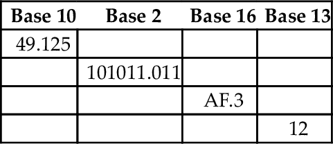
8.2 Complete the following table (assume all values represent positive fixed-point numbers):
8.3 You are working on a problem involving real numbers between −2 and 2 on a computer that has 16-bit integer registers and no hardware floating point support. You decide to use 16-bit fixed-point arithmetic.
(a) What fixed-point format should you use?
(b) Draw a diagram showing the sign, if any, radix point, integer part, and fractional part.
(c) What is the precision, resolution, accuracy, and range of your format?
8.4 What is the resulting type of each of the following fixed-point operations?
(b) S(3,4)÷U(4,20)
8.5 Convert 26.64062510 to a binary U(18,14) representation. Show the ARM assembly code necessary to load that value into register r4.
8.6 For each of the following fractions, indicate whether or not it will terminate in bases 2, 5, 7, and 10.

(b) 
(c) 
(d) 
(e) 
8.7 What is the exact value of the binary number 0011011100011010 when interpreted as an IEEE half-precision number? Give your answer in base ten.
8.8 The “Software Engineering Code of Ethics And Professional Practice” states that a responsible software engineer should “Approve software only if they have well-founded belief that it is safe, meets specifications, passes appropriate tests…” (sub-principle 1.03) and “Ensure adequate testing, debugging, and review of software…on which they work” (sub-principle 3.10).
The software engineering code of ethics also states that a responsible software engineer should “Treat all forms of software maintenance with the same professionalism as new development.”
(a) Explain how the Software Engineering Code of Ethics And Professional Practice were violated by the Patriot Missile system developers.
(b) How should the engineers and managers at Raytheon have responded when they were asked to modify the Patriot Missile System to work outside of its original design parameters?
(c) What other ethical and non-ethical considerations may have contributed to the disaster?