Table of Contents for
Modern Assembly Language Programming with the ARM Processor
 Modern Assembly Language Programming with the ARM Processor
Published by
Newnes, 2016
Modern Assembly Language Programming with the ARM Processor
Published by
Newnes, 2016
- Modern Assembly Language Programming with the ARM Processor
- Cover image
- Title page
- Table of Contents
- Copyright
- List of Tables
- List of Figures
- List of Listings
- Preface
- Companion Website
- Acknowledgments
- Part I: Assembly as a Language
- Chapter 1: Introduction
- Chapter 2: GNU Assembly Syntax
- Chapter 3: Load/Store and Branch Instructions
- Chapter 4: Data Processing and Other Instructions
- Chapter 5: Structured Programming
- Chapter 6: Abstract Data Types
- Part II: Performance Mathematics
- Chapter 7: Integer Mathematics
- Chapter 8: Non-Integral Mathematics
- Chapter 9: The ARM Vector Floating Point Coprocessor
- Chapter 10: The ARM NEON Extensions
- 10.10 Multiplication and Division
- Part III: Accessing Devices
- Chapter 11: Devices
- Chapter 12: Pulse Modulation
- Chapter 13: Common System Devices
- Chapter 14: Running Without an Operating System
- Index
The ARM NEON Extensions
Abstract
This chapter begins with an overview of the NEON extensions and explains the relationship between VFP and NEON. The NEON registers are explained, and the syntax for NEON instructions is explained. Next, each of the NEON instructions are explained, with short examples. In some cases, extended examples and figures are provided to help explain the operation of complex instructions. After all of the instructions are explained, another implementation of sine is presented and compared to previous implementations and with the GCC sine function. It is shown that NEON gives a significant performance advantage over VFP and hand coded assembly is much faster than the sin function provided by the compiler.
Keywords
Single instruction multiple data (SIMD); Vector; Vector element; Instruction level parallelism; Lane
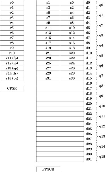
The ARM VFP coprocessor has been replaced or augmented by the NEON architecture on ARMv7 and higher systems. NEON extends the VFP instruction set with about 125 instructions and pseudo-instructions to support not only floating point, but also integer and fixed point. NEON also supports Single Instruction, Multiple Data (SIMD) operations. All NEON processors have the full set of 32 double precision VFP registers, but NEON adds the ability to view the register set as 16 128-bit (quadruple-word) registers, named q0 through q15.
A single NEON instruction can operate on up to 128 bits, which may represent multiple integer, fixed point, or floating point numbers. For example, if two of the 128-bit registers each contain eight 16-bit integers, then a single NEON instruction can add all eight integers from one register to the corresponding integers in the other register, resulting in eight simultaneous additions. For certain applications, this SIMD architecture can result in extremely fast and efficient implementations. NEON is particularly useful at handling streaming video and audio, but also can give very good performance on floating point intensive tasks. NEON instructions perform parallel operations on vectors. NEON deprecates the use of VFP vector mode covered in Section 9.2.2. On most NEON systems, using the VFP vector mode will result in an exception, which transfers control to the support code which emulates vector mode in software. This causes a severe performance penalty, so VFP vector mode should not be used on NEON systems.
Fig. 10.1 shows the ARM integer, VFP, and NEON register set. NEON views each register as containing a vector of 1, 2, 4, 8, or 16 elements, all of the same size and type. Individual elements of each vector can also be accessed as scalars. A scalar can be 8 bits, 16 bits, 32 bits, or 64 bits. The instruction syntax is extended to refer to scalars using an index, x, in a doubleword register. Dm[x] is element x in register Dm. The size of the elements is given as part of the instruction. Instructions that access scalars can access any element in the register bank.
10.1 NEON Intrinsics
The GCC compiler gives C (and C++) programs direct access to the NEON instructions through the NEON intrinsics. The intrinsics are a large set of functions that are built into the compiler. Most of the intrinsics functions map to one NEON instruction. There are additional functions provided for typecasting (reinterpreting) NEON vectors, so that the C compiler does not complain about mismatched types. It is usually shorter and more efficient to write the NEON code directly as assembly language functions and link them to the C code. However only those who know assembly language are capable of doing that.
10.2 Instruction Syntax
Some instructions require specific register types. Other instructions allow the programmer to choose single word, double word, or quad word registers. If the instruction requires single precision registers, then the registers are specified as Sd for the destination register, Sn for the first operand register, and Sm for the second operand register. If the instruction requires only two registers, then Sn is not used. The lower-case letter is replaced with a valid register number. The register name is not case sensitive, so S10 and s10 are both valid names for single precision register 10.
The syntax of the NEON instructions can be described using a relatively simple notation. The notation consists of the following elements:
{item} Braces around an item indicate that the item is optional. For example, many operations have an optional condition, which is written as {<cond>}.
Ry An ARM integer register. y can be any number in the range 0{15.
Sy A 32-bit or single precision register. y can be any number in the range 0{31.
Dy A 64-bit or double precision register. y can be any number in the range 0{31.
Qy A quad word register. y can be any number in the range 0{15.
Fy A VFP register. F must be either s for a single word register, or d for a double word register. y can be any valid register number.
Ny A NEON or VFP register. N must be either s for a single word register, d for a double word register, or q for a quad word register. y can be any valid register number.
Vy A NEON vector register. V must be replaced with d for a double word register, or q for a quad word register. y can be any valid register number.
Vy[x] A NEON scalar (vector element). The size of the scalar is defined as part of the instruction. V must be replaced with d for a double word register, or q for a quad word register. y can be any valid register number. x specifies which scalar element of Vy is to be used. Valid values for x can be deduced by the size of Vy and the size of the scalars that the instruction uses.
<op> Operation specific part of a general instruction format
<n> An integer usually indicating a specific instruction version
<size> An integer indicating the number of bits used
<cond> ARM condition code from Table 3.2
<type> Many instructions operate on one or more of the following specific data types:
i16 Untyped 16 bits
i32 Untyped 32 bits
i64 Untyped 64 bits
s8 Signed 8-bit integer
s16 Signed 16-bit integer
s32 Signed 32-bit integer
s64 Signed 64-bit integer
u8 Unsigned 8-bit integer
u16 Unsigned 16-bit integer
u32 Unsigned 32-bit integer
u64 Unsigned 64-bit integer
f16 IEEE 754 half precision floating point
f32 IEEE 754 single precision floating point
f64 IEEE 754 double precision floating point
<list> A brace-delimited list of up to four NEON registers, vectors, or scalars. The general form is {Dn,D(n+a),D(n+2a),D(n+3a)} where a is either 1 or 2.
<align> Specifies the memory alignment of structured data for certain load and store operations.
<imm> An immediate value. The required format for immediate values depends on the instruction.
<fbits> Specifies the number of fraction bits in fixed point numbers.
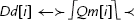
The following function definitions are used in describing the effects of many of the instructions:
 The floor function maps a real number, x, to the next smallest integer.
 The saturate function limits the value of x to the highest or lowest value that can be stored in the destination register.
 The round function maps a real number, x, to the nearest integer.
 The narrow function reduces a 2n bit number to an n bit number, by taking the n least significant bits.
 The extend function converts an n bit number to a 2n bit number, performing zero extension if the number is unsigned, or sign extension if the number is signed.
10.3 Load and Store Instructions
These instructions can be used to perform interleaving of data when structured data is loaded or stored. The data should be properly aligned for best performance. These instructions are very useful for common multimedia data types.
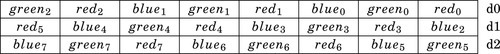
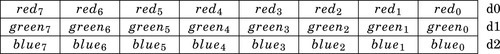
For example, image data is typically stored in arrays of pixels, where each pixel is a small data structure such as the pixel struct shown in Listing 5.37. Since each pixel is three bytes, and a d register is 8 bytes, loading a single pixel into one register would be inefficient. It would be much better to load multiple pixels at once, but an even number of pixels will not fit in a register. It will take three doubleword or quadword registers to hold an even number of pixels without wasting space, as shown in Fig. 10.2. This is the way data would be loaded using a VFP vldr or vldm instruction. Many image processing operations work best if each color “channel” is processed separately. The NEON load and store vector instructions can be used to split the image data into color channels, where each channel is stored in a different register, as shown in Fig. 10.3.
Other examples of interleaved data include stereo audio, which is two interleaved channels, and surround sound, which may have up to nine interleaved channels. In all of these cases, most processing operations are simplified when the data is separated into non-interleaved channels.
10.3.1 Load or Store Single Structure Using One Lane
These instructions are used to load and store structured data across multiple registers:
vld<n> Load Structured Data, and
vst<n> Store Structured Data.
They can be used for interleaving or deinterleaving the data as it is loaded or stored, as shown in Fig. 10.3.
Syntax
• <op> must be either ld or st.
• <n> must be one of 1, 2, 3, or 4.
• <size> must be one of 8, 16, or 32.
• <list> specifies the list of registers. There are four list formats:
2. {Dd[x], D(d+a)[x]}
3. {Dd[x], D(d+a)[x], D(d+2a)[x]}
4. {Dd[x], D(d+a)[x], D(d+2a)[x], D(d+3a)[x]}
where a can be either 1 or 2. Every register in the list must be in the range d0-d31.
• Rn is the ARM register containing the base address. Rn cannot be pc.
• <align> specifies an optional alignment. If <align> is not specified, then standard alignment rules apply.
• The optional ! indicates that Rn is updated after the data is transferred. This is similar to the ldm and stm instructions.
• Rm is an ARM register containing an offset from the base address. If Rm is present, Rn is updated to Rn + Rm after the address is used to access memory. Rm cannot be sp or pc.
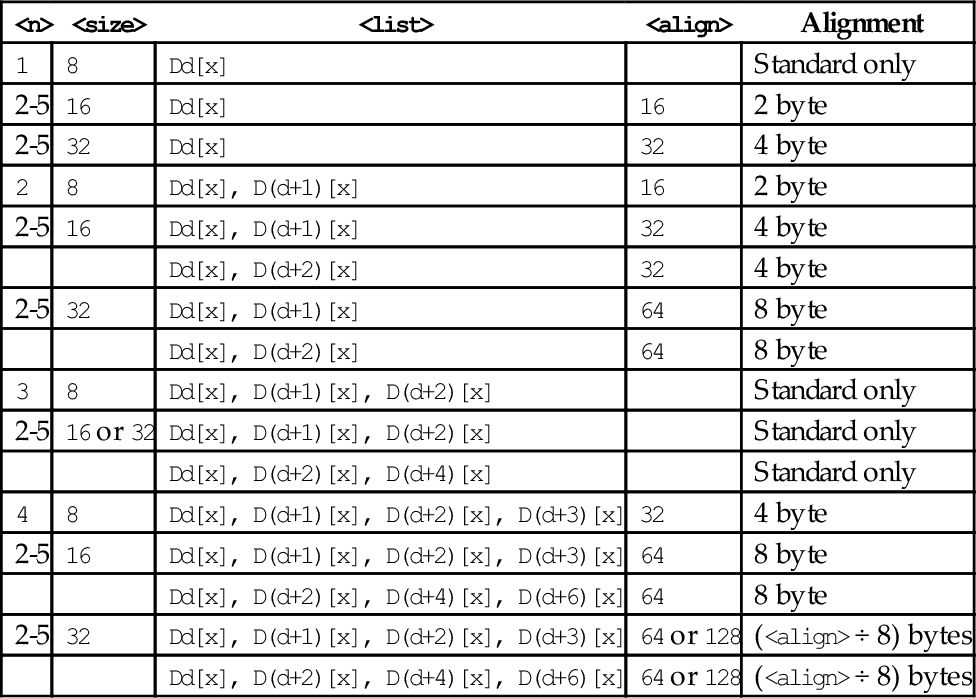
Table 10.1 shows all valid combinations of parameters for these instructions. Note that the same vector element (scalar) x must be used in each register. Up to four registers can be specified. If the structure has more than four fields, then these instructions can be used repeatedly to load or store all of the fields.
Table 10.1
Parameter combinations for loading and storing a single structure
| <n> | <size> | <list> | <align> | Alignment |
| 1 | 8 | Dd[x] | Standard only | |
| 2-5 | 16 | Dd[x] | 16 | 2 byte |
| 2-5 | 32 | Dd[x] | 32 | 4 byte |
| 2 | 8 | Dd[x], D(d+1)[x] | 16 | 2 byte |
| 2-5 | 16 | Dd[x], D(d+1)[x] | 32 | 4 byte |
| Dd[x], D(d+2)[x] | 32 | 4 byte | ||
| 2-5 | 32 | Dd[x], D(d+1)[x] | 64 | 8 byte |
| Dd[x], D(d+2)[x] | 64 | 8 byte | ||
| 3 | 8 | Dd[x], D(d+1)[x], D(d+2)[x] | Standard only | |
| 2-5 | 16 or 32 | Dd[x], D(d+1)[x], D(d+2)[x] | Standard only | |
| Dd[x], D(d+2)[x], D(d+4)[x] | Standard only | |||
| 4 | 8 | Dd[x], D(d+1)[x], D(d+2)[x], D(d+3)[x] | 32 | 4 byte |
| 2-5 | 16 | Dd[x], D(d+1)[x], D(d+2)[x], D(d+3)[x] | 64 | 8 byte |
| Dd[x], D(d+2)[x], D(d+4)[x], D(d+6)[x] | 64 | 8 byte | ||
| 2-5 | 32 | Dd[x], D(d+1)[x], D(d+2)[x], D(d+3)[x] | 64 or 128 | (<align> ÷ 8) bytes |
| Dd[x], D(d+2)[x], D(d+4)[x], D(d+6)[x] | 64 or 128 | (<align> ÷ 8) bytes |
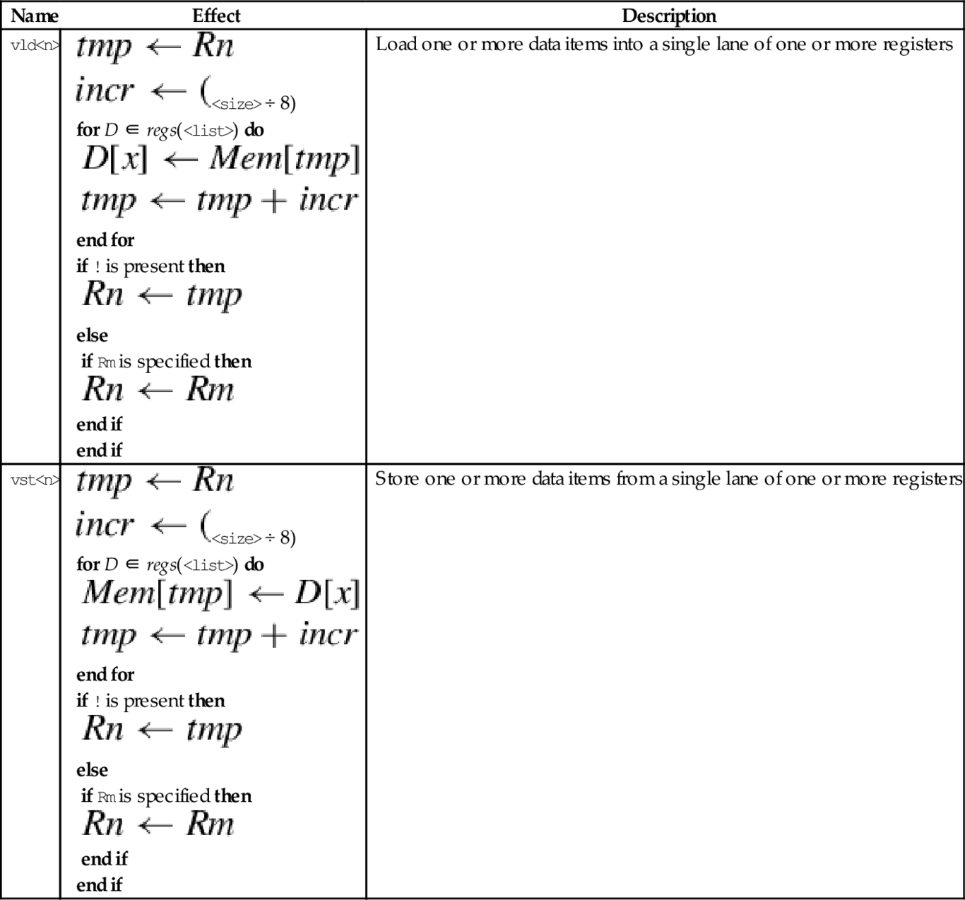
Operations
| Name | Effect | Description |
| vld<n> |
for D ∈ regs(<list>) do end for if ! is present then else if Rm is specified then end if end if | Load one or more data items into a single lane of one or more registers |
| vst<n> |
for D ∈ regs(<list>) do end for if ! is present then else if Rm is specified then end if end if | Store one or more data items from a single lane of one or more registers |


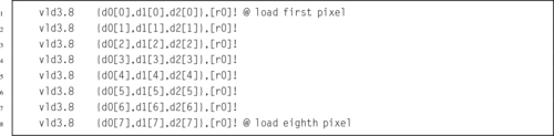
Examples
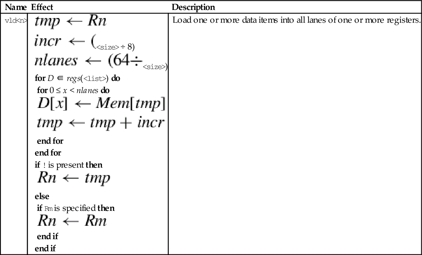
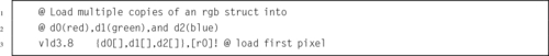
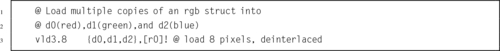
10.3.2 Load Copies of a Structure to All Lanes
This instruction is used to load multiple copies of structured data across multiple registers:
vld<n> Load Copies of Structured Data.
The data is copied to all lanes. This instruction is useful for initializing vectors for use in later instructions.
Syntax
• <n> must be one of 1, 2, 3, or 4.
• <size> must be one of 8, 16, or 32.
• <list> specifies the list of registers. There are four list formats:
2. {Dd[], D(d+a)[]}
3. {Dd[], D(d+a)[], D(d+2a)[]}
4. {Dd[], D(d+a)[], D(d+2a)[], D(d+3a)[]}
where a can be either 1 or 2. Every register in the list must be in the range d0-d31.
• Rn is the ARM register containing the base address. Rn cannot be pc.
• <align> specifies an optional alignment. If <align> is not specified, then standard alignment rules apply.
• The optional ! indicates that Rn is updated after the data is transferred. This is similar to the ldm and stm instructions.
• Rm is an ARM register containing an offset from the base address. If Rm is present, Rn is updated to Rn + Rm after the address is used to access memory. Rm cannot be sp or pc.
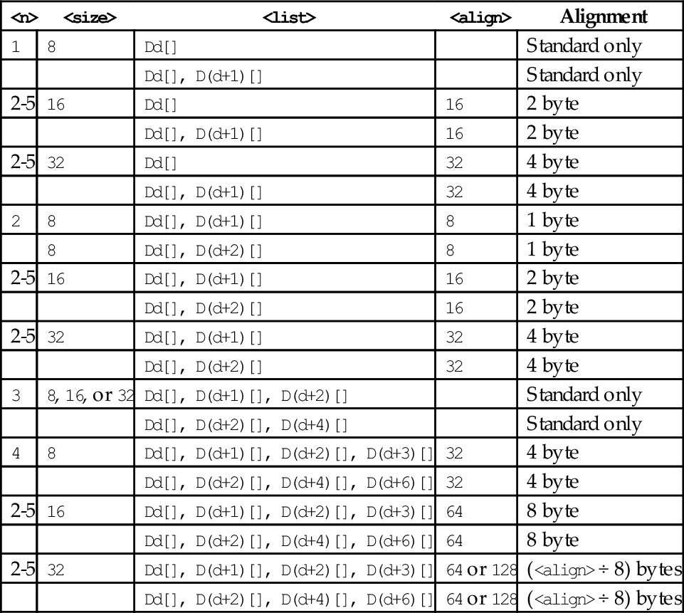
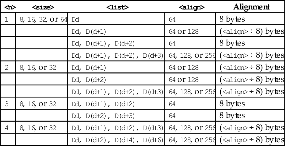
Table 10.2 shows all valid combinations of parameters for this instruction. Note that the vector element number is not specified, but the brackets [] must be present. Up to four registers can be specified. If the structure has more than four fields, then this instruction can be repeated to load or store all of the fields.
Table 10.2
Parameter combinations for loading multiple structures
| <n> | <size> | <list> | <align> | Alignment |
| 1 | 8 | Dd[] | Standard only | |
| Dd[], D(d+1)[] | Standard only | |||
| 2-5 | 16 | Dd[] | 16 | 2 byte |
| Dd[], D(d+1)[] | 16 | 2 byte | ||
| 2-5 | 32 | Dd[] | 32 | 4 byte |
| Dd[], D(d+1)[] | 32 | 4 byte | ||
| 2 | 8 | Dd[], D(d+1)[] | 8 | 1 byte |
| 8 | Dd[], D(d+2)[] | 8 | 1 byte | |
| 2-5 | 16 | Dd[], D(d+1)[] | 16 | 2 byte |
| Dd[], D(d+2)[] | 16 | 2 byte | ||
| 2-5 | 32 | Dd[], D(d+1)[] | 32 | 4 byte |
| Dd[], D(d+2)[] | 32 | 4 byte | ||
| 3 | 8, 16, or 32 | Dd[], D(d+1)[], D(d+2)[] | Standard only | |
| Dd[], D(d+2)[], D(d+4)[] | Standard only | |||
| 4 | 8 | Dd[], D(d+1)[], D(d+2)[], D(d+3)[] | 32 | 4 byte |
| Dd[], D(d+2)[], D(d+4)[], D(d+6)[] | 32 | 4 byte | ||
| 2-5 | 16 | Dd[], D(d+1)[], D(d+2)[], D(d+3)[] | 64 | 8 byte |
| Dd[], D(d+2)[], D(d+4)[], D(d+6)[] | 64 | 8 byte | ||
| 2-5 | 32 | Dd[], D(d+1)[], D(d+2)[], D(d+3)[] | 64 or 128 | (<align> ÷ 8) bytes |
| Dd[], D(d+2)[], D(d+4)[], D(d+6)[] | 64 or 128 | (<align> ÷ 8) bytes |
Operations

Examples
10.3.3 Load or Store Multiple Structures
These instructions are used to load and store multiple data structures across multiple registers with interleaving or deinterleaving:
vld<n> Load Multiple Structured Data, and
vst<n> Store Multiple Structured Data.
Syntax
• <op> must be either ld or st.
• <n> must be one of 1, 2, 3, or 4.
• <size> must be one of 8, 16, or 32.
• <list> specifies the list of registers. There are four list formats:
2. {Dd, D(d+a)}
3. {Dd, D(d+a), D(d+2a)}
4. {Dd, D(d+a), D(d+2a), D(d+3a)}
where a can be either 1 or 2. Every register in the list must be in the range d0-d31.
• Rn is the ARM register containing the base address. Rn cannot be pc.
• <align> specifies an optional alignment. If <align> is not specified, then standard alignment rules apply.
• The options ! indicates that Rn is updated after the data is transferred, similar to the ldm and stm instructions.
• Rm is an ARM register containing an offset from the base address. If Rm is present, Rn is updated to Rn + Rm after the address is used to access memory. Rm cannot be sp or pc.
Table 10.3 shows all valid combinations of parameters for this instruction. Note that the scalar is not specified and the instructions work on all multiple vector elements. Up to four registers can be specified. If the structure has more than four fields, then this instruction can be repeated to load or store all of the fields.
Table 10.3
Parameter combinations for loading copies of a structure
| <n> | <size> | <list> | <align> | Alignment |
| 1 | 8, 16, 32, or 64 | Dd | 64 | 8 bytes |
| Dd, D(d+1) | 64 or 128 | (<align> ÷ 8) bytes | ||
| Dd, D(d+1), D(d+2) | 64 | 8 bytes | ||
| Dd, D(d+1), D(d+2), D(d+3) | 64, 128, or 256 | (<align> ÷ 8) bytes | ||
| 2 | 8, 16, or 32 | Dd, D(d+1) | 64 or 128 | (<align> ÷ 8) bytes |
| Dd, D(d+2) | 64 or 128 | (<align> ÷ 8) bytes | ||
| Dd, D(d+1), D(d+2), D(d+3) | 64, 128, or 256 | (<align> ÷ 8) bytes | ||
| 3 | 8, 16, or 32 | Dd, D(d+1), D(d+2) | 64 | 8 bytes |
| Dd, D(d+2), D(d+3) | 64 | 8 bytes | ||
| 4 | 8, 16, or 32 | Dd, D(d+1), D(d+2), D(d+3) | 64, 128, or 256 | (<align> ÷ 8) bytes |
| Dd, D(d+2), D(d+4), D(d+6) | 64, 128, or 256 | (<align> ÷ 8) bytes |
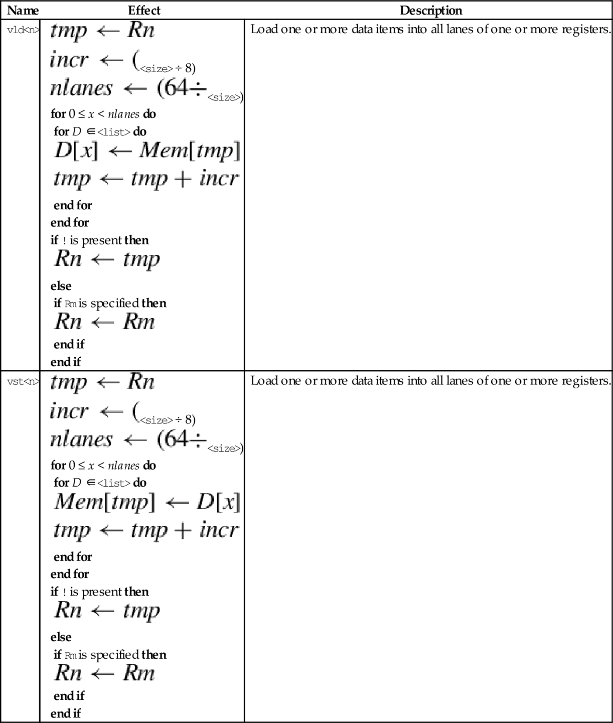
Operations
| Name | Effect | Description |
| vld<n> |
for 0 ≤ x < nlanes do for D ∈<list> do end for end for if ! is present then else if Rm is specified then end if end if | Load one or more data items into all lanes of one or more registers. |
| vst<n> |
for 0 ≤ x < nlanes do for D ∈<list> do end for end for if ! is present then else if Rm is specified then end if end if | Load one or more data items into all lanes of one or more registers. |
Examples
10.4 Data Movement Instructions
Because they use the same set of registers, VFP and NEON share some instructions for loading, storing, and moving registers. The shared instructions are vldr, vstr, vldm, vstm, vpop, vpush, vmov, vmrs, and vmsr. These were explained in Chapter 9. NEON extends the vmov instructions to allow specification of NEON scalars and quadwords, and adds the ability to perform one’s complement during a move.
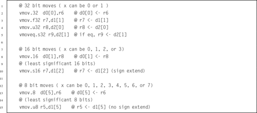
10.4.1 Moving Between NEON Scalar and Integer Register
This version of the move instruction allows data to be moved between the NEON registers and the ARM integer registers as 8-bit, 16-bit, or 32-bit NEON scalars:
vmov Move Between NEON and ARM.
Syntax
• <cond> is an optional condition code.
• <size> must be 8, 16, or 32, and specifies the number of bits that are to be moved.
• The <type> must be u8, u16, u32, s8, s16, s32, or f32, and specifies the number of bits that are to be moved and whether or not the result should be sign-extended in the ARM integer destination register.
Operations


Examples
10.4.2 Move Immediate Data
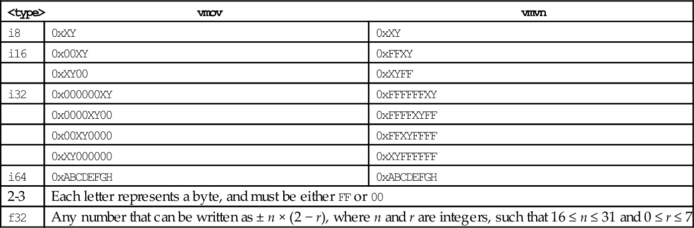
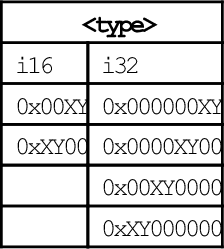
NEON extends the VFP vmov instruction to include the ability to move an immediate value, or the one’s complement of an immediate value, to every element of a register. The instructions are:
vmvn Move Immediate NOT.
Syntax
• <op> must be either <mov> or <mvn>.
• <type> must be i8, i16, i32, f32, or i64, and specifies the size of items in the vector.
• V can be s, d, or q.
• <imm> is an immediate value that matches <type>, and is copied to every element in the vector. The following table shows valid formats for imm:
| <type> | vmov | vmvn |
| i8 | 0xXY | 0xXY |
| i16 | 0x00XY | 0xFFXY |
| 0xXY00 | 0xXYFF | |
| i32 | 0x000000XY | 0xFFFFFFXY |
| 0x0000XY00 | 0xFFFFXYFF | |
| 0x00XY0000 | 0xFFXYFFFF | |
| 0xXY000000 | 0xXYFFFFFF | |
| i64 | 0xABCDEFGH | 0xABCDEFGH |
| 2-3 | Each letter represents a byte, and must be either FF or 00 | |
| f32 | Any number that can be written as ± n × (2 − r), where n and r are integers, such that 16 ≤ n ≤ 31 and 0 ≤ r ≤ 7 | |
Operations


Examples

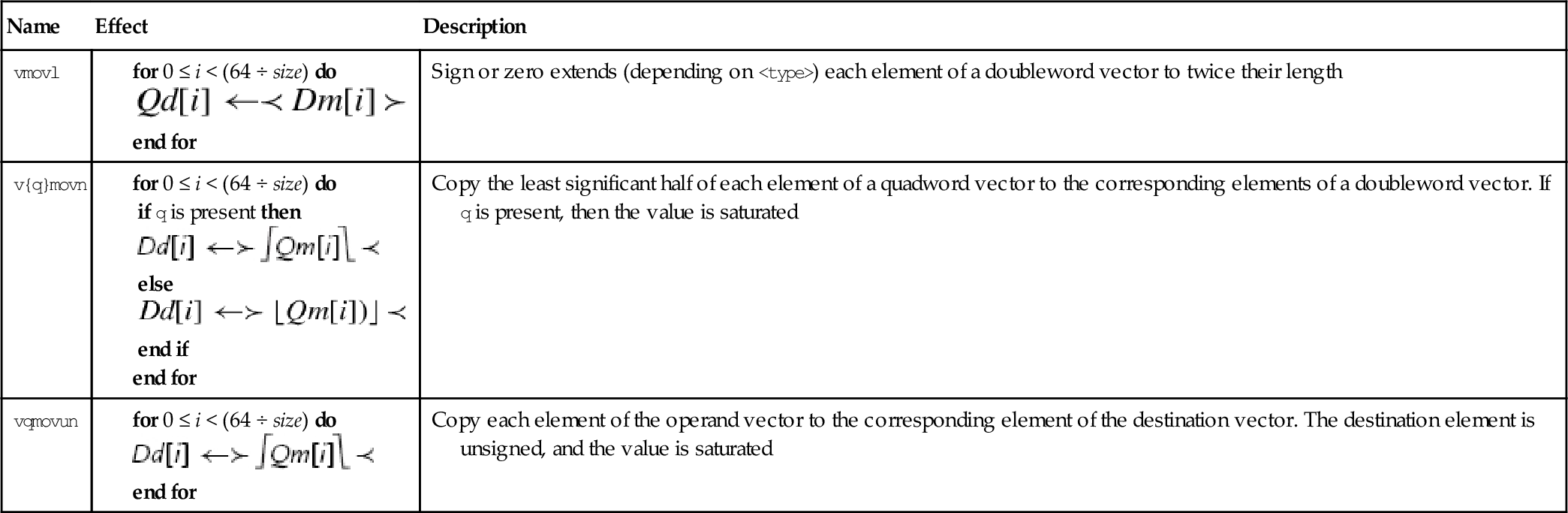
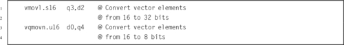
10.4.3 Change Size of Elements in a Vector
It is sometimes useful to increase or decrease the number of bits per element in a vector. NEON provides these instructions to convert a doubleword vector with elements of size y to a quadword vector with size 2y, or to perform the inverse operation:
vmovn Move and Narrow,
vqmovn Saturating Move and Narrow, and
vqmovun Saturating Move and Narrow Unsigned.
Syntax
• The valid choices for <type> are given in the following table:
| Opcode | Valid Types |
| vmovl | s8, s16, s32, u8, u16, or u32 |
| vmovn | i8, i16, or i32 |
| vqmovn | s8, s16, s32, u8, u16, or u32 |
| vqmovun | s8, s16, or s32 |
• q indicates that the results are saturated.
Operations
| Name | Effect | Description |
| vmovl |
end for | Sign or zero extends (depending on <type>) each element of a doubleword vector to twice their length |
| v{q}movn |
if q is present then else end if end for | Copy the least significant half of each element of a quadword vector to the corresponding elements of a doubleword vector. If q is present, then the value is saturated |
| vqmovun |
end for | Copy each element of the operand vector to the corresponding element of the destination vector. The destination element is unsigned, and the value is saturated |


Examples
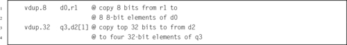
10.4.4 Duplicate Scalar
The duplicate instruction copies a scalar into every element of the destination vector. The scalar can be in a NEON register or an ARM integer register. The instruction is:
Syntax
• <size> must be one of 8, 16 or 32.
• V can be d or q.
• Rm cannot be r15.
Operations
Examples
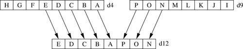
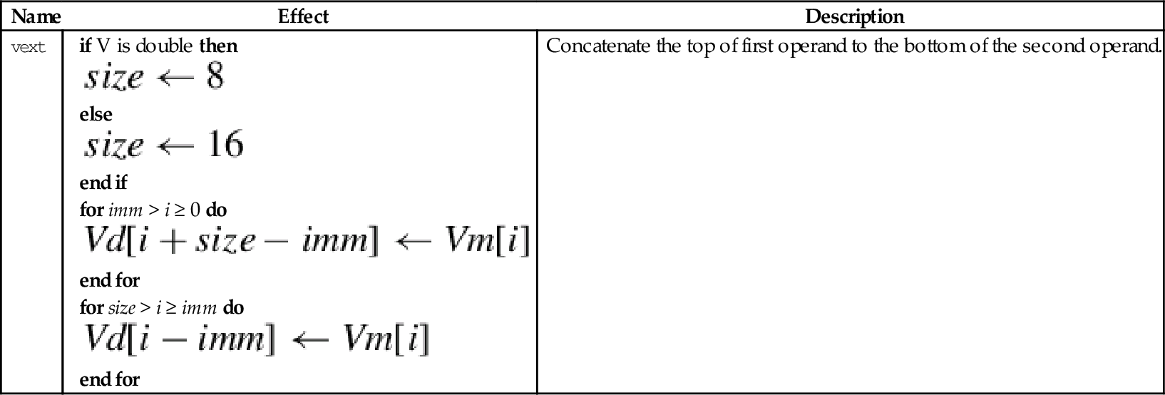
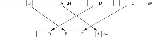
10.4.5 Extract Elements
This instruction extracts 8-bit elements from two vectors and concatenates them. Fig. 10.4 gives an example of what this instruction does. The instruction is:
Syntax
• <size> must be one of 8, 16, 32, or 64.
• V can be d or q.
• <imm> is the number of elements to extract from the bottom of Vm. The remaining elements required to fill Vd are taken from the top of Vn.
Operation


Examples

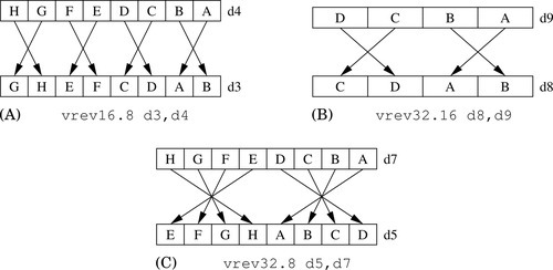
10.4.6 Reverse Elements
This instruction reverses the order of data in a register:
One use of this instruction is for converting data from big-endian to little-endian order, or from little-endian to big-endian order. It could also be useful for swapping data and transforming matrices. Fig. 10.5 shows three examples.
Syntax
• <size> is either 8, 16, or 32 and indicates the size of the elements to be reversed. <size> must be less than <n>.
• V can be q or d.
Operation


Examples

10.4.7 Swap Vectors
This instruction simply swaps two NEON registers:
Syntax
• <type> can be any NEON data type. The assembler ignores the type, but it can be useful to the programmer as extra documentation.
• V can be q or d.
Operation

Examples

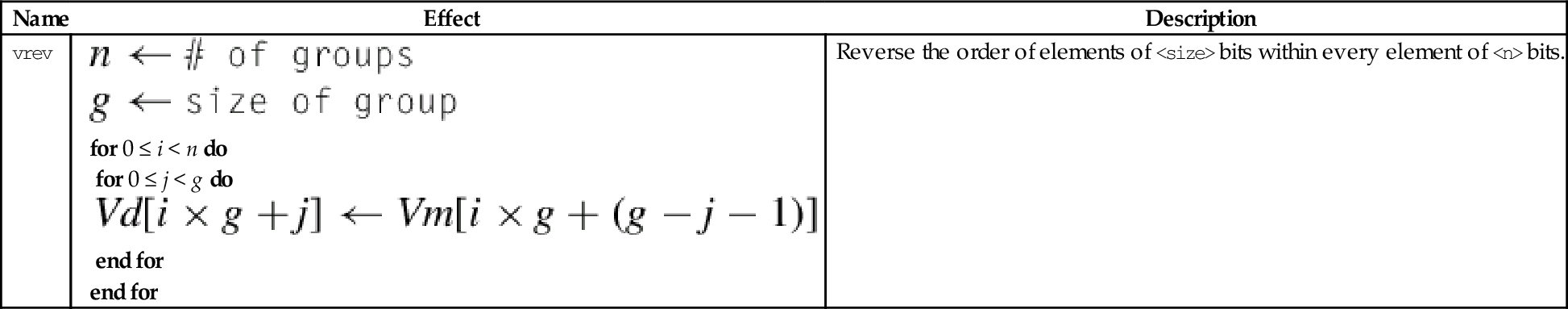
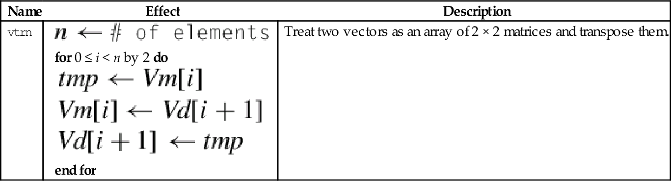
10.4.8 Transpose Matrix
This instruction transposes 2 × 2 matrices:
Fig. 10.6 shows two examples of this instruction. Larger matrices can be transposed using a divide-and-conquer approach.
Syntax
• <size> is either 8, 16, or 32 and indicates the size of the elements in the matrix (or matrices).
• V can be q or d.
Operation


Examples
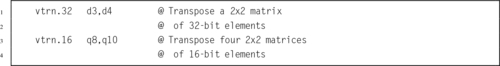
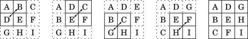
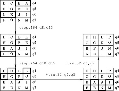
Fig. 10.7 shows how the vtrn instruction can be used to transpose a 3 × 3 matrix. Transposing a 4 × 4 matrix requires the transposition of 13 2 × 2 matrices. However, this instruction can operate on multiple 2 × 2 sub-matrices in parallel, and can group elements into different sized sub-matrices. There is also a very useful swap instruction that can exchange the rows of a matrix. Using the swap and transpose instructions, transposing a 4 × 4 matrix of 16-bit elements can be done with only four instructions, as shown in Fig. 10.8.
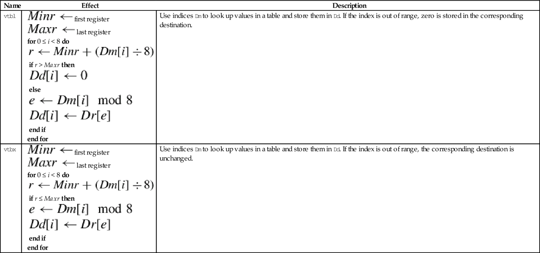
10.4.9 Table Lookup
The table lookup instructions use indices held in one vector to lookup values from a table held in one or more other vectors. The resulting values are stored in the destination vector. The table lookup instructions are:
vtbx Table Lookup with Extend.
Syntax
• <list> specifies the list of registers. There are five list formats:
2. {Dn, D(n+1)},
3. {Dn, D(n+1), D(n+2)},
4. {Dn, D(n+1), D(n+2), D(n+3)}, or
5. {Qn, Q(n+1)}.
• Dm is the register holding the indices.
• The table can contain up to 32 bytes.
Operations
| Name | Effect | Description |
| vtbl |
for 0 ≤ i < 8 do if r > Maxr then else end if end for | Use indices Dm to look up values in a table and store them in Dd. If the index is out of range, zero is stored in the corresponding destination. |
| vtbx |
for 0 ≤ i < 8 do if r ≤ Maxr then end if end for | Use indices Dm to look up values in a table and store them in Dd. If the index is out of range, the corresponding destination is unchanged. |


Examples

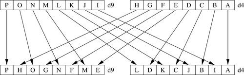
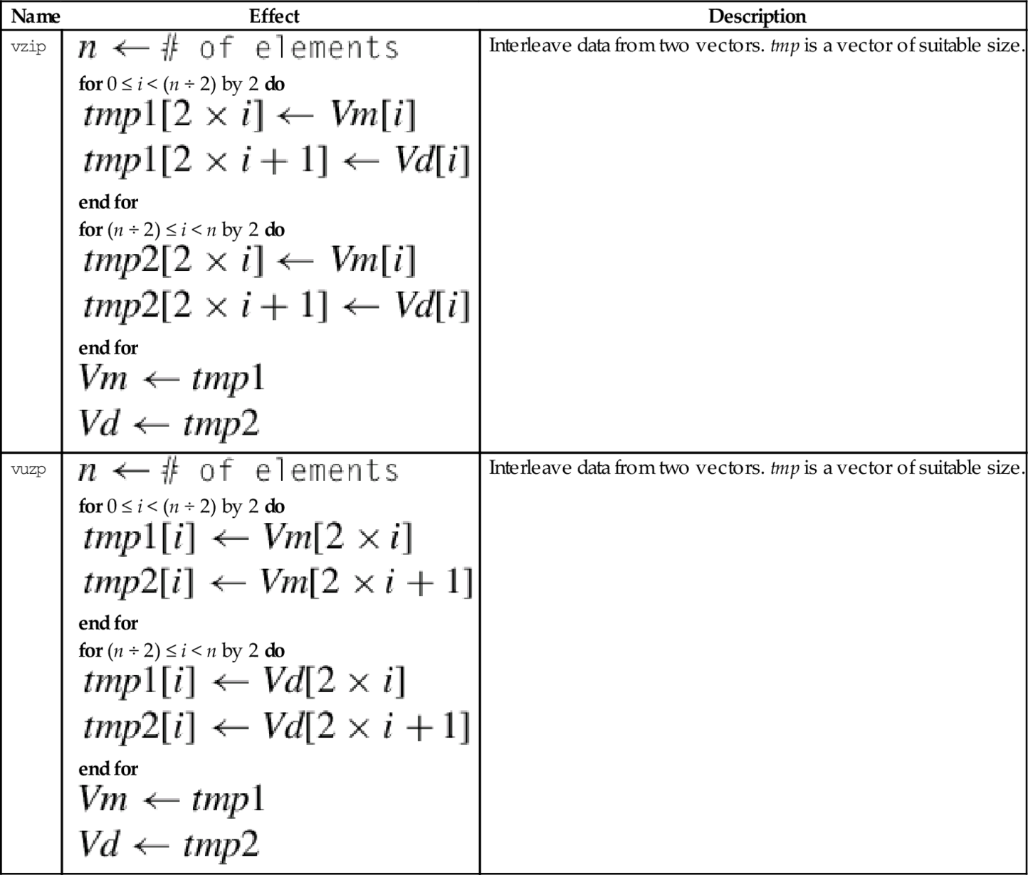
10.4.10 Zip or Unzip Vectors
These instructions are used to interleave or deinterleave the data from two vectors:
vuzp Unzip Vectors.
Fig. 10.9 gives an example of the vzip instruction. The vuzp instruction performs the inverse operation.
Syntax
• <size> is either 8, 16, or 32 and indicates the size of the elements in the matrix (or matrices).
• V can be q or d.
Operations
| Name | Effect | Description |
| vzip |
for 0 ≤ i < (n ÷ 2) by 2 do end for for (n ÷ 2) ≤ i < n by 2 do end for
| Interleave data from two vectors. tmp is a vector of suitable size. |
| vuzp |
for 0 ≤ i < (n ÷ 2) by 2 do end for for (n ÷ 2) ≤ i < n by 2 do end for
| Interleave data from two vectors. tmp is a vector of suitable size. |


Examples

10.5 Data Conversion
When high precision is not required, The IEEE half-precision format can be used to store floating point numbers in memory. This can reduce memory requirements by up to 50%. This can also result in a significant performance improvement, since only half as much data needs to be moved between the CPU and main memory. However, on most processors half-precision data must be converted to single precision before it is used in calculations. NEON provides enhanced versions of the vcvt instruction which support conversion to and from IEEE half precision. There are also versions of vcvt which operate on vectors, and perform integer or fixed-point to floating-point conversions.
10.5.1 Convert Between Fixed Point and Single-Precision
This instruction can be used to perform a data conversion between single precision and fixed point on each element in a vector:
The elements in the vector must be a 32-bit single precision floating point or a 32-bit integer. Fixed point (or integer) arithmetic operations are up to twice as fast as floating point operations. In some cases it is much more efficient to make this conversion, perform the calculations, then convert the results back to floating point.
Syntax
• <cond> is an optional condition code.
• <type> must be either s32 or u32.
• The optional <fbits> operand specifies the number of fraction bits for a fixed point number, and must be between 0 and 32. If it is omitted, then it is assumed to be zero.
Operations
| Name | Effect | Description |
| vcvt.s32.f32 |  | Convert single precision to 32-bit signed fixed point or integer. |
| vcvt.u32.f32 |  | Convert single precision to 32-bit unsigned fixed point or integer. |
| vcvt.f32.s32 |  | Convert signed 32-bit fixed point or integer to single precision |
| vcvt.f32.u32 | | Convert unsigned 32-bit fixed point or integer to single precision |
Examples

10.5.2 Convert Between Half-Precision and Single-Precision
NEON systems with the half-precision extension provide the following instruction to perform conversion between single precision and half precision floating point formats:
vcvt Convert Between Half and Single.
Syntax
• The <op> must be either b or t and specifies whether the top or bottom half of the register should be used for the half-precision number.
• <cond> is an optional condition code.
Operations
| Name | Effect | Description |
| vcvtb.f16.f32 |  | Convert single precision to half precision and store in bottom half of destination |
| vcvtt.f16.f32 | | Convert single precision to half precision and store in top half of destination |
| vcvtb.f32.f16 |  | Convert half precision number from bottom half of source to single precision |
| vcvtt.f32.f16 | | Convert half precision number from top half of source to single precision |
Examples

10.6 Comparison Operations
NEON adds the ability to perform integer comparisons between vectors. Since there are multiple pairs of items to be compared, the comparison instructions set one element in a result vector for each pair of items. After the comparison operation, each element of the result vector will have every bit set to zero (for false) or one (for true). Note that if the elements of the result vector are interpreted as signed two’s-complement numbers, then the value 0 represents false and the value − 1 represents true.
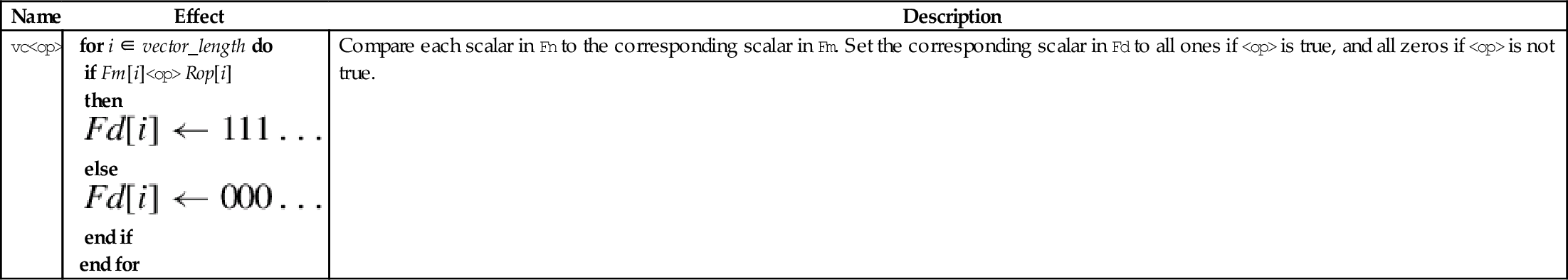
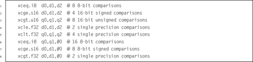
10.6.1 Vector Compare
The following instructions perform comparisons of all of the corresponding elements of two vectors in parallel:
vcge Compare Greater Than or Equal,
vcgt Compare Greater Than,
vcle Compare Less Than or Equal, and
vclt Compare Less Than.
The vector compare instructions compare each element of a vector with the corresponding element in a second vector, and sets an element in the destination vector for each comparison. If the comparison is true, then all bits in the result element are set to one. Otherwise, all bits in the result element are set to zero. Note that summing the elements of the result vector (as signed integers) will give the two’s complement of the number of comparisons which were true.
Note: vcle and vclt are actually pseudo-instructions. They are equivalent to vcgt and vcge with the operands reversed.
Syntax
• <op> must be one of eq, ge, gt, le, or lt.
• If <op> is eq, then <type> must be i8, i16, i32, or f32.
• If <op> is not eq and Rop is #0, then < type > must be s8, s16, s32, or f32.
• If <op> is not eq and the third operand is a register, then <type> must be s8, s16, s32, u8, u16, u32, or f32.
• The result data type is determined from the following table:
• If the third operand is #0, then it is taken to be a vector of the correct size in which every element is zero.
• V can be d or q.
Operations


Examples
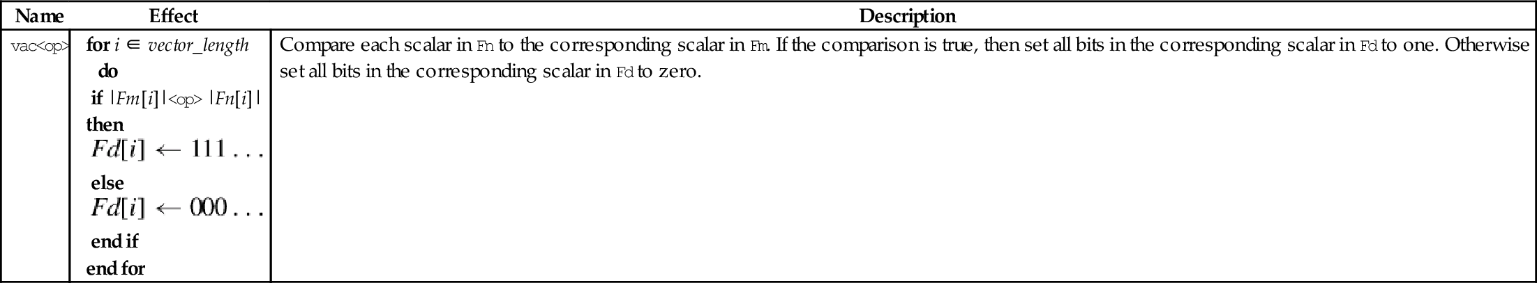
10.6.2 Vector Absolute Compare
The following instructions perform comparisons between the absolute values of all of the corresponding elements of two vectors in parallel:
vacgt Absolute Compare Greater Than, and
vacge Absolute Compare Greater Than or Equal.
The vector absolute compare instruction compares the absolute value of each element of a vector with the absolute value of the corresponding element in a second vector, and sets an element in the destination vector for each comparison. If the comparison is true, then all bits in the result element are set to one. Otherwise, all bits in the result element are set to zero. Note that summing the elements of the result vector (as signed integers) will give the two’s complement of the number of comparisons which were true.
Syntax
• <op> must be either ge or gt.
• V can be d or q.
• The operand element type must be f32.
• The result element type is i32.
Operations
Examples

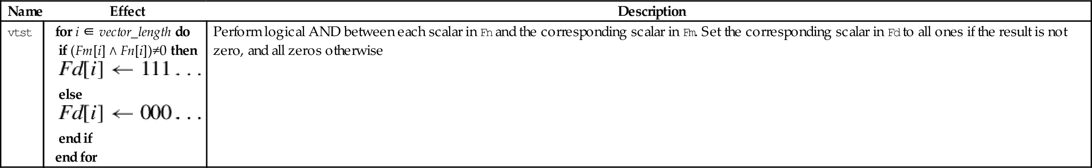
10.6.3 Vector Test Bits
NEON provides the following vector version of the ARM tst instruction:
The vector test bits instruction performs a logical AND operation between each element of a vector and the corresponding element in a second vector. If the result is not zero, then every bit in the corresponding element of the result vector is set to one. Otherwise, every bit in the corresponding element of the result vector is set to zero.
Syntax
• <size> must be one of 8, 16 or 32
• The result element type is defined by the following table:
Operations
Examples

10.7 Bitwise Logical Operations
NEON adds the ability to perform integer and bitwise logical operations on the VFP register set. Recall that integer operations can also be used on fixed-point data. These operations add a great deal of power to the ARM processor.
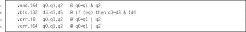
10.7.1 Bitwise Logical Operations
NEON includes vector versions of the following five basic logical operations:
veor Bitwise Exclusive-OR,
vorr Bitwise OR,
vorn Bitwise Complement and OR, and
vbic Bit Clear.
All of them involve two source operands and a destination register.
Syntax
• <op> must be one of and, eor, orr, orn, or bic.
• V must be either q or d.
• type must be i8, i16, i32, or i64. For these bitwise logical operations, type does not matter.
Operations


Examples
10.7.2 Bitwise Logical Operations with Immediate Data
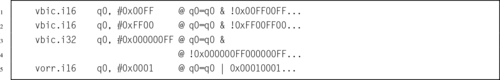
It is often useful to clear and/or set specific bits in a register. The NEON instruction set provides the following vector versions of the logical OR and bit clear instructions:
vorr Bitwise OR Immediate, and
vbic Bit Clear Immediate.
Syntax
• <op> must be either orr, or bic.
• V must be either q or d to specify whether the operation involves quadwords or doublewords.
• <type> must be i16 or i32.
• <imm> is a 16-bit or 32-bit immediate value, which is interpreted as a pattern for filling the immediate operand. The following table shows acceptable patterns for <imm>, based on what was chosen for <type>:
Operations


Examples
10.7.3 Bitwise Insertion and Selection
NEON provides three instructions which can be used to combine the bits in two registers or to extract specific bits from a register, according to a pattern:
vbif Bitwise Insert if False, and
vbsl Bitwise Select.
Syntax
• <op> can be bif, bit, or bsl.
• V can be d or q.
• The <type> must be i8, i16, i32, or i64, and specifies the size of items in the vectors. Note that for these bitwise logical operations, the type does not matter. so the assembler ignores it. However, it can be useful to the programmer as extra documentation.
Operations
| Name | Effect | Description |
| vbit |  | Insert each bit from the first operand into the destination if the corresponding bit of the second operand is 1 |
| vbif |  | Insert each bit from the first operand into the destination if the corresponding bit of the second operand is 0 |
| vbsl |  | Select each bit for the destination from the first operand if the corresponding bit of the destination is 1, or from the second operand if the corresponding bit of the destination is 0 |
Examples

10.8 Shift Instructions
The NEON shift instructions operate on vectors. Shifts are often used for multiplication and division by powers of two. The results of a left shift may be larger than the destination register, resulting in overflow. A shift right is equivalent to division. In some cases, it may be useful to round the result of a division, rather than truncating. NEON provides versions of the shift instruction which perform saturation and/or rounding of the result.
10.8.1 Shift Left by Immediate
These instructions shift each element in a vector left by an immediate value:
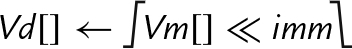
vqshl Saturating Shift Left Immediate,
vqshlu Saturating Shift Left Immediate Unsigned, and
vshll Shift Left Immediate Long.
Overflow conditions can be avoided by using the saturating version, or by using the long version, in which case the destination is twice the size of the source.
Syntax
• If u is present, then the results are unsigned.
• The valid choices for <type> are given in the following table:
Operations
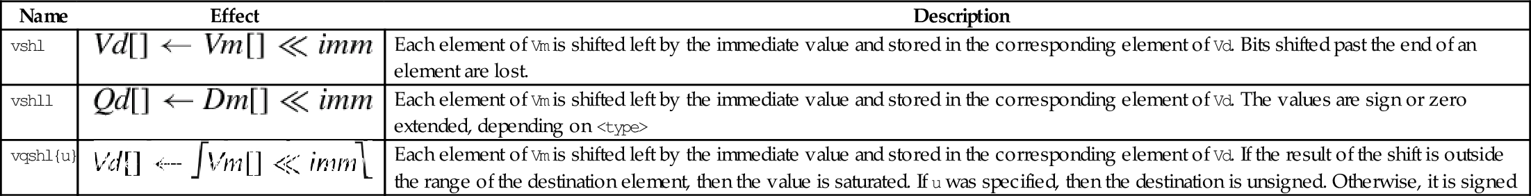
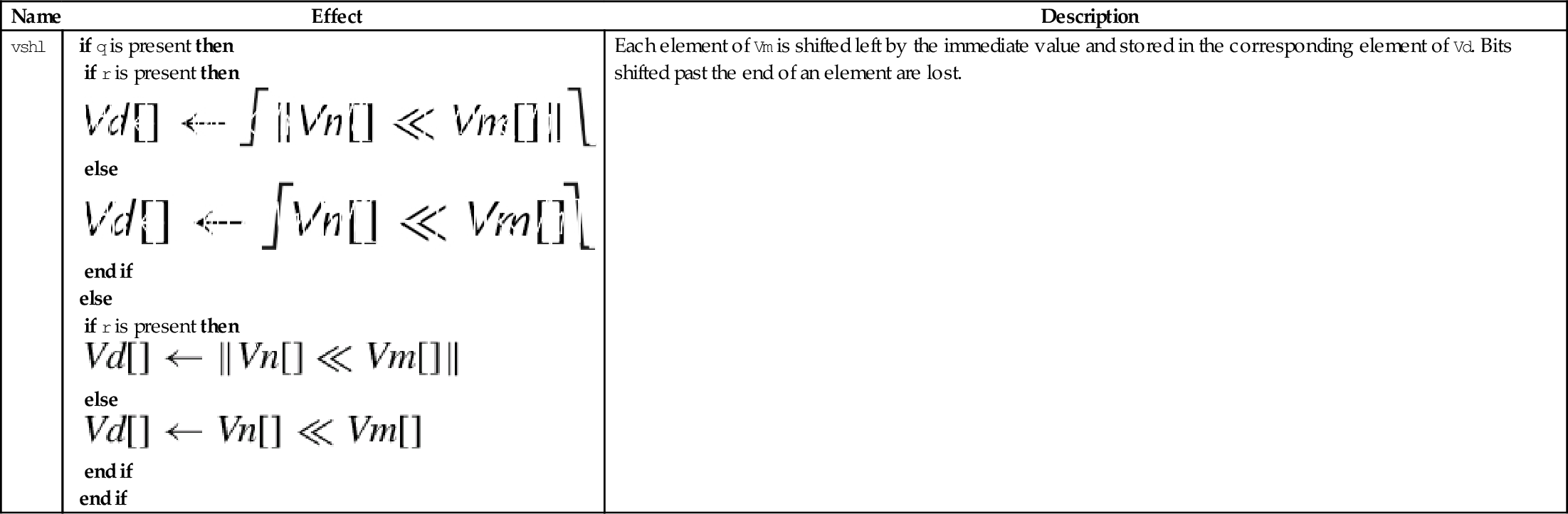
| Name | Effect | Description |
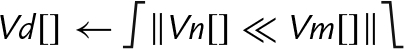
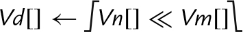
| vshl | Each element of Vm is shifted left by the immediate value and stored in the corresponding element of Vd. Bits shifted past the end of an element are lost. | |
| vshll | Each element of Vm is shifted left by the immediate value and stored in the corresponding element of Vd. The values are sign or zero extended, depending on <type> | |
| vqshl{u} | Each element of Vm is shifted left by the immediate value and stored in the corresponding element of Vd. If the result of the shift is outside the range of the destination element, then the value is saturated. If u was specified, then the destination is unsigned. Otherwise, it is signed |


Examples

10.8.2 Shift Left or Right by Variable
These instructions shift each element in a vector, using the least significant byte of the corresponding element of a second vector as the shift amount:
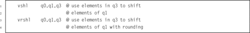
vshl Shift Left or Right by Variable,
vrshl Shift Left or Right by Variable and Round,
vqshl Saturating Shift Left or Right by Variable, and
vqrshl Saturating Shift Left or Right by Variable and Round.
If the shift value is positive, the operation is a left shift. If the shift value is negative, then it is a right shift. A shift value of zero is equivalent to a move. If the operation is a right shift, and r is specified, then the result is rounded rather than truncated. Results are saturated if q is specified.
Syntax
• If q is present, then the results are saturated.
• If r is present, then right shifted values are rounded rather than truncated.
• V can be d or q.
• <type> must be one of s8, s16, s32, s64, s8, s16, s32, or s64.
Operations


Examples
10.8.3 Shift Right by Immediate
These instructions shift each element in a vector right by an immediate value:
vrshr Shift Right Immediate and Round,
vshrn Shift Right Immediate and Narrow,
vrshrn Shift Right Immediate Round and Narrow,
vsra Shift Right and Accumulate Immediate, and
vrsra Shift Right Round and Accumulate Immediate.
Syntax
• If r is present, then right shifted values are rounded rather than truncated.
• <cond> is an optional condition code.
• The valid choices for <type> are given in the following table:
Operations
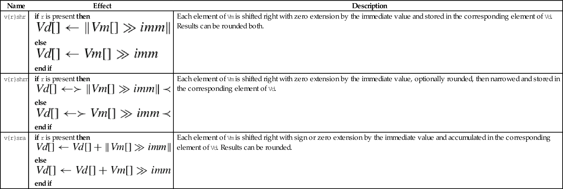
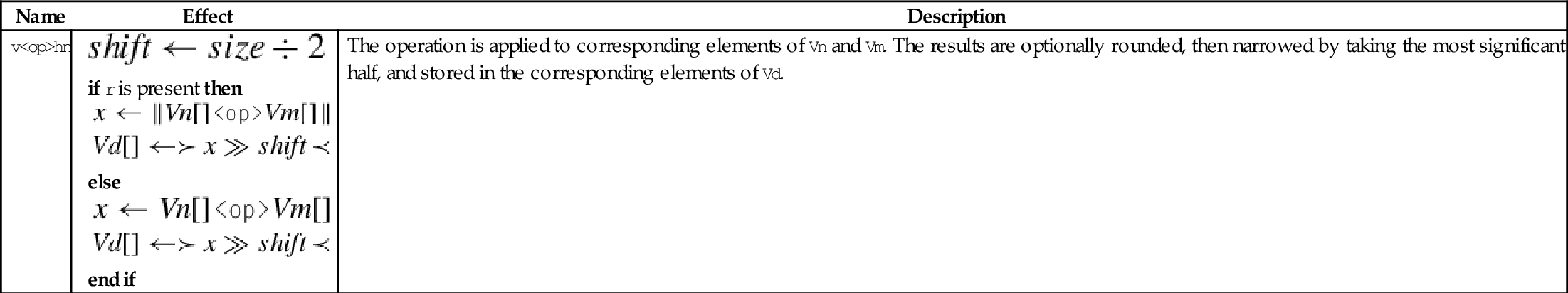
| Name | Effect | Description |
| v{r}shr |
else end if | Each element of Vm is shifted right with zero extension by the immediate value and stored in the corresponding element of Vd. Results can be rounded both. |
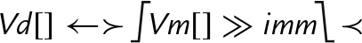
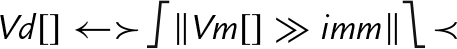
| v{r}shrn |
else end if | Each element of Vm is shifted right with zero extension by the immediate value, optionally rounded, then narrowed and stored in the corresponding element of Vd. |
| v{r}sra |
else end if | Each element of Vm is shifted right with sign or zero extension by the immediate value and accumulated in the corresponding element of Vd. Results can be rounded. |


Examples

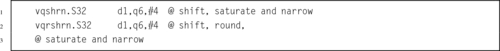
10.8.4 Saturating Shift Right by Immediate
These instructions shift each element in a quad word vector right by an immediate value:
vqshrn Saturating Shift Right Immediate,
vqrshrn Saturating Shift Right Immediate Round,
vqshrun Saturating Shift Right Immediate Unsigned, and
vqrshrun Saturating Shift Right Immediate Round Unsigned.
The result is optionally rounded, then saturated, narrowed, and stored in a double word vector.
Syntax
• If r is present, then right shifted values are rounded rather than truncated.
• If u is present, then the results are unsigned, regardless of the type of elements in Qm.
• The valid choices for <type> are given in the following table:
• <imm> Is the amount that elements are to be shifted, and must be between zero and one less than the number of bits in <type>.
Operations
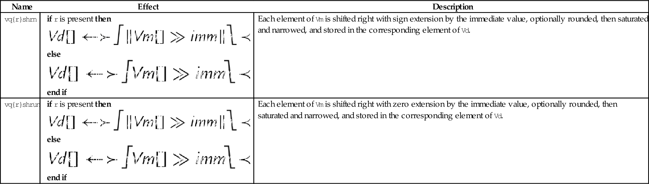
| Name | Effect | Description |
| vq{r}shrn |
else end if | Each element of Vm is shifted right with sign extension by the immediate value, optionally rounded, then saturated and narrowed, and stored in the corresponding element of Vd. |
| vq{r}shrun |
else end if | Each element of Vm is shifted right with zero extension by the immediate value, optionally rounded, then saturated and narrowed, and stored in the corresponding element of Vd. |


Examples
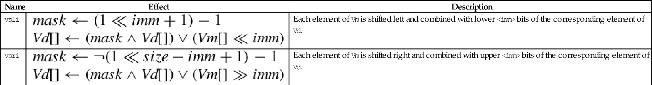
10.8.5 Shift and Insert
These instructions perform bitwise shifting of each element in a vector, then combine the results with the contents of the destination register:
vsri Shift Right and Insert.
Fig. 10.10 provides an example.
Syntax
• <dir> must be l for a left shift, or r for a right shift.
• <size> must be 8, 16, 32, or 64.
• <imm> is the amount that elements are to be shifted, and must be between zero and <size>− 1 for vsli, or between one and <size> for vsri.
Operations


Examples

10.9 Arithmetic Instructions
NEON provides several instructions for addition, subtraction, and multiplication, but does not provide a divide instruction. Whenever possible, division should be performed by multiplying the reciprocal. When dividing by constants, the reciprocal can be calculated in advance, as shown in Chapter 8. For dividing by variables, NEON provides instructions for quickly calculating the reciprocals for all elements in a vector. In most cases, this is faster than using a divide instruction. When division is absolutely unavoidable, the VFP divide instructions can be used.
10.9.1 Vector Add and Subtract
The following eight instructions perform vector addition and subtraction:
vqadd Saturating Add
vaddl Add Long
vaddw Add Wide
vsub Subtract
vqsub Saturating Subtract
vsubl Subtract Long
vsubw Subtract Wide
The Vector Add (vadd) instruction adds corresponding elements in two vectors and stores the results in the corresponding elements of the destination register. The Vector Subtract (vsub) instruction subtracts elements in one vector from corresponding elements in another vector and stores the results in the corresponding elements of the destination register. Other versions allow mismatched operand and destination sizes, and the saturating versions prevent overflow by limiting the range of the results.
Syntax
• The valid choices for <type> are given in the following table:
Operations
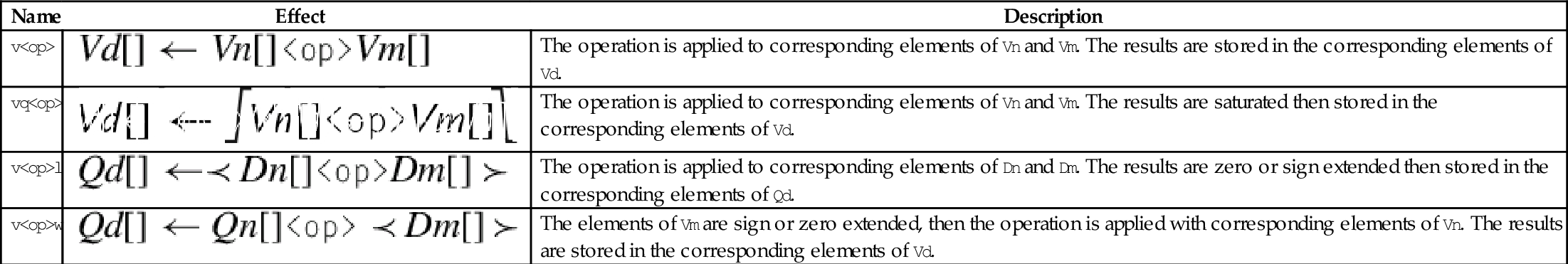
| Name | Effect | Description |
| v<op> | The operation is applied to corresponding elements of Vn and Vm. The results are stored in the corresponding elements of Vd. | |
| vq<op> | The operation is applied to corresponding elements of Vn and Vm. The results are saturated then stored in the corresponding elements of Vd. | |
| v<op>l | The operation is applied to corresponding elements of Dn and Dm. The results are zero or sign extended then stored in the corresponding elements of Qd. | |
| v<op>w | The elements of Vm are sign or zero extended, then the operation is applied with corresponding elements of Vn. The results are stored in the corresponding elements of Vd. |


Examples

10.9.2 Vector Add and Subtract with Narrowing
These instructions add or subtract the corresponding elements of two vectors, and narrow by taking the most significant half of the result:
vraddhn Add, Round, and Narrow
vsubhn Subtract and Narrow
vrsubhn Subtract, Round, and Narrow
The results are stored in the corresponding elements of the destination register. Results can be optionally rounded instead of truncated.
Syntax
• If <r> is specified, then the result is rounded instead of truncated.
• <type> must be either i16, i32, or i64.
Operations


Examples

10.9.3 Add or Subtract and Divide by Two
These instructions add or subtract corresponding elements from two vectors then shift the result right by one bit:
vrhadd Halving Add and Round
vhsub Halving Subtract
The results are stored in corresponding elements of the destination vector. If the operation is addition, then the results can be optionally rounded.
Syntax
• If <r> is specified, then the result is rounded instead of truncated.
• <type> must be either s8, s16, s32, u8, u16, ar u32.
Operations
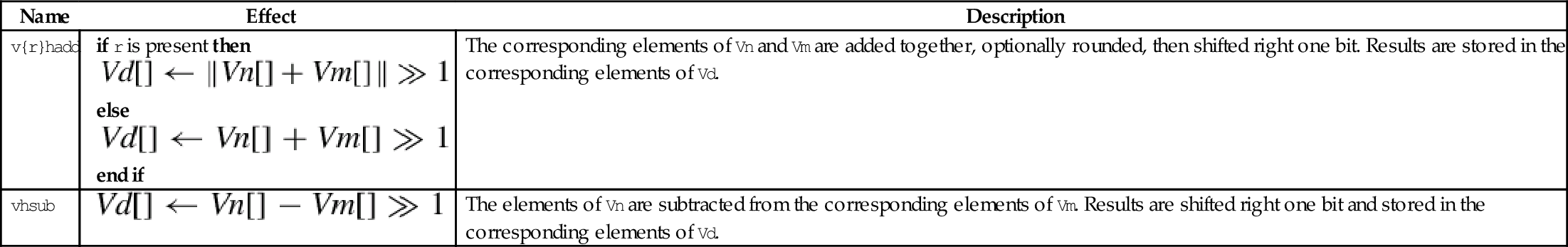
| Name | Effect | Description |
| v{r}hadd |
else end if | The corresponding elements of Vn and Vm are added together, optionally rounded, then shifted right one bit. Results are stored in the corresponding elements of Vd. |
| vhsub | The elements of Vn are subtracted from the corresponding elements of Vm. Results are shifted right one bit and stored in the corresponding elements of Vd. |


Examples

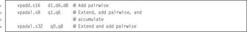
10.9.4 Add Elements Pairwise
These instructions add vector elements pairwise:
vpaddl Add Pairwise Long
vpadal Add Pairwises and Accumulate Long
The long versions can be used to prevent overflow.
Syntax
• <op> must be either add or ada.
• The valid choices for <type> are given in the following table:
Operations
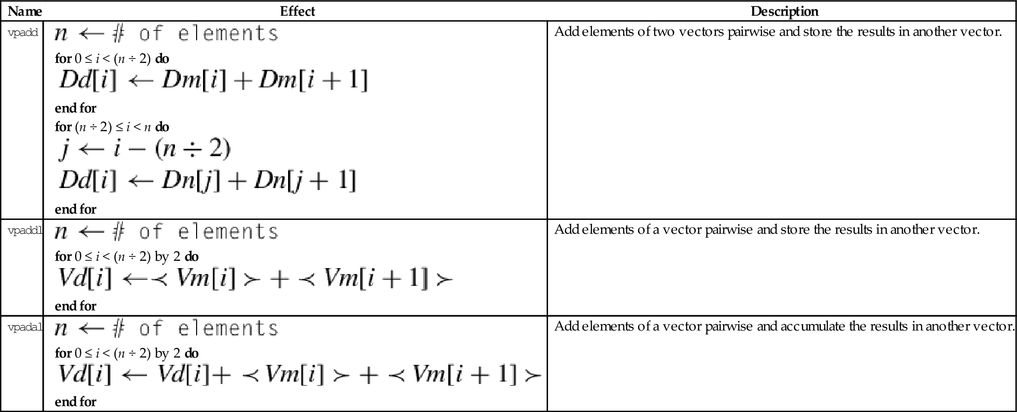
| Name | Effect | Description |
| vpadd |
for 0 ≤ i < (n ÷ 2) do end for for (n ÷ 2) ≤ i < n do end for | Add elements of two vectors pairwise and store the results in another vector. |
| vpaddl |
for 0 ≤ i < (n ÷ 2) by 2 do end for | Add elements of a vector pairwise and store the results in another vector. |
| vpadal |
for 0 ≤ i < (n ÷ 2) by 2 do end for | Add elements of a vector pairwise and accumulate the results in another vector. |


Examples
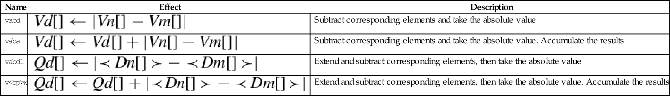
10.9.5 Absolute Difference
These instructions subtract the elements of one vector from another and store or accumulate the absolute value of the results:
vaba Absolute Difference and Accumulate
vabal Absolute Difference and Accumulate Long
vabd Absolute Difference
vabdl Absolute Difference Long
The long versions can be used to prevent overflow.
Syntax
• The valid choices for <type> are given in the following table:
Operations
| Name | Effect | Description |
| vabd | Subtract corresponding elements and take the absolute value | |
| vaba | Subtract corresponding elements and take the absolute value. Accumulate the results | |
| vabdl | Extend and subtract corresponding elements, then take the absolute value | |
| v<op>w | Extend and subtract corresponding elements, then take the absolute value. Accumulate the results |


Examples

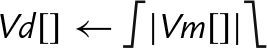
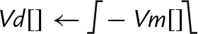
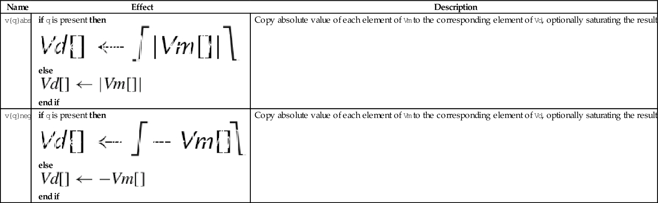
10.9.6 Absolute Value and Negate
These operations compute the absolute value or negate each element in a vector:
vneg Negate
vqabs Saturating Absolute Value
vqneg Saturating Negate
The saturating versions can be used to prevent overflow.
Syntax
• If q is present then results are saturated.
• <op> is either abs or neg.
• The valid choices for <type> are given in the following table:
Operations


Examples

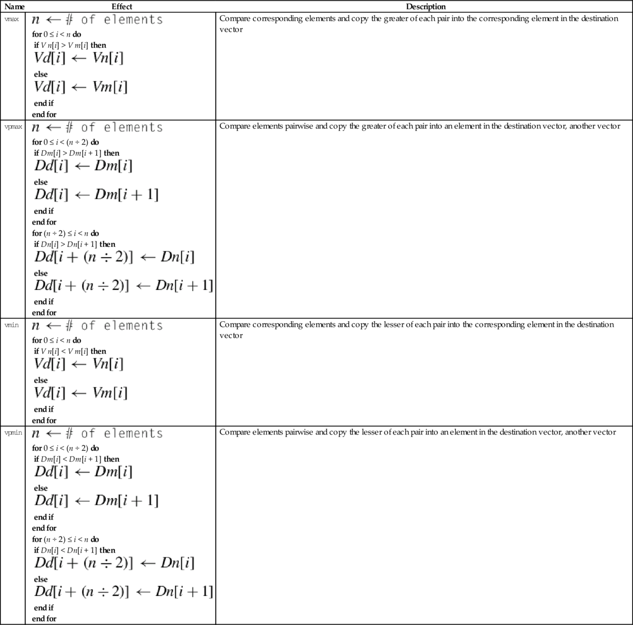
10.9.7 Get Maximum or Minimum Elements
The following four instructions select the maximum or minimum elements and store the results in the destination vector:
vmin Minimum
vpmax Pairwise Maximum
vpmin Pairwise Minimum
Syntax
• <type> must be one of s8, s16, s32, u8, u16, u32, or f32.
Operations
| Name | Effect | Description |
| vmax |
for 0 ≤ i < n do if V n[i] > V m[i] then else end if end for | Compare corresponding elements and copy the greater of each pair into the corresponding element in the destination vector |
| vpmax |
for 0 ≤ i < (n ÷ 2) do if Dm[i] > Dm[i + 1] then else end if end for for (n ÷ 2) ≤ i < n do if Dn[i] > Dn[i + 1] then else end if end for | Compare elements pairwise and copy the greater of each pair into an element in the destination vector, another vector |
| vmin |
for 0 ≤ i < n do if V n[i] < V m[i] then else end if end for | Compare corresponding elements and copy the lesser of each pair into the corresponding element in the destination vector |
| vpmin |
for 0 ≤ i < (n ÷ 2) do if Dm[i] < Dm[i + 1] then else end if end for for (n ÷ 2) ≤ i < n do if Dn[i] < Dn[i + 1] then else end if end for | Compare elements pairwise and copy the lesser of each pair into an element in the destination vector, another vector |


Examples
