Table of Contents for
Modern Assembly Language Programming with the ARM Processor
 Modern Assembly Language Programming with the ARM Processor
Published by
Newnes, 2016
Modern Assembly Language Programming with the ARM Processor
Published by
Newnes, 2016
- Modern Assembly Language Programming with the ARM Processor
- Cover image
- Title page
- Table of Contents
- Copyright
- List of Tables
- List of Figures
- List of Listings
- Preface
- Companion Website
- Acknowledgments
- Part I: Assembly as a Language
- Chapter 1: Introduction
- Chapter 2: GNU Assembly Syntax
- Chapter 3: Load/Store and Branch Instructions
- Chapter 4: Data Processing and Other Instructions
- Chapter 5: Structured Programming
- Chapter 6: Abstract Data Types
- Part II: Performance Mathematics
- Chapter 7: Integer Mathematics
- Chapter 8: Non-Integral Mathematics
- Chapter 9: The ARM Vector Floating Point Coprocessor
- Chapter 10: The ARM NEON Extensions
- 10.10 Multiplication and Division
- Part III: Accessing Devices
- Chapter 11: Devices
- Chapter 12: Pulse Modulation
- Chapter 13: Common System Devices
- Chapter 14: Running Without an Operating System
- Index
The ARM Vector Floating Point Coprocessor
Abstract
This chapter begins by giving an overview of the ARM Vector Floating Point (VFP) coprocessor and the ARM VFP register set. Next, it gives an overview of the Floating Point Status and Control Register (FPSCR). It then explains RunFast mode, which gives higher performance but is not fully compliant with the IEEE floating point standards. That is followed by a explanation of vector mode, which can give an additional performance boost in some situations. Then, after a short discussion of the register usage rules, it describes each of the VFP instructions, providing a short description of each one. Next, it presents four implementations of a function to calculate sine using the ARM VFP coprocessor, and shows that they are all significantly faster than the implementation provided by GCC.
Keywords
Floating point; Vector; IEEE Compliance; Performance
Some ARM processors have dedicated hardware to support floating point operations. For ARMv7 and previous architectures, floating point is provided by an optional Vector Floating Point (VFP) coprocessor. Many newer processors also support the NEON extensions, which are covered in Chapter 10. The remainder of this chapter will explain the VFP coprocessor.
9.1 Vector Floating Point Overview
There are four major revisions of the VFP coprocessor:
VFPv2: An optional extension to the ARMv5 and ARMv6 processors. VFPv2 has 16 64-bit FPU registers.
VFPv3: An optional extension to the ARMv7 processors. It is backwards compatible with VFPv2, except that it cannot trap floating-point exceptions. VFPv3-D32 has 32 64-bit FPU registers. Some processors have VFPv3-D16, which supports only 16 64-bit FPU registers. VFPv3 adds several new instructions to the VFP instruction set.
VFPv4: Implemented on some Cortex ARMv7 processors. VFPv4 has 32 64-bit FPU registers. It adds both half-precision extensions and multiply-accumulate instructions to the features of VFPv3. Some processors have VFPv4-D16, which supports only 16 64-bit FPU registers.
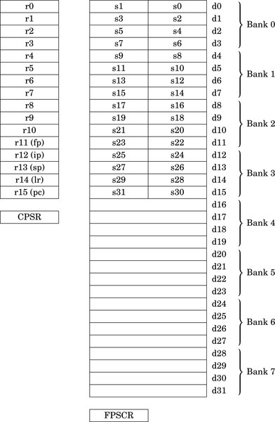
Fig. 9.1 shows the 16 ARM integer registers, and the additional registers provided by the VFP coprocessor. Banks four through seven are only present on the VFPv3-D32 and VFPv4-D32 versions of the coprocessor. Note that each register in Banks zero through three can be used to store either one 64-bit number or two 32-bit numbers. For example, double precision register d0 may also be referred to as single precision registers s0 and s1. Each 32-bit VFP register can hold an integer or a single precision floating point number. Registers in Banks four through seven cannot be used as single precision registers.
The VFP adds about 23 new instructions to the ARM instruction set. The exact number of VFP instructions depends on the specific version of the VFP coprocessor. Instructions are provided to:
• transfer floating point values between VFP registers,
• transfer floating-point values between the VFP coprocessor registers and main memory,
• transfer 32-bit values between the VFP coprocessor registers and the ARM integer registers,
• perform addition, subtraction, multiplication, and division, involving two source registers and a destination register,
• compute the square root of a value,
• perform combined multiply-accumulate operations,
• perform conversions between various integer, fixed point, and floating point representations, and
• compare floating-point values.
In addition to performing basic operations involving two source registers and one destination register, VFP instructions can also perform operations involving registers arranged as short vectors (arrays) of up to eight single-precision values or four double-precision values. A single instruction can be used to perform operations on all of the elements of such vectors. This feature can substantially accelerate computation on arrays and matrices of floating point data. This type of data is common in graphics and signal processing applications. Vector mode can reduce code size and increase speed of execution by supporting parallel operations and multiple transfers.
9.2 Floating Point Status and Control Register
The Floating Point Status and Control Register (FPSCR) is similar to the CPSR register. The FPSCR stores status bits from floating point operations in much the same way as the CPSR stores status bits from integer operations. The programmer can also write to certain bits in the FPSCR to control the behavior of the VFP coprocessor. The layout of the FPSCR is shown in Fig. 9.2. The meaning of each field is as follows:
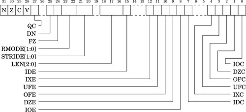
N The Negative flag is set to one by vcmp if Fd < Fm.
Z The Zero flag is Set to one by vcmp if Fd = Fm.
C The Carry flag is set to one by vcmp if Fd = Fm, or Fd > Fm, or Fd and Fm are unordered.
V The oVerflow flag is set to one by vcmp if Fd and Fm are unordered.
QC NEON only. The saturation cumulative flag is set to one by saturating instructions if saturation has occurred.
0: Disable Default NaN mode. NaN operands propagate through to the output of a floating-point operation.
1: Enable Default NaN mode. Any operation involving one or more NaNs returns the default NaN.
The default single precision NaN is 7FC0000016 and the default double-precision NaN is 7FF800000000000016. Default NaN mode does not comply with IEEE 754 standard, but may increase performance. NEON instructions ignore this bit and always use Default NaN mode.
0: Disable Flush-to-Zero mode.
1: Enable Flush-to-Zero mode.
Flush-to-Zero mode replaces subnormal numbers with 0. This does not comply with IEEE 754 standard, but may increase performance. NEON instructions ignore this bit and always use flush-to-Zero mode.
01 Round towards Plus infinity (RP).
10 Round towards Minus infinity (RM).
11 Round towards Zero (RZ).
NEON instructions ignore these bits and always use Round to Nearest mode.
STRIDE Sets the stride (distance between items) for vector operations:
01 Reserved.
10 Reserved.
11 Stride is 2.
LEN Sets the vector length for vector operations:
000 Vector length is 1 (scalar mode).
001 Vector length is 2.
010 Vector length is 3.
011 Vector length is 4.
100 Vector length is 5.
101 Vector length is 6.
110 Vector length is 7.
111 Vector length is 8.
IDE Input Denormal (subnormal) exception Enable:
1: An exception is generated when one or more operand is subnormal.
1: An exception is generated when the result contains more significand bits than the destination format can contain, and must be rounded.
UFE UnderFlow exception Enable:
1: An exception is generated when the result is closer to zero than can be represented by the destination format.
OFE OverFlow exception Enable:
1: An exception is generated when the result is farther from zero than can be represented by the destination format.
DZE Division by Zero exception Enable:
1: An exception is generated by divide instructions when the divisor is zero or subnormal.
IOE Invalid Operation exception Enable:
1: An exception is generated when the result is not defined, or cannot be represented. For example, adding positive and negative infinity gives an invalid result.
IDC The Input Subnormal Cumulative flag is set to one when an IDE condition has occurred.
IXC The IneXact Cumulative flag is set to one when an IXE condition has occurred.
UFC The UnderFlow Cumulative flag is set to one when a UFE condition has occurred.
OFC The OverFlow Cumulative flag is set to one when an OFE condition has occurred.
DZC The Division by Zero Cumulative flag is set to one when a DZE condition has occurred.
IOC The Invalid Operation Cumulative flag is set to one when an OFE condition has occurred.
The only VFP instruction that can be used to update the status flags in the FPSCR is fcmp, which is similar to the integer cmp instruction. To use the FPSCR flags to control conditional instructions, including conditional VFP instructions, they must first be moved into the CPSR register. Table 9.1 shows the meanings of the FPSCR flags when they are transferred to the CPSR and used for conditional execution on following instructions. The following rules govern how the bits in the FPSCR may be changed by subroutines:
Table 9.1
Condition code meanings for ARM and VFP
| <cond> | ARM Data Processing Instruction | VFP fcmp Instruction |
| AL | Always | Always |
| EQ | Equal | Equal |
| NE | Not Equal | Not equal, or unordered |
| GE | Signed greater than or equal | Greater than or equal |
| LT | Signed less than | Less than, or unordered |
| GT | Signed greater than | Greater than |
| LE | Signed less than or equal | Less than or equal, or unordered |
| HI | Unsigned higher | Greater than, or unordered |
| LS | Unsigned lower or same | Less than or equal |
| HS | Carry set/unsigned higher or same | Greater than or equal, or unordered |
| CS | Same as HS | Same as HS |
| LO | Carry clear/ unsigned lower | less than |
| CC | Same as LO | Same as LO |
| MI | Negative | Less than |
| PL | Positive or zero | Greater than or equal, or unordered |
| VS | Overflow | Unordered (at least one NaN operand) |
| VC | No overflow | Not unordered |
1. Bits 27-31, 0-4, and 7 do not need to be preserved.
2. Subroutines may modify bits 8-12, 15, and 22-25 but the practice is discouraged. These bits should only be changed by specific support subroutines which change the global state of the program. If they are modified within a subroutine, then their original value must be restored before the function returns or calls another function.
3. Bits 16–18 and bits 20–21 may be changed by a subroutine, but must be set to zero before the function returns or calls another function.
4. All other bits are reserved for future use and must not be modified.
9.2.1 Performance Versus Compliance
Floating point operations are complex, and there are many special cases, such as dealing with NaNs, infinities, and subnormals. These special cases are a normal part of performing floating point math, but they are relatively infrequent. In order to simplify the hardware, many special situations which occur infrequently are handled by software. When one of these exceptional situations occurs, the VFP hardware sets the appropriate flags in the FPSCR and generates an interrupt. The ARM CPU then executes an interrupt handler to deal with the exceptional situation. When the routine finishes, it returns to the point where the exception occurred and execution resumes just as if the situation had been dealt with by the hardware. This approach is taken by many processor architectures to reduce the complexity, cost, and/or power consumption of the floating point hardware, This approach also allows the programmer to make a trade-off between performance and strict IEEE 754 compliance.
Full-compliance mode
The support code for dealing with VFP exceptions is included in most ARM-based operating systems. Even bare-metal embedded systems can include the VFP support service routines. With the support code enabled, the VFP coprocessor is fully compliant with the IEEE 754 standard. However, using the fully compliant mode does increase the average run-time for floating point code, and increases the size of the operating system kernel or embedded system code.
RunFast mode
When all of the VFP exceptions are disabled, Default NaN mode is enabled, and Flush-to-Zero is enabled, the VFP is not fully compliant with the IEEE 754 standard. However, floating point code runs significantly faster. For that reason, the state when bits 8–12 and bit 15 are set to zero while bits 24 and 25 are set to one is referred to as RunFast mode. There is some loss of accuracy for very small values, but the hardware no longer has to check for many of the conditions that may stall the floating point pipeline. This results in fewer stalls and much higher throughput in the hardware, as well as eliminating the necessity to handle exceptions in software. Many other floating point architectures have similar modes, so the GCC developers have found it worthwhile to provide programmers with the option of using them. User applications can be compiled to use this mode with GCC by using the - ffast -math and/or -Ofast options during compilation and linking. The startup code in the C standard library will then set the VFP to RunFast mode before calling the main function.
9.2.2 Vector Mode
A VFP vector consists of up to eight single-precision registers, or up to four double-precision registers. All of the registers in a vector must be in the same bank. Also, vectors cannot be stored in Bank 0 or Bank 4. For example, registers s8 through s10 could be treated as a vector of three single-precision values. Registers s14 through s17 cannot be treated as a vector because some of those registers are in Bank 1 and others are in Bank 2. Registers d0 through d3 cannot be treated as a vector because they are in Bank 0.
The LEN field in the FPSCR controls the length of vectors that are used for vector operations. In vector operations, the first register in the vector is given as the operand, and the remaining registers are inferred from the settings of LEN and STRIDE. The STRIDE field allows data to be interleaved. For example, if the stride is set to two, and length is set to four, then the vector starting at s8 would consist of registers s8, s10, s12, and s14, while the vector starting at s9 would consist of registers s9, s11, s13, and s15. If a vector runs off the end of a bank, then the address wraps around to the first register in the bank. For example, if length is set to six and stride is set to one, then the vector starting at s13 would consist of s13, s14, s15, s8, s9, and s10, in that order.
The vector-capable data-processing instructions have one of the following two forms:

where Op is the VFP instruction, Fd is the destination register (or the first register in a vector), Fn is an operand register (or the first register in a vector), and Fm is an operand register (or the first register in a vector). Most data-processing instructions can operate in scalar mode, mixed mode, or vector mode. The mode depends on the LEN bits in the FPSCR, as well as on which register banks contain the destination and operand(s).
• The operation is scalar if the LEN field is set to zero (scalar mode) or the destination operand, Fd, is in Bank 0 or Bank 4. The operation acts on Fm (and Fn if the operation uses two operands) and places the result in Fd.
• The operation is mixed if the LEN field is not set to zero and Fm is in Bank 0 or Bank 4 but Fd is not. If the operation has only one operand, then the operation is applied to Fm and copies of the result are stored into each register in the destination vector. If the operation has two operands, then it is applied with the scalar Fm and each element in the vector starting at Fn, and the result is stored in the vector beginning at Fd.
• The operation is vector if the LEN field is not set to zero and neither Fd nor Fm is in Bank 0 or Bank 4. If the operation has only one operand, then the operation is applied to the vector starting at Fm and the results are placed in the vector starting at Fd. If the operation has two operands, then it is applied with corresponding elements from the vectors starting at Fm and Fn, and the result is stored in the vector beginning at Fd.
9.3 Register Usage Rules
As with the integer registers, there are rules for using the VFP registers. These rules are a convention, and following the convention ensures interoperability between code written by different programmers and compilers. Registers s16 through s31 are non-volatile. This implies that d8 through d15 are also non-volatile, since they are really the same registers. The contents of these registers must be preserved across subroutine calls. The remaining registers (s0 through s15, also known as d0 through d7) are volatile. They are used for passing arguments, returning results, and for holding local variables. They do not need to be preserved by subroutines. If registers d16 through d31 are present, then they are also considered volatile.
In addition to the FPSCR, all VFP implementations contain at least two additional system registers. The Floating-point System ID register (FPSID) is a read-only register whose value indicates which VFP implementation is being provided. The contents of the FPSID can be transferred to an ARM integer register, then examined to determine which VFP version is available. There is also a Floating-point Exception register (FPEXC). Two bits of the FPEXC register provide system-level status and control. The remaining bits of this register are defined by the sub-architecture. These additional system registers should not be accessed by user applications.
9.4 Load/Store Instructions
The VFP provides several instructions for moving data between memory and the VFP registers. There are instructions for loading and storing single and double precision registers, and for moving multiple registers to or from memory.. All of the load and store instructions require a memory address to be in one of the ARM integer registers.
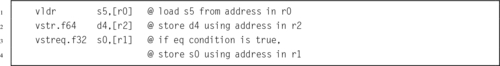
9.4.1 Load/Store Single Register
The following instructions are used to load or store a single VFP register:
vstr Store VFP Register.
Syntax
• <op> may be either ld or st.
• Fd may be any single or double precision register.
• Rn may be any ARM integer register.
• <cond> is an optional condition code.
• <prec> may be either f32 or f64.
Operations


Examples
9.4.2 Load/Store Multiple Registers
These instructions load or store multiple floating-point registers:
vldm Load Multiple VFP Registers, and
vstm Store Multiple VFP Registers.
As with the integer ldm and stm instructions, there are multiple versions for use in moving data and accessing stacks.
Syntax
• <op> may be either ld or st.
ia Increment address after each transfer.
db Decrement address before each transfer.
• Rn may be any ARM integer register.
• <cond> is an optional condition code.
• <prec> may be either f32 or f64.
• <list> may be any set of contiguous single precision registers, or any set of contiguous double precision registers.
• If mode is db then the ! is required.
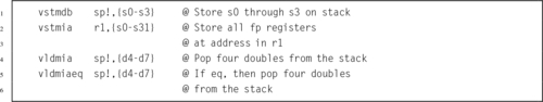
• vpop <list> is equivalent to vldmia sp!,< list >.
• vpush <list> is equivalent to vstmdb sp!,< list >.
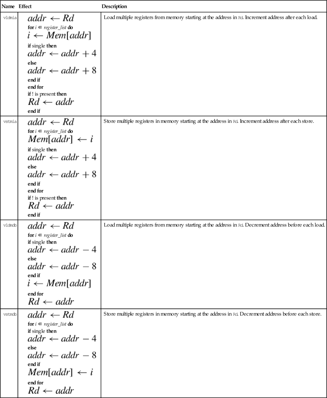
Operations
| Name | Effect | Description |
| vldmia |
for i ∈ register_list do
if single then
else
end if end for if ! is present then
end if | Load multiple registers from memory starting at the address in Rd. Increment address after each load. |
| vstmia |
for i ∈ register_list do
if single then
else
end if end for if ! is present then
end if | Store multiple registers in memory starting at the address in Rd. Increment address after each store. |
| vldmdb |
for i ∈ register_list do if single then
else
end if
end for
| Load multiple registers from memory starting at the address in Rd. Decrement address before each load. |
| vstmdb |
for i ∈ register_list do if single then
else
end if
end for
| Store multiple registers in memory starting at the address in Rd. Decrement address before each store. |


Examples
9.5 Data Processing Instructions
These operations are vector-capable. For details on how to use vector mode, refer to Section 9.2.2. Instructions are provided to perform the four basic arithmetic functions, plus absolute value, negation, and square root. There are also special forms of the multiply instructions that perform multiply-accumulate.
9.5.1 Copy, Absolute Value, Negate, and Square Root
The unary operations require on source operand and a destination register. The source and destination can be the same register. There are four unary operations:
vcpy Copy VFP Register (equivalent to move),
vabs Absolute Value,
vneg Negate, and
vsqrt Square Root.
Syntax
• <op> is one of cpy, abs, neg, or sqrt.
• <cond> is an optional condition code.
• <prec> may be either f32 or f64.
Operations


Examples

9.5.2 Add, Subtract, Multiply, and Divide
The basic mathematical operations require two source operands and one destination. There are five basic mathematical operations:
vsub Subtract,
vmul Multiply,
vnmul Negate and Multiply, and
vdiv Divide.
Syntax
• <op> is one of add, sub, mul, nmul, or div.
• <cond> is an optional condition code.
• <prec> may be either f32 or f64.
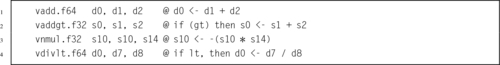
Operations


Examples
9.5.3 Compare
The compare instruction subtracts the value in Fm from the value in Fd and sets the flags in the FPSCR based on the result. The comparison operation will raise an exception if one of the operations is a signalling NaN. There is also a version of the instruction that will raise an exception if either operand is any type of NaN. The two comparison instructions are:
vcmpe Compare with Exception.
Syntax
• If e is present, an exception is raised if either operand is any kind of NaN. Otherwise, an exception is raised only if either operand is a signaling NaN.
• <cond> is an optional condition code.
• <prec> may be either f32 or f64.
Operations

Examples

9.6 Data Movement Instructions
With the addition of all of the VFP registers, there many more possibilities for how data can be moved. There are many more registers, and VFP registers may be 32 or 64 bit. This results in several possible combinations for moving data among all of the registers. The VFP instruction set includes instructions for moving data between two VFP registers, between VFP and integer registers, and between the various system registers.
9.6.1 Moving Between Two VFP Registers
The most basic move instruction involving VFP registers simply moves data between two floating point registers. The instruction is:
vmov Move Between VFP Registers.
Syntax
• Fd and Fm must be the same size.
• <cond> is an optional condition code.
• <prec> is either f32 or f64.
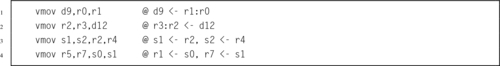
Operations

Examples

9.6.2 Moving Between VFP Register and One Integer Register
This version of the move instruction allows 32 bits of data to be moved between an ARM integer register and a floating point register. The instruction is:
vmov Move Between VFP and One ARM Integer Register.
Syntax
• Rd is an ARM integer register.
• Sd is a VFP single precision register.
• <cond> is an optional condition code.
Operations


Examples

9.6.3 Moving Between VFP Register and Two Integer Registers
This version of the move instruction is used to transfer 64 bits of data between ARM integer registers and floating point registers:
vmov Move Between VFP and Two ARM Integer Registers.
Syntax
• Source and destination must be VFP or integer registers. One of them must be a set of ARM integer registers, and the other must be VFP coprocessor registers. The following table shows the possible choices for sources and destinations.
• Sd and Sd’ must be adjacent, and Sd’ must be the higher-numbered register.
• <cond> is an optional condition code.
Operations


Examples
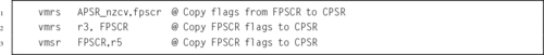
9.6.4 Move Between ARM Register and VFP System Register
There are two instructions which allow the programmer to examine and change bits in the VFP system register(s):
vmrs Move From VFP System Register to ARM Register, and
vmsr Move From ARM Register to VFP System Register.
User programs should only access the FPSCR to check the flags and control vector mode.
Syntax
• VFPsysreg can be any of the VFP system registers.
• Rd can be APSR_nzcv or any ARM integer register.,
• <cond> is an optional condition code.
Operations


Examples
9.7 Data Conversion Instructions
The ARM VFP provides several instructions for converting between various floating point and integer formats. Some VFP versions also have instructions for converting between fixed point and floating point formats.
9.7.1 Convert Between Floating Point and Integer
These instructions are used to convert integers to single or double precision floating point, or for converting single or double precision to integer:
vcvt Convert Between Floating Point and Integer
vcvtr Convert Floating Point to Integer with Rounding
These instructions always use a single precision register for the integer, but the floating point argument can be single precision or double precision. Some versions of the VFP do not support the double precision versions.
Syntax
• The optional r makes the operation use the rounding mode specified in the FPSCR. The default is to round toward zero.
• <cond> is an optional condition code.
• The <type> can be either u32 or s32 to specify unsigned or signed integer.
• These instructions can also convert from fixed point to floating point if followed by an appropriate vmul.
Operation
| Opcode | Effect | Description |
| vcvt.f64.s32 |  | Convert signed integer to double |
| vcvt.f32,s32 |  | Convert signed integer to single |
| vcvt.f64.u32 | | Convert unsigned integer to double |
| vcvt.f32.u32 | | Convert unsigned integer to single |
| vcvt.s32.f32 |  | Convert single to signed integer |
| vcvt.u32.f32 |  | Convert single to unsigned integer |
| vcvt.s32.f64 |  | Convert double to signed integer |
| vcvt.u32.f64 |  | Convert double to unsigned integer |
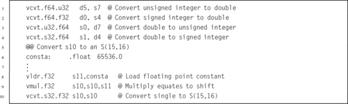
Examples
9.7.2 Convert Between Fixed Point and Single Precision
VFPv3 and higher coprocessors have additional instructions used for converting between fixed point and single precision floating point:
vcvt Convert To or From Fixed Point.
Syntax
• <cond> is an optional condition code.
• <td> specifies the type and size of the fixed point number, and must be one of the following:
u32 unsigned 32 bit value,
s16 signed 16 bit value, or
u16 unsigned 16 bit value.
• The #fbits operand specifies the number of fraction bits in the fixed point number, and must be less than or equal to the size of the fixed point number indicated by <td>.
Operations
| Name | Effect | Description |
| vcvt.s32.f32 |  | Convert single precision to 32-bit signed fixed point. |
| vcvt.u32.f32 |  | Convert single precision to 32-bit unsigned fixed point. |
| vcvt.s16.f32 |  | Convert single precision to 16-bit signed fixed point. |
| vcvt.u16.f32 |  | Convert single precision to 16-bit unsigned fixed point. |
| vcvt.f32.s32 |  | Convert signed 32-bit fixed point to single precision |
| vcvt.f32.u32 | | Convert unsigned 32-bit fixed point to single precision |
Examples

9.8 Floating Point Sine Function
A fixed point implementation of the sine function was discussed in Section 8.7, and shown to be superior to the floating point sine function provided by GCC. Now that we have covered the VFP instructions, we can write an assembly version using floating point which also performs better than the routines provided by GCC.
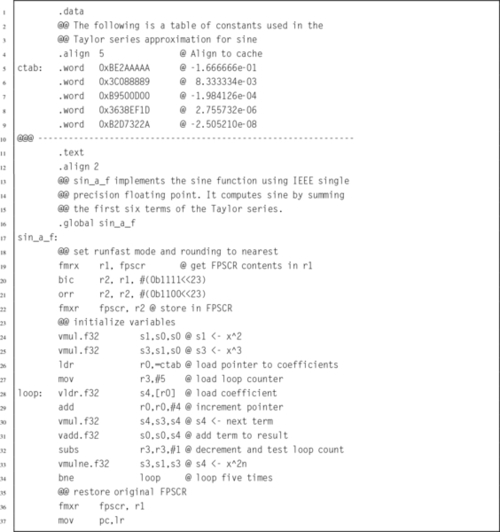
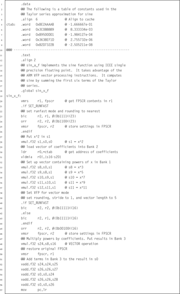
9.8.1 Sine Function Using Scalar Mode
Listing 9.1 shows a single precision floating point implementation of the sine function, using the ARM VFPv3 instruction set. It works in a similar way to the previous fixed point code. There is a table of constants, each of which is the reciprocal of one of the factorial divisors in the Taylor series for sine. The subroutine calculates the powers of x one-by-one, and multiplies each power by the next constant in the table, summing the results as it goes. Note that the table of constants is shorter than the fixed point version of the code, because there are fewer bits of precision in a single precision floating point number than there are in the fixed point representation that was used previously.
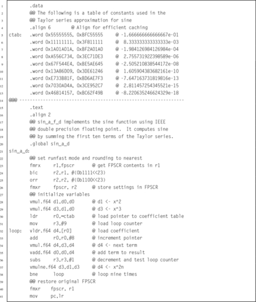
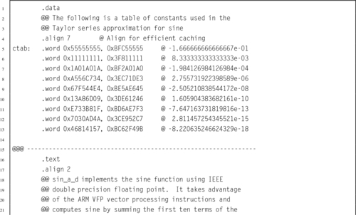
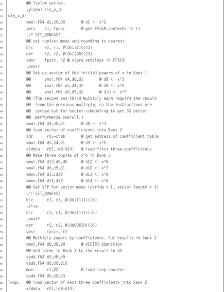
Listing 9.2 shows a double precision floating point implementation of the sine function, using the ARM VFPv3 instruction set. Again, there is a table of constants, each of which is the reciprocal of one of the factorial divisors in the Taylor series for sine. The subroutine calculates the powers of x one-by-one, and multiplies each power by the next constant in the table, summing the results as it goes. Note that the table of constants is longer than the fixed point version of the code, because there are more bits of precision in a double precision floating point number than there are in the fixed point representation that was used previously.
9.8.2 Sine Function Using Vector Mode
The previous implementations are already faster than the implementations provided by GCC, However, it may be possible to gain a little more performance by using VFP vector mode. In the single precision code, there are five terms to be added. Since single precision vectors can have up to eight elements, the code should not require any loop at all.
Listing 9.3 shows a single precision floating point implementation of the sine function, using the ARM VFPv3 instruction set in vector mode. It performs the same operations as the previous implementation, but instead of using a loop, all of the data is pre-loaded into vector banks and then a vector multiply operation is performed. The processor is then returned to scalar mode, and the summation is performed. This implementation is slightly faster than the previous version.
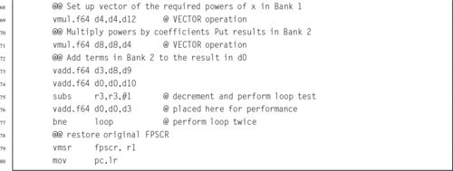
Listing 9.4 shows a double precision floating point implementation of the sine function, using the ARM VFPv3 instruction set in vector mode. It performs the same operations as the previous implementation, but performs the nine multiplications in three groups of three, using vector operations. Also, computing the powers of x is done within the loop, using a vector multiply. In this case, the vector code is significantly faster than the scalar version.
9.8.3 Performance Comparison
Table 9.2 shows the performance of various implementations of the sine function, with and without compiler optimization. The Single Precision C and Double Precision C implementations are the standard implementations provided by GCC.
Table 9.2
Performance of sine function with various implementations
| Optimization | Implementation | CPU seconds |
| None | Single Precision Scalar Assembly | 2.96 |
| Single Precision Vector Assembly | 2.63 | |
| Single Precision C | 8.75 | |
| Double Precision Scalar Assembly | 4.59 | |
| Double Precision Vector Assembly | 3.75 | |
| Double Precision C | 9.21 | |
| Full | Single Precision Scalar Assembly | 2.16 |
| Single Precision Vector Assembly | 2.06 | |
| Single Precision C | 2.59 | |
| Double Precision Scalar Assembly | 3.88 | |
| Double Precision Vector Assembly | 3.16 | |
| Double Precision C | 8.49 |
When compiler optimization is not used, the single precision scalar VFP implementation achieves a speedup of about 2.96, and the vector implementation achieves a speedup of about 3.33 compared to the GCC implementation. The double precision scalar VFP implementation achieves a speedup of about 2.01, and the vector implementation achieves a speedup of about 2.46 compared to the GCC implementation.
When the best possible compiler optimization is used (-Ofast), the single precision scalar VFP implementation achieves a speedup of about 1.20, and the vector implementation achieves a speedup of about 1.26 compared to the GCC implementation. The double precision scalar VFP implementation achieves a speedup of about 2.19, and the vector implementation achieves a speedup of about 2.69 compared to the GCC implementation.
In most cases, the assembly versions were significantly faster than the functions provided by GCC. GCC with full optimization using single-precision numbers was competitive, but the assembly language vector implementation still beat it by over 25%. It is clear that writing some functions in assembly can result in large performance gains.
9.9 Alphabetized List of VFP Instructions
| Name | Page | Operation |
| vabs | 277 | Absolute Value |
| vadd | 278 | Add |
| vcmp | 279 | Compare |
| vcmpe | 279 | Compare with Exception |
| vcpy | 277 | Copy VFP Register |
| vcvt | 283 | Convert Between Floating Point and Integer |
| vcvt | 284 | Convert To or From Fixed Point |
| vcvtr | 283 | Convert Floating Point to Integer with Rounding |
| vdiv | 278 | Divide |
| vldm | 275 | Load Multiple VFP Registers |
| vldr | 274 | Load VFP Register |
| vmov | 280 | Move Between VFP and One ARM Integer Register |
| vmov | 281 | Move Between VFP and Two ARM Integer Registers |
| vmov | 279 | Move Between VFP Registers |
| vmrs | 282 | Move From VFP System Register to ARM Register |
| vmsr | 282 | Move From ARM Register to VFP System Register |
| vmul | 278 | Multiply |
| vneg | 277 | Negate |
| vnmul | 278 | Negate and Multiply |
| vsqrt | 277 | Square Root |
| vstm | 275 | Store Multiple VFP Registers |
| vstr | 274 | Store VFP Register |
| vsub | 278 | Subtract |
9.10 Chapter Summary
The ARM VFP coprocessor adds a great deal of power to the ARM architecture. The register set is expanded to hold up to four times the amount of data that can be held in the ARM integer registers. The additional instructions allow the programmer to deal directly with the most common IEEE 754 formats for floating point numbers. The ability to treat groups of registers as vectors adds a significant performance improvement. Access to the vector features is only possible through assembly language. The GCC compiler is not capable of using these advanced features, which gives the assembly programmer a big advantage when high-performance code is needed.
Exercises
9.1 How many registers does the VFP coprocessor add to the ARM architecture?
9.2 What is the purpose of the FZ, DN, and IDE, IXE, UFE, OFE, DZE, and IOE bits in the FPSCR? What is it called when FZ and DN are set to one and all of the others are set to zero?
9.3 If a VFP coprocessor is present, how are floating point parameters passed to subroutines? How is a pointer to a floating point value (or array of values) passed to a subroutine?
9.4 Write the following C code in ARM assembly:
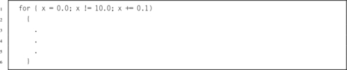
9.5 In the previous exercise, the C code contains a subtle bug.
b. Show two ways to fix the code in ARM assembly. Hint: One way is to change the amount of the increment, which will change the number of times that the loop executes.
9.6 The fixed point sine function from the previous chapter was not compared directly to the hand-coded VFP implementation. Based on the information in Tables 9.2 and 8.4, would you expect the fixed point sine function from the previous chapter to beat the hand-coded assembly VFP sine function in this chapter? Why or why not?
9.7 3-D objects are often stored as an array of points, where each point is a vector (array) consisting of four values, x, y, z, and the constant 1.0. Rotation, translation, scaling and other operations are accomplished by multiplying each point by a 4 × 4 transformation matrix. The following C code shows the data types and the transform operation:
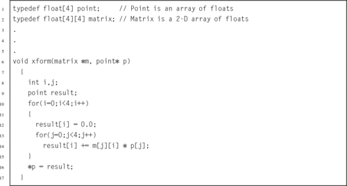
Write the equivalent ARM assembly code.
9.8 Optimize the ARM assembly code you wrote in the previous exercise. Use vector mode if possible.
9.9 Since the fourth element of the point is always 1.0, there is no need to actually store it. This will reduce memory requirements by about 25%, and require one fewer multiply. The C code would look something like this:
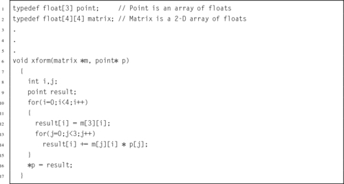
Write optimal ARM VFP code to implement this function.
9.10 The function in the previous problem would typically be called multiple times to process an array of points, as in the following function:
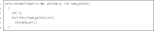
This could be somewhat inefficient. Re-write this function in assembly so that the transformation of each point is done without resorting to a function call. Make your code as efficient as possible.