Table of Contents for
Raspberry Pi Cookbook, 2nd Edition
 Raspberry Pi Cookbook, 2nd Edition
Published by
O'Reilly Media, Inc., 2016
Raspberry Pi Cookbook, 2nd Edition
Published by
O'Reilly Media, Inc., 2016
- nav
- Cover
- Raspberry Pi Cookbook
- Raspberry Pi Cookbook
- Preface to the Second Edition
- Setup and Management
- Networking
- Operating System
- Software
- Python Basics
- Python Lists and Dictionaries
- Advanced Python
- Computer Vision
- Hardware Basics
- Controlling Hardware
- Motors
- Digital Inputs
- Sensors
- Displays
- The Internet of Things
- Arduino and Raspberry Pi
- Parts and Suppliers
- Raspberry Pi Pinouts
- Index
- About the Author
- Colophon
Chapter 16. Arduino and Raspberry Pi
16.0 Introduction
While a Raspberry Pi is ideal for projects that need a network connection or a graphical user interface, the low-power GPIO outputs and lack of any analog inputs puts it at a disadvantage to microcontroller boards, such as the Arduino (Figure 16-1). Fortunately, it is possible to have the best of both worlds by connecting an Arduino to a Raspberry Pi and allowing the Arduino to interface with external electronics.
Arduino boards are superficially a little like a Raspberry Pi in that they are small and essentially a computer. However, Arduino boards are very different from the Raspberry Pi in a number of respects:
-
They do not have any interface to keyboard, mouse, or screen.
-
They have just 2 KB of RAM and 32 KB of flash for storing programs.
-
Their processor runs at just 16 MHz compared with the Raspberry Pi’s 700 MHz.
This might lead you to wonder why you would use such an apparently feeble board rather than the Raspberry Pi directly.
The answer is that Arduino boards, the most common being the Arduino Uno, are better than the Raspberry Pi at interfacing with external electronics in several ways. For example, Arduino boards have:
-
14 digital inputs/outputs, like the Raspberry Pi’s GPIO pins, but each pin can provide up to 40 mA compared with the original Raspberry Pi’s 3 mA. This enables them to power more devices without the need for extra electronics.
-
6 analog inputs. This makes connecting analog sensors much easier (see Recipe 16.7).
-
6 PWM outputs. These outputs are hardware-timed and produce a much more accurate PWM signal than can be achieved with the Raspberry Pi, making them a lot better for controlling servo motors.
-
A huge range of plug-in shields for everything from motor control to LCD displays of various sorts.
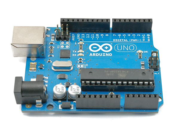
Figure 16-1. An Arduino Uno board
In many ways, using a Raspberry Pi with an Arduino to handle all the low-level stuff is a good combination, playing to the strengths of both boards. This is taken to its extreme with interface boards that have a GPIO connector and also include Arduino-compatible hardware such as the aLaMode (Recipe 16.13).
16.1 Programming an Arduino from Raspberry Pi
Note
Be sure to check out the accompanying video for this recipe at http://razzpisampler.oreilly.com.
Solution
The Arduino IDE is available for the Raspberry Pi. It is a little bit slow, but usable. You will definitely want to use the superior speed of the Raspberry Pi 2 when using the Arduino IDE. Use these commands to install the Arduino IDE:
$ sudo apt-get update
$ sudo apt-get install arduino
After installation, you will find an Electronics group in your Programs menu (Figure 16-2).
To program the Arduino IDE, connect it to the Raspberry Pi through its USB cable. The easiest way to set up your Pi to use the Arduino IDE is to run a script created by Kevin Osborn that configures the serial ports and Arduino profiles necessary to get things running. This has the advantage that it also sets up the aLaMode board to be ready for use (Recipe 16.13).
To download and run this script, follow these steps:
$ https://github.com/wyolum/alamode/raw/master/bundles/alamode-setup.tar.gz
$ tar -xvzf alamode-setup.tar.gz
$ cd alamode-setup
$ sudo ./setup
You can now connect your Arduino to your Raspberry Pi. From the Tools menu, select Board and set the board type to Arduino Uno. Then, from the Serial Port option, select /dev/ttyACM0. To upload a test program that will make the LED on the Arduino blink, select the File menu and then click “Examples, Basic,” and finally click Blink. Click on the right arrow on the toolbar to begin the compile and upload process. If all is well, you should see a “Done Uploading” message in the status area at the bottom of the IDE window.
Tip
If you find that the device ttyACM0 is not listed even though your Arduino is plugged in, try restarting the Arduino IDE. If that doesn’t work, then you may have to reboot your Raspberry Pi. Leave the Arduino connected while you reboot and restart the Arduino IDE.
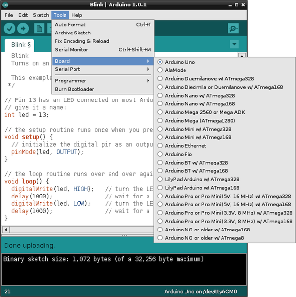
Figure 16-2. The Arduino IDE running on Raspberry Pi
Discussion
To get the most out of using Arduino with Raspberry Pi, you need to learn a little Arduino programming. You may find the book Programming Arduino: Getting Started with Sketches (McGraw-Hill/Tab Books), by yours truly, helpful.
You can, however, make use of an Arduino without needing to write any code on the Arduino side, using a project called PyFirmata. Recipe 16.3 explains how to use PyFirmata.
See Also
The Arduino IDE setup script came from the blog Bald Wisdom.
16.2 Communicating with the Arduino by Using the Serial Monitor
Solution
The Arduino IDE includes a feature called the serial monitor, which allows you to both send text messages to the Arduino and see messages from the Arduino over the USB cable.
To try this out, you first need to write a very short Arduino program (programs are called sketches in the Arduino world). This sketch will just repeat a message, sending it every second.
The Arduino sketch is listed here. As with all the program examples in this book, you can also download the program from http://www.raspberrypicookbook.com, where it is contained in the folder ArduinoHello. Just follow the link to this book and then click Code.
Use File→New to create a new sketch, and paste the following text into it before uploading it to the Arduino.
voidsetup(){Serial.begin(9600);}voidloop(){Serial.println("Hello Raspberry Pi");delay(1000);}
As soon as the sketch is uploaded onto the Arduino, it will start sending the message “Hello Raspberry Pi” over serial. You won’t see this until you open the serial monitor (Figure 16-3) by clicking the icon that looks like a magnifying glass on the right of the toolbar.
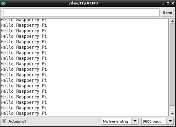
Figure 16-3. Viewing messages with the serial monitor
The serial monitor has a drop-down list in the bottom-right corner, where you can select the baud rate (speed of communication). If this isn’t already set to 9600, change it to that value.
Discussion
In some of the later recipes in this chapter (Recipes 16.10 and 16.11), you look at writing your own custom code to communicate with Python programs running on the Raspberry Pi so that you don’t need to have the Arduino IDE running.
A more generic approach is to use something called PyFirmata, which avoids the need for any programming on the Raspberry Pi. See Recipe 16.3 for details.
See Also
Arduino is quite easy to learn; here are some links to books and online resources to get you started:
-
Programming Arduino: Getting Started with Sketches (Tab Books) by Simon Monk
-
Arduino Cookbook (O’Reilly) by Michael Margolis
16.3 Setting Up PyFirmata to Control an Arduino from a Raspberry Pi
Solution
Connect the Arduino to a USB socket of the Raspberry Pi so that the computer can communicate and send power to the Arduino.
Next, install the Firmata sketch onto the Arduino and the PyFirmata onto your Raspberry Pi. This entails installing the Arduino IDE, so if you haven’t already done so, follow Recipe 16.1.
The Arduino IDE includes Firmata, so all you have to do to install Firmata onto your Arduino board is to upload a sketch. You will find the sketch at File→Examples→Firmata→StandardFirmata.
Once Firmata is installed, the Arduino waits for communication from the Raspberry Pi.
Now you need to install PyFirmata, the other half of the link. This requires the use of the PySerial library, so follow Recipe 9.6 to install this.
You can now download and install PyFirmata by using these commands:
$ git clone https://github.com/tino/pyFirmata.git
$ cd pyFirmata
$ sudo python setup.py install
You can try out the PyFirmata library from the Python console. Enter the following commands to turn on the built-in LED on Arduino pin 13 (marked with an L) and then turn it off again.
$ sudo python
Python 2.7.3 (default, Jan 13 2013, 11:20:46)
[GCC 4.6.3] on linux2
Type "help", "copyright", "credits" or "license" for more information.
>>>importpyfirmata>>>board=pyfirmata.Arduino('/dev/ttyACM0')>>>pin13=board.get_pin('d:13:o')>>>pin13.write(1)>>>pin13.write(0)>>>board.exit()
Discussion
The preceding code first imports the PyFirmata library and then makes an instance of Arduino called board, using the USB interface (/dev/ttyACM0) as its parameter. You can then gain a reference to one of the Arduino pins (in this case, 13) and set it to be a digital output. The d is for digital, 13 is the pin number, and o is for output.
To set the output pin high, use write(1), and to set it low, use write(0). You can also use True and False in place of 1 and 0.
Figure 16-4 shows an Arduino with the rows of connections down both sides of the board.
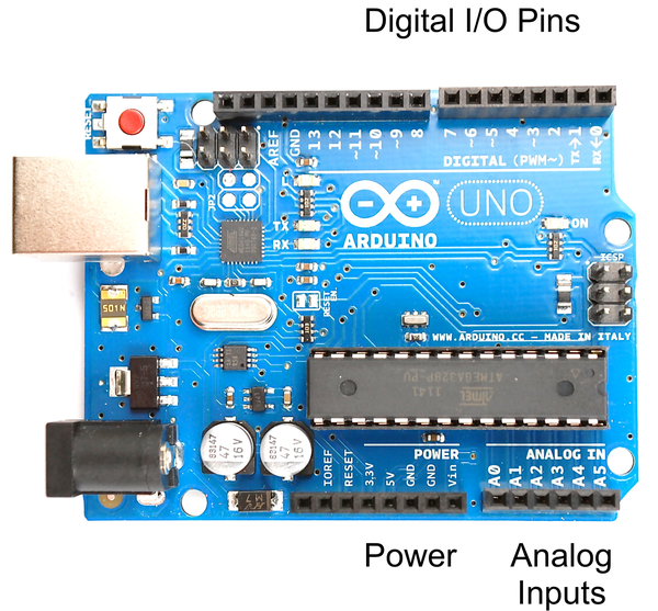
Figure 16-4. I/O pins on an Arduino Uno
The pins at the top marked 0 to 13 can be used as digital inputs or outputs. Some of these pins are also used for other things. Pins 0 and 1 are used as a serial interface, and are in use when the USB port is being used; and pin 13 is attached to the on-board LED marked with an L. The digital I/O pins 3, 5, 6, 9, 10, and 11 have a ~ symbol next to them that indicates that they can be used for PWM output (see Recipe 10.3).
On the other side of the board, there is one set of connectors that supplies power at 5V and 3.3V, and six analog inputs marked A0 to A5.
An Arduino Uno on its own uses about 50 mA, which, given that the Raspberry Pi itself is probably using about 10 times that, makes it perfectly possible to power the Arduino from the USB connection of the Raspberry Pi. However, if you start attaching a lot of external electronics to the Arduino, and the current consumption increases, then you may want to power the Arduino from its own power adapter by using the DC barrel socket. This will accept 7V to 12V DC.
The only real downside of using Firmata is that because all instructions have to come from the Raspberry Pi, it doesn’t make much use of Arduino’s ability to run independently. For advanced projects, you will probably end up writing your own Arduino code that receives instructions from the Raspberry Pi and/or sends messages to the Raspberry Pi while it gets on with other tasks.
16.4 Writing Digital Outputs on an Arduino from a Raspberry Pi
Solution
In Recipe 16.3, you flashed the built-in LED (labeled with an L) on the Arduino board. Here, you build on this to attach an external LED and write a short Python program to make it blink.
To make this recipe, you need:
-
Arduino Uno (see “Modules”)
-
Breadboard and jumper wires (see “Prototyping Equipment”)
-
270Ω resistor (see “Resistors and Capacitors”)
-
LED (see “Opto-Electronics”)
As an alternative to using a breadboard and an LED, you could plug in one color channel of a Squid RGB LED (Recipe 9.10).
Connect the breadboard, fastening the components to the Arduino as shown in Figure 16-5.
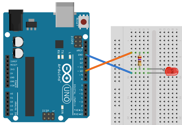
Figure 16-5. Wiring diagram for Arduino and LED
If you haven’t already done so, follow Recipe 16.3 to set up PyFirmata.
The following Python script makes the LED blink at a rate of about 1 Hz. Open an editor (nano or IDLE) and paste in the following code. As with all the program examples in this book, you can also download the program from the Code section of http://www.raspberrypicookbook.com, where it is called ardu_flash.py.
importpyfirmataimporttimeboard=pyfirmata.Arduino('/dev/ttyACM0')led_pin=board.get_pin('d:10:o')whileTrue:led_pin.write(1)time.sleep(0.5)led_pin.write(0)time.sleep(0.5)
Discussion
This is very similar to connecting an LED to a Raspberry Pi (Recipe 10.1). However, note that since Arduino outputs can supply a lot more current than Raspberry Pi outputs, you can use a smaller value resistor and make the LED a bit brighter. Arduino outputs are also 5V rather than 3.3V.
If you want the user interface to control the LED like you had in Recipe 10.8 (and shown in Figure 16-6), it’s pretty straightforward to modify the code. You can find the modified program, called ardu_gui_switch.py, on the book’s website. Remember, this will not work from the SSH command line. You need to have access to the Raspberry Pi’s graphical environment so that you can see the user interface.
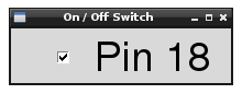
Figure 16-6. A user interface for turning things on and off
See Also
See Recipe 10.1 for controlling an LED directly from a Raspberry Pi.
16.5 Using PyFirmata with TTL Serial
Solution
Use a level converter to connect the RXD pin of the Raspberry Pi to the Tx pin of the Arduino, and the TXD pin of the Raspberry Pi to the Rx pin of the Arduino.
To make this recipe, you need:
-
Arduino Uno (see “Modules”)
-
Breadboard and jumper wires (see “Prototyping Equipment”)
-
270Ω and 470Ω resistors (see “Resistors and Capacitors”) or a four-way bidirectional level converter (see “Modules”)
If you are using the level converter module, connect the breadboard as shown in Figure 16-7.
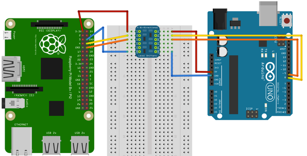
Figure 16-7. Wiring diagram, using a level converter module for serial communication with an Arduino
If, on the other hand, you are using the pair of resistors, then connect the breadboard as shown in Figure 16-8.
The Arduino Rx input is fine with just 3.3V from the Raspberry Pi TXD pin; however, the 5V coming from the Arduino Tx pin must be dropped to the 3V expected by the Raspberry Pi.
You will need to set up PyFirmata—see Recipe 16.3. The Arduino side of the project remains exactly the same as Recipe 16.4, where USB is used instead of the serial connection. There is one change that you need to make to the Python program running on the Raspberry Pi—change the device name from /dev/ttyACM0 to /dev/ttyAMA0, as the serial port has a different device name from the USB interface.
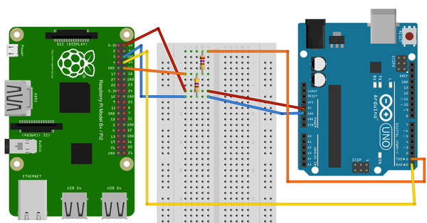
Figure 16-8. Wiring diagram, using a pair of resistors for serial communication with an Arduino
The following Python script makes the LED blink at a rate of about 1 Hz. Open an editor (nano or IDLE) and paste in the following code. As with all the program examples in this book, you can also download the program from the Code section of http://www.raspberrypicookbook.com, where it is called ardu_flash_ser.py.
importpyfirmataimporttimeboard=pyfirmata.Arduino('/dev/ttyAMA0')led_pin=board.get_pin('d:13:o')whileTrue:led_pin.write(1)time.sleep(0.5)led_pin.write(0)time.sleep(0.5)
Discussion
The level conversion is necessary because the Raspberry Pi serial port connections, RXD and TXD, operate at 3.3V, whereas the Arduino Uno operates at 5V. While it is OK for the 5V Arduino to use a 3.3V signal, the reverse is not true and a 5V signal connected to the 3.3V RXD pin is likely to damage the Raspberry Pi.
16.6 Reading Arduino Digital Inputs Using PyFirmata
Solution
Use PyFirmata to read a digital input on the Arduino.
To make this recipe, you need:
-
Arduino Uno (see “Modules”)
-
Breadboard and jumper wires (see “Prototyping Equipment”)
-
1kΩ resistor (see “Resistors and Capacitors”)
-
Tactile push switch (see “Miscellaneous”)
Connect the breadboard, fastening the components to the Arduino as shown in Figure 16-9.
If you haven’t already done so, follow Recipe 16.3 to set up PyFirmata.
The following Python script prints out a message every time the switch is pressed. It’s very similar to the program in (switch.py). Open an editor (nano or IDLE) and paste in the following code. As with all the program examples in this book, you can also download the program from the Code section of http://www.raspberrypicookbook.com, where it is called ardu_switch.py. Just follow the link to this book and then click Code.
importpyfirmataimporttimeboard=pyfirmata.Arduino('/dev/ttyACM0')switch_pin=board.get_pin('d:4:i')it=pyfirmata.util.Iterator(board)it.start()switch_pin.enable_reporting()whileTrue:input_state=switch_pin.read()ifinput_state==False:('Button Pressed')time.sleep(0.2)
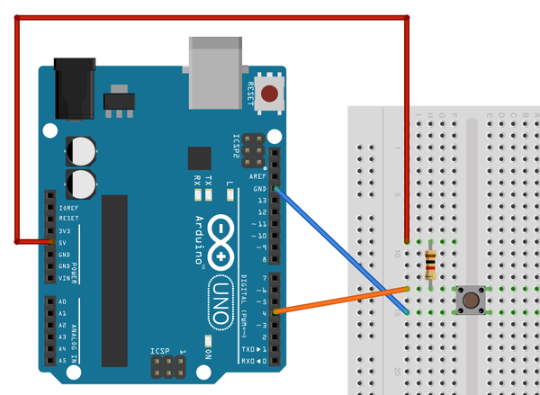
Figure 16-9. Wiring diagram for Arduino and push switch
When you run it, nothing will happen for a second or two, while the Firmata sketch starts and establishes communication with the Raspberry Pi. But, once it starts up, each time you press the button, a message will appear:
$ sudo python ardu_switch.py
Button Pressed
Button Pressed
Button Pressed
Discussion
PyFirmata uses the concept of an Iterator to monitor the Arduino input pin. The reasons for this are bound up in the implementation of Firmata. This means that you can’t simply read the value of an Arduino input pin on demand; instead, you have to create a separate Iterator thread that manages the reading of the switch by using the commands:
it=pyfirmata.util.Iterator(board)it.start()
You then also have to enable reporting for the pin you are interested in by using the command:
switch_pin.enable_reporting()
A side effect of this mechanism is that when you press Ctrl-C to exit the program, it won’t exit properly. There is no nice way to kill the Iterator thread other than to open another Terminal window or SSH session and kill the process (Recipe 3.26).
If the only Python process running is this program, you can kill it with the command:
$ sudo killall python
Simply disconnecting the Arduino from the Raspberry Pi, which will break the communication link, will also cause the Python program to exit.
See Also
This is very similar to connecting a switch directly to a Raspberry Pi (Recipe 12.1), and if you just have one switch, there is no real benefit in using an Arduino like this.
16.7 Reading Arduino Analog Inputs Using PyFirmata
Solution
Use PyFirmata to read an analog input on the Arduino.
To make this recipe, you need:
-
Arduino Uno (see “Modules”)
-
Breadboard and jumper wires (see “Prototyping Equipment”)
-
10kΩ trimpot (see “Resistors and Capacitors”)
Connect the breadboard, holding the components to the Arduino as shown in Figure 16-10.
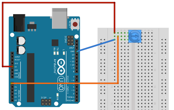
Figure 16-10. Wiring diagram for Arduino and trimpot
If you haven’t already done so, follow Recipe 16.3 to set up PyFirmata.
The following Python script (ardu_adc.py) will display both the raw reading from the analog input and the voltage at the analog input. It is very similar to the program in (adc_test.py).
Open an editor (nano or IDLE) and paste in the following code. As with all the program examples in this book, you can also download the program from the Code section of http://www.raspberrypicookbook.com, where it is called ardu_adc.py.
importpyfirmataimporttimeboard=pyfirmata.Arduino('/dev/ttyACM0')analog_pin=board.get_pin('a:0:i')it=pyfirmata.util.Iterator(board)it.start()analog_pin.enable_reporting()whileTrue:reading=analog_pin.read()ifreading!=None:voltage=reading*5.0("Reading=%f\tVoltage=%f"%(reading,voltage))time.sleep(1)
The analog reading will be a value between 0.0 and 1.0:
$ sudo python ardu_adc.py
Reading=0.000000    Voltage=0.000000
Reading=0.165200    Voltage=0.826000
Reading=0.784000    Voltage=3.920000
Reading=1.000000    Voltage=5.000000
Discussion
The program is very similar to that of Recipe 16.6. An Iterator must be used, and the same problems of stopping the program apply.
The if statement is needed, because if the first read is made before the actual reading from the analog input has happened, then the read will return None rather than a number. The if statement effectively causes the program to ignore any null readings.
See Also
To use digital inputs, see Recipe 16.6.
16.8 Analog Outputs (PWM) with PyFirmata
Solution
Use PyFirmata to send commands to an Arduino to generate a PWM signal on one of its outputs.
To make this recipe, you need:
-
Arduino Uno (see “Modules”)
-
Breadboard and jumper wires (see “Prototyping Equipment”)
-
270Ω resistor (see “Resistors and Capacitors”)
-
LED (see “Opto-Electronics”)
Connect the breadboard, holding the components to the Arduino as shown in Figure 16-11.
If you haven’t already done so, follow Recipe 16.3 to set up PyFirmata.

Figure 16-11. Wiring diagram for Arduino PWM control of an LED
The following Python script (ardu_pwm.py) will prompt you to enter a value for the PWM power and then set the LED brightness accordingly. Open an editor (nano or IDLE) and paste in the following code. As with all the program examples in this book, you can also download the program from the Code section of http://www.raspberrypicookbook.com, where it is called ardu_pwm.py.
importpyfirmataboard=pyfirmata.Arduino('/dev/ttyACM0')led_pin=board.get_pin('d:10:p')whileTrue:duty_s=raw_input("Enter Brightness (0 to 100):")duty=int(duty_s)led_pin.write(duty/100.0)
With the value entered as 100, the LED should be at full brightness. The brightness decreases as the number decreases:
$ sudo python ardu_pwm.py
Enter Brightness (0 to 100):100
Enter Brightness (0 to 100):50
Enter Brightness (0 to 100):10
Enter Brightness (0 to 100):5
Enter Brightness (0 to 100):
Discussion
The sketch for this is actually very straightforward. You define the output as PWM output using the command:
led_pin=board.get_pin('d:10:p')
The p is for PWM. But remember, this only works on Arduino pins marked with a ~ symbol.
We can also modify the slider control (Figure 16-12) so that it will operate through PyFirmata. You can download this sketch as ardu_gui_slider.
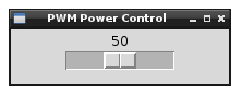
Figure 16-12. A user interface for controlling brightness
See Also
Although an Arduino can deliver 40 mA to an output—roughly 10 times the current available on a Raspberry Pi GPIO pin, it’s still not enough to directly drive a motor or high-power LED module. For these, you would need to use the circuit described in Recipe 11.4, modified to use an Arduino output pin rather than a Raspberry Pi GPIO pin.
16.9 Controlling a Servo Using PyFirmata
Solution
Use PyFirmata to send commands to an Arduino to generate the pulses necessary to control the position of a servo motor.
To make this recipe, you need:
-
Arduino Uno (see “Modules”)
-
Breadboard and jumper wires (see “Prototyping Equipment”)
-
1kΩ resistor (see “Resistors and Capacitors”)
-
LED (see “Integrated Circuits”)
Connect the breadboard as shown in Figure 16-13.
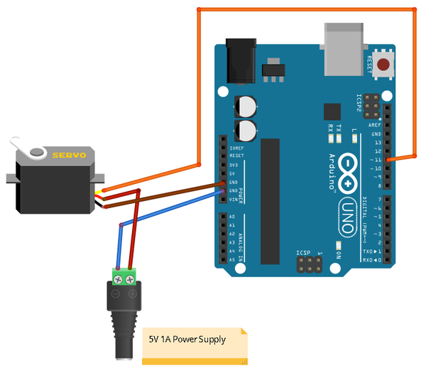
Figure 16-13. Wiring diagram for Arduino controlling a servo motor
If you have not already done so, follow Recipe 16.3 to set up PyFirmata.
The following Python script (ardu_servo.py) will prompt you to enter a value for the servo’s angle and then set the arm of the servo motor accordingly.
Open an editor (nano or IDLE) and paste in the following code. As with all the program examples in this book, you can also download the program from the Code section of http://www.raspberrypicookbook.com, where it is called ardu_servo.py.
importpyfirmataboard=pyfirmata.Arduino('/dev/ttyACM0')servo_pin=board.get_pin('d:11:s')whileTrue:angle_s=raw_input("Enter Angle (0 to 180):")angle=int(angle_s)servo_pin.write(angle)
With the value entered as 0, the servo should be at one end of its travel. Changing this to 180 sends it to the other end, and 90 puts it somewhere in the middle:
$ sudo python ardu_servo.py
Enter Angle (0 to 180):0
Enter Angle (0 to 180):180
Enter Angle (0 to 180):90
Discussion
The sketch for this is actually very straightforward. You define the output as a servo output by using the command:
led_pin=board.get_pin('d:11:s')
The s is for servo. This can be used on any of the Arduino digital pins.
If you’ve built Recipe 11.1, you will notice that, by comparison, there is no jitter of the servo when used with an Arduino in this way.
16.10 Custom Communication with an Arduino over TTL Serial
Solution
Use a level converter or pair of resistors to connect the RXD pin of the Raspberry Pi to the Tx pin of the Arduino, and the TXD pin of the Raspberry Pi to the Rx pin of the Arduino.
To make this recipe, you will need:
-
Arduino Uno (see “Modules”)
-
Breadboard and jumper wires (see “Prototyping Equipment”)
-
270Ω and 470Ω resistors (see “Resistors and Capacitors”) or a four-way bidirectional level converter (see “Modules”)
-
10kΩ trimpot (see “Resistors and Capacitors”)
If you are using the level converter module, then connect the breadboard as shown in Figure 16-14.
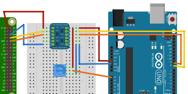
Figure 16-14. Wiring diagram for serial communication with an Arduino
If, on the other hand, you are using the pair of resistors, then connect the breadboard as shown in Figure 16-15.
The Arduino Rx input is fine with just 3.3V from the Raspberry Pi TXD pin; however, the 5V coming from the Arduino Tx pin must be dropped to the 3V expected by the Raspberry Pi.
You will need to disable serial port logging and install PySerial by following Recipe 9.6.
The following Python script (ardu_pi_serial.py) will prompt you to enter a command of either l or r. If you enter l, then the built-in Arduino LED will toggle on and off. If, on the other hand, you enter r, the Arduino will read the analog value from its analog input A0 and send back a number between 0 and 1023 as the reading.
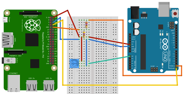
Figure 16-15. Wiring diagram for serial communication with an Arduino (using resistors)
Open an editor (nano or IDLE) and paste in the following code. As with all the program examples in this book, you can also download the program from the Code section of http://www.raspberrypicookbook.com, where it is called ardu_pi_serial.py.
importserialser=serial.Serial('/dev/ttyAMA0',9600)whileTrue:command=raw_input("Enter command: l - toggle LED, r - read A0 ")ifcommand=='l':ser.write('l')elifcommand=='r':ser.write('r')(ser.readline())
You also need to upload the following sketch, ArduinoSerial, onto your Arduino Uno. You can paste it into a new sketch window, and it is available with the rest of this book’s programs for download.
#include "SoftwareSerial.h"intledPin=13;intanalogPin=A0;SoftwareSerialser(8,9);// RX, TXbooleanledOn=false;voidsetup(){ser.begin(9600);pinMode(ledPin,OUTPUT);}voidloop(){if(ser.available()){charch=ser.read();if(ch=='l'){toggleLED();}if(ch=='r'){sendAnalogReading();}}}voidtoggleLED(){ledOn=!ledOn;digitalWrite(ledPin,ledOn);}voidsendAnalogReading(){intreading=analogRead(analogPin);ser.println(reading);}
Run the program and test that the built-in L LED on the Arduino toggles on and off using the l command. Then try setting the trimpot to different positions and take analog readings by sending the r command:
$ sudo python ardu_pi_serial.py
Enter command: l - toggle LED, r - read A0 l
Enter command: l - toggle LED, r - read A0 l
Enter command: l - toggle LED, r - read A0 r
0

Enter command: l - toggle LED, r - read A0 r
540

Enter command: l - toggle LED, r - read A0 r
1023
Discussion
The code in the Python program uses the PySerial library to open a connection onto the serial port. The main program loop then repeatedly asks for commands and processes them, in both cases by writing the single-character command to the serial port. In the case of the r command, it also reads a line from the serial connection and then prints it.
Note that, despite appearances, here the result of serial.readline is a string. If you need to convert this into a number, you can use the function int to convert it. For example:
line=ser.readline()value=int(line)
The Arduino sketch is a little more complicated. The example sketch provided can easily be modified to add more inputs or outputs and respond to more commands.
This sketch does not use the Arduino’s hardware serial port, as this is generally used by its USB connection. Instead, an Arduino library called SoftwareSerial is used to allow pins 8 and 9 to be used as Rx and Tx, respectively.
As with all Arduino sketches, there must be a setup function that is called one time when the Arduino starts up and a loop function is called repeatedly.
The setup function begins serial communication and sets the pin for the built-in LED (on Arduino pin 13) to be an output.
The loop function first checks to see if any serial messages have arrived by using the ser.available function call. If there is a message to process, it reads the character, and the following if clauses call the appropriate helper function to process the command.
See Also
For more information about the SoftwareSerial library, see http://arduino.cc/en/Reference/SoftwareSerial.
The alternative to writing your own custom code for communication is to use PyFirmata (Recipe 16.3).
In addition to communicating over serial, you can communicate with the Arduino using I2C (Recipe 16.11).
16.11 Custom Communication with an Arduino over I2C
Solution
The I2C bus has the concept of master and slave devices. The master device controls the bus and a number of slave devices can be connected to one master, with each slave having its own address.
You will install a sketch on the Arduino that makes it an I2C slave device and use the SMBus Python library to write an I2C program for the Raspberry Pi. The SDA, SCL, and ground connections of both devices need to be connected to each other, and the Arduino powered separately or from the 5V supply of the Raspberry Pi.
To make this recipe, you need:
-
Arduino Uno (see “Modules”)
-
Male-to-female jumper wires (see “Prototyping Equipment”)
Connect the breadboard, holding the components to the Arduino as shown in Figure 16-16.
The Arduino board used here is the latest Arduino Uno R3. If you have an older board that doesn’t have the two dedicated SCL and SDA pins, then you can connect the Raspberry Pi SDA and SCL pins to Arduino pins A4 and A5.
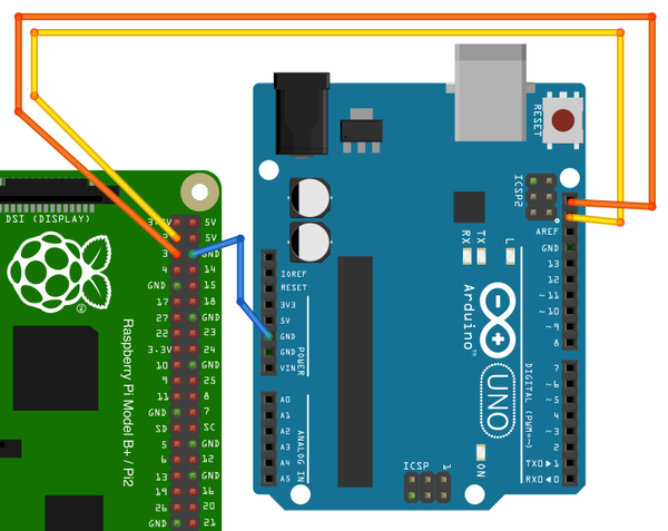
Figure 16-16. Wiring diagram for I2C communication with an Arduino
Install the following sketch onto the Arduino. You can find it, named ArduinoI2C, in the program downloads for this book at http://www.raspberrypicookbook.com.
#include <Wire.h>intSLAVE_ADDRESS=0x04;intledPin=13;intanalogPin=A0;booleanledOn=false;voidsetup(){pinMode(ledPin,OUTPUT);Wire.begin(SLAVE_ADDRESS);Wire.onReceive(processMessage);Wire.onRequest(sendAnalogReading);}voidloop(){}voidprocessMessage(intn){charch=Wire.read();if(ch=='l'){toggleLED();}}voidtoggleLED(){ledOn=!ledOn;digitalWrite(ledPin,ledOn);}voidsendAnalogReading(){intreading=analogRead(analogPin);Wire.write(reading>>2);}
You need to follow Recipe 9.3 to set up Raspberry Pi for I2C communication.
Open an editor (nano or IDLE) and paste in the following code. As with all the program examples in this book, you can also download the program from the Code section of http://www.raspberrypicookbook.com, where it is called ardu_pi_i2c.py.
importsmbusimporttime# for RPI revision 1, use "bus = smbus.SMBus(0)"bus=smbus.SMBus(1)# This must match what's in the Arduino SketchSLAVE_ADDRESS=0x04defrequest_reading():reading=int(bus.read_byte(SLAVE_ADDRESS))(reading)whileTrue:command=raw_input("Enter command: l - toggle LED, r - read A0 ")ifcommand=='l':bus.write_byte(SLAVE_ADDRESS,ord('l'))elifcommand=='r':request_reading()
The test program is very similar to the one used to demonstrate serial communication in Recipe 16.10. It’s designed to show communication in both directions. Entering the l command toggles the Arduino’s built-in LED on and off, and using the r command reports a reading from the Arduino’s A0 analog input. You can use a male-to-male jumper wire to connect A0 to 3.3V, 5V, or GND on the Arduino to get different readings:
$ sudo python ardu_pi_i2c.py
Enter command: l - toggle LED, r - read A0 l
Enter command: l - toggle LED, r - read A0 l
Enter command: l - toggle LED, r - read A0 r
184
Enter command: l - toggle LED, r - read A0
Discussion
The Arduino acts as the I2C slave in this arrangement and must therefore be given an address so that the master running on the Raspberry Pi can identify it if there is more than one slave device connected. In this case, the address is set to 0x04 and held in the SLAVE_ADDRESS variable.
The setup function in the Arduino then sets up two callback functions that will be used. The function processMessage will be invoked whenever the onReceive event occurs. This will happen whenever a command is sent from the Raspberry Pi. The other callback function, sendAnalogReading, is associated with the onRequest event. This occurs when the Raspberry Pi requests data, and will read the analog value, divide it by four to make it fit into a single byte, and then send it back to the Raspberry Pi.
The Python counterpart to this sketch first creates a new instance of SMBus called bus. This takes a single argument of 1. This is the I2C port on the Raspberry Pi to be used. This will be 1 unless you are using the very first version of the Raspberry Pi (revision 1). These boards have a black audio connector rather than the light blue connector of the revision 2 boards. If you have one of these older boards, use 0 as the argument here. The I2C port available at the GPIO connector was swapped between these two revisions.
The program prompts the user for a command (l or r). If the command is l, it writes the character l to the Arduino, which in turn causes the onReceive handler (processMessage) to be run. This in turn will call toggleLED.
If, on the other hand, the user enters the r command, then the request_reading function will be called. This will call read_byte in the SMBus library, which will cause the onRequest event in the Arduino sketch to be invoked.
You may be wondering why it is OK to connect the 5V Arduino directly to the I2C connections of the Raspberry Pi, without the level converter module that you had to use for serial communications (see Recipe 16.5). The reason is that the I2C bus standard operates at whatever voltage the pull-up resistors connected to SDA and SCL use. In this case, the Arduino Uno has no pull-up resistors connected to the I2C lines. These are provided by the Raspberry Pi, which pulls them up to 3.3V.
Warning
Although the Arduino has no pull-up resistors on the I2C lines, this is not true of all I2C devices. If the I2C device operates at 5V, make sure that it has no pull-up resistors (but if it does, you can usually remove them relatively easily).
See Also
For the serial equivalent to this setup, see Recipe 16.10.
16.12 Using Small Arduinos with a Raspberry Pi
Solution
Use one of the small breadboard-friendly Arduino boards.
Figure 16-17 shows an Arduino Pro Mini board. Boards like this have the great advantage that they can be plugged directly into the breadboard along with other components needed for the project. The Pro Mini board is also available in a 3.3V version, which avoids any need for level conversion when you’re using it with a Raspberry Pi.
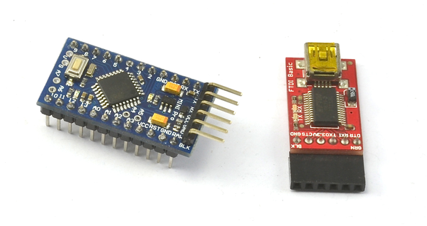
Figure 16-17. Arduino Pro Mini and programmer interface
Discussion
Some of these boards, such as the Pro Mini shown in Figure 16-17, require a USB programming interface. You can program them from the Raspberry Pi, or another computer if that proves problematic.
In addition to official Arduino boards, you can also find many low-cost clones that can make a great companion to the Raspberry Pi.
16.13 Getting Started with an aLaMode Board and a Raspberry Pi
Solution
The aLaMode board (see Table A-3) shown in Figure 16-18 is a wonderful board that is essentially an Arduino Uno with a Raspberry Pi GPIO socket in one corner. The aLaMode fits neatly onto the Raspberry Pi and allows you to use Arduino shields without the need for lots of extra wires. Although designed for the original Raspberry Pi, this board can also be used with the Raspberry Pi 2.
Note that the board in Figure 16-18 is shown without the header sockets needed to attach Arduino shields.
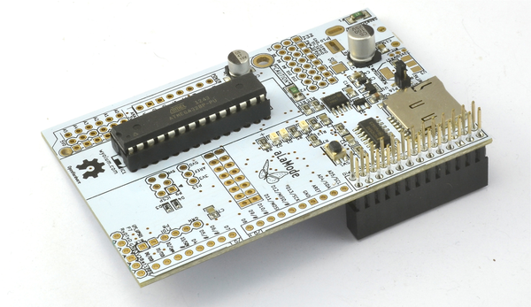
Figure 16-18. aLaMode interface board
The installation instructions in Recipe 16.1 will also set up aLaMode in your Arduino environment. From the Tools menu of the Arduino IDE, choose Board and then ALaMode (Figure 16-19).
You also need to set the serial port to /devttyS0 before programming the aLaMode, which takes place through the serial connection.
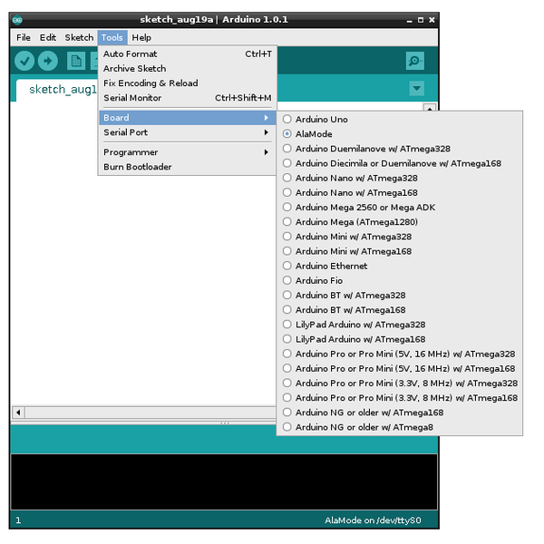
Figure 16-19. aLaMode board type on the Arduino IDE
Discussion
All the Firmata recipes in this chapter will work with the aLaMode, along with the custom serial communication example of Recipe 16.10. The only modification necessary is in the Python programs communicating with the aLaMode, as they must use the serial port rather than the USB port.
The aLaMode is hardwired to the Arduino’s Tx and Rx pins with built-in level conversion.
When using Firmata, you need to change the port from /dev/ttyACM0 to /dev/ttyAMA0:
board = pyfirmata.Arduino('/dev/ttyAMA0')
Similarly, if you are writing your own custom code, you will need to change the line that opens the serial connection so that it looks like this:
ser=serial.Serial('/dev/ttyAMA0',9600)
To try the aLaMode, just load the Standard Firmata sketch onto the aLaMode and then run the Python program ardu_flash_ser.py (Recipe 16.5).
Some of the interesting features of the aLaMode board are:
-
It can be powered from the 5V line of the Raspberry Pi GPIO connector or a separate 5V power adapter connected to its micro-USB socket.
-
The RTC is connected directly to the Raspberry Pi rather than the Arduino side of the board.
-
Arduino shields can be attached, with a high degree of compatibility (Recipe 16.14).
-
It can be an I2C slave. In addition to being linked by serial, the aLaMode’s I2C connections are also connected to those of the Raspberry Pi (Recipe 16.11).
-
It has a micro SD card reader.
-
It has headers for direct connection to servo motors (Recipe 16.9).
Warning
The aLaMode does suffer from one minor design flaw—with the Arduino shield headers soldered in place, the analog inputs A0 to A5 can easily touch the bare metal of the RJ45 Ethernet socket of the Raspberry Pi. To avoid this, place a couple of layers of electrical insulating tape over the top surface of the Ethernet socket on the Raspberry Pi before attaching the aLaMode (Figure 16-20).
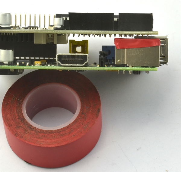
Figure 16-20. Insulating the RJ45 connector on a Raspberry Pi
See Also
The official aLaMode instructions can be found at http://bit.ly/1d2YMxh.
16.14 Using an Arduino Shield with an aLaMode Board and a Raspberry Pi
Solution
Use an aLaMode interface board. You may find that the board requires the Arduino-style header sockets for shields to be soldered into place.
As an example, you’ll connect an Arduino LCD shield to the aLaMode (Figure 16-21).
To make this recipe, you need:
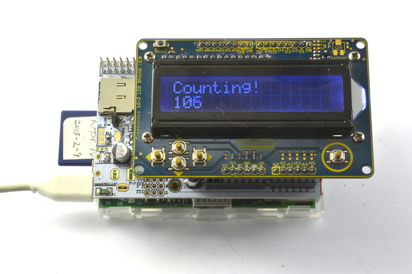
Figure 16-21. Using an LCD Arduino shield with an aLaMode
As with all the program examples in this book, you can also download this sketch from the Code section of http://www.raspberrypicookbook.com, where it is called AlaModeShield.
#include <LiquidCrystal.h>// pins for Freetronics LCD ShieldLiquidCrystallcd(8,9,4,5,6,7);voidsetup(){lcd.begin(16,2);lcd.("Counting!");}voidloop(){lcd.setCursor(0,1);lcd.(millis()/s1000);}
Simply upload the sketch onto the aLaMode and you should see the message “Counting” appear on the top row of the display, while the bottom row should show a number that counts the seconds.
Discussion
This example used the Freetronics LCD shield. There are a number of other LCD display shields, and some have different pin allocations. If you use a different module, you’ll need to change the line:
LiquidCrystal lcd(8, 9, 4, 5, 6, 7);
The parameters are the Arduino pins to be used for the following LCD connections: rs, enable, d4, d5, d6, and d7, in that order.
See Also
The reference material for the Arduino LiquidCrystal library can be found at http://arduino.cc/en/Reference/LiquidCrystal.