Table of Contents for
Raspberry Pi Cookbook, 2nd Edition
 Raspberry Pi Cookbook, 2nd Edition
Published by
O'Reilly Media, Inc., 2016
Raspberry Pi Cookbook, 2nd Edition
Published by
O'Reilly Media, Inc., 2016
- nav
- Cover
- Raspberry Pi Cookbook
- Raspberry Pi Cookbook
- Preface to the Second Edition
- Setup and Management
- Networking
- Operating System
- Software
- Python Basics
- Python Lists and Dictionaries
- Advanced Python
- Computer Vision
- Hardware Basics
- Controlling Hardware
- Motors
- Digital Inputs
- Sensors
- Displays
- The Internet of Things
- Arduino and Raspberry Pi
- Parts and Suppliers
- Raspberry Pi Pinouts
- Index
- About the Author
- Colophon
Chapter 10. Controlling Hardware
10.0 Introduction
In this chapter, you come to grips with the control of electronics through the Raspberry Pi’s GPIO connector.
Most of the recipes require the use of solderless breadboard and male-to-female and male-to-male jumper wires (see Recipe 9.8). To maintain compatibility with older 26-pin Raspberry Pi models, all the breadboard examples here only use the top 26 pins common to both GPIO layouts (see Recipe 9.1).
10.1 Connecting an LED
Note
Be sure to check out the accompanying video for this recipe at http://razzpisampler.oreilly.com.
Solution
Connect an LED to one of the GPIO pins using a 470Ω or 1kΩ series resistor to limit the current. To make this recipe, you will need:
-
Breadboard and jumper wires (see “Prototyping Equipment”)
-
470Ω resistor (see “Resistors and Capacitors”)
-
LED (see “Opto-Electronics”)
Figure 10-1 shows how you can wire this LED using a solderless breadboard and male-to-female jumper leads.
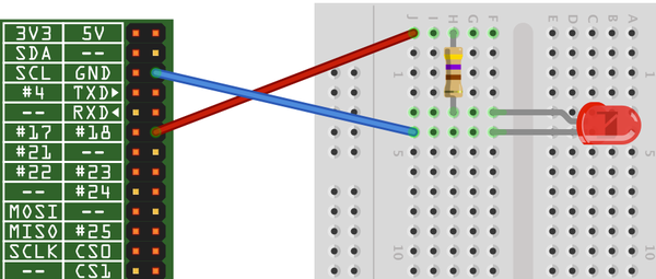
Figure 10-1. Connecting an LED to a Raspberry Pi
Having connected the LED, we need to be able to turn it on and off using commands from Python.
Start a Python console from the Terminal with superuser access and enter these commands:
$ sudo python
>>> import RPi.GPIO as GPIO
>>> GPIO.setmode(GPIO.BCM)
>>> GPIO.setup(18, GPIO.OUT)
>>> GPIO.output(18, True)
>>> GPIO.output(18, False)
This will turn your LED on and off.
Discussion
LEDs are a very useful, cheap, and efficient way of producing light, but you do have to be careful how you use them. If they are connected directly to a voltage source (such as a GPIO output) that is greater than about 1.7 volts, they will draw a very large current. This can often be enough to destroy the LED or whatever is providing the current—which is not good if your Raspberry Pi is providing the current.
You should always use a series resistor with an LED because the series resistor is placed between the LED and the voltage source, which limits the amount of current flowing through the LED to a level that is safe for both the LED and the GPIO pin driving it.
Raspberry Pi GPIO pins are only guaranteed to provide about 3mA or 16mA of current (depending on the board and number of pins in use)—see Recipe 9.2. LEDs will generally illuminate with any current greater than 1mA, but will be brighter with more current. Use Table 10-1 as a guide to selecting a series resistor based on the type of LED; the table also indicates the approximate current that will be drawn from the GPIO pin.
| LED type | Resistor | Current (mA) |
|---|---|---|
|
Red |
470Ω |
3.5 |
|
Red |
1kΩ |
1.5 |
|
Orange, yellow, green |
470Ω |
2 |
|
Orange, yellow, green |
1kΩ |
1 |
|
Blue, white |
100Ω |
3 |
|
Blue, white |
270Ω |
1 |
As you can see, in all cases, it is safe to use a 470Ω resistor. If you are using a blue or white LED, you can reduce the value of the series resistor considerably without risk of damaging your Raspberry Pi.
If you want to extend the experiments that you made in the Python console into a program that makes the LED blink on and off repeatedly, you could paste the following code into the IDLE (Recipe 5.2) or nano (Recipe 3.6) editors. Save the file as led_blink.py. You can also download the program from the Downloads section on the Raspberry Pi Cookbook website.
importRPi.GPIOasGPIOimporttimeGPIO.setmode(GPIO.BCM)GPIO.setup(18,GPIO.OUT)while(True):GPIO.output(18,True)time.sleep(0.5)GPIO.output(18,False)time.sleep(0.5)
Remember that to run the program, you must have superuser privileges for the RPi.GPIO library, so you need to use this command:
$ sudo python led_blink.py
See Also
Check out this handy series resistor calculator.
For more information on using breadboard and jumper wires with the Raspberry Pi, see Recipe 9.8.
10.2 Leaving the GPIO Pins in a Safe State
Solution
Use a try: finally: construction and the GPIO.cleanup method.
The blink example from Recipe 10.1 can be rewritten to exit safely as shown below. The file for the code is called led_blink_safe.py.
importRPi.GPIOasGPIOimporttimeGPIO.setmode(GPIO.BCM)GPIO.setup(18,GPIO.OUT)try:while(True):GPIO.output(18,True)time.sleep(0.5)GPIO.output(18,False)time.sleep(0.5)finally:("Cleaning Up!")GPIO.cleanup()
Now, when you Ctrl-C the program to close it, GPIO.cleanup will be called before the program exits.
Discussion
If cleanup is not called or the Pi is not rebooted, then pins set to be outputs will remain as outputs after the program has finished. If you were to start wiring up a new project, unaware of this problem, your new circuit might accidentally short a GPIO output to one of the supply rails or another GPIO pin in the opposite state.
A typical scenario where this might happen would be if you were to connect a push switch, connecting a GPIO pin that you had configured as an output and HIGH to GND, such as in Recipe 12.1.
In summary, either be careful when swapping hardware or use GPIO.cleanup as shown earlier, or reboot your Pi. In any case, its a good idea to power down your Pi while you are connecting new hardware to it.
See Also
For more information on exception handling in Python, see Recipe 7.10.
10.3 Controlling the Brightness of an LED
Solution
The RPi.GPIO library has a pulse-width modulation (PWM) feature that allows you to control the power to an LED and its brightness.
To try it out, connect an LED as described in Recipe 10.2 and run this test program (led_brightness.py):
importRPi.GPIOasGPIOled_pin=18GPIO.setmode(GPIO.BCM)GPIO.setup(led_pin,GPIO.OUT)pwm_led=GPIO.PWM(led_pin,500)pwm_led.start(100)whileTrue:duty_s=raw_input("Enter Brightness (0 to 100):")duty=int(duty_s)pwm_led.ChangeDutyCycle(duty)
If you are using Python 3 rather than Python 2, change the command raw_input to input.
Run the Python program, and you will be able to change the brightness by entering a number between 0 and 100:
pi@raspberrypi ~ $ sudo python led_brightness.py
Enter Brightness (0 to 100):0
Enter Brightness (0 to 100):20
Enter Brightness (0 to 100):10
Enter Brightness (0 to 100):5
Enter Brightness (0 to 100):1
Enter Brightness (0 to 100):90
Exit the program by pressing Ctrl-C.
Discussion
PWM is a clever technique where you vary the length of pulses while keeping the overall number of pulses per second (the frequency in Hz) constant. Figure 10-2 illustrates the basic principle of PWM.
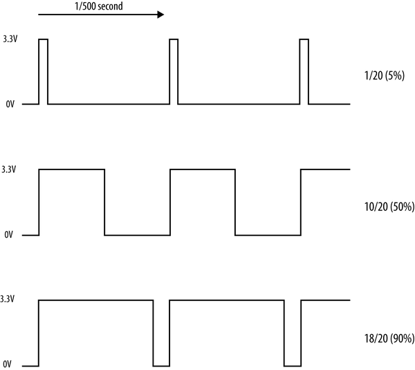
Figure 10-2. Pulse-width modulation
At high frequencies, the measured PWM frequency varies somewhat from the frequency supplied as an argument. This might change in later versions of the PWM feature of RPi.GPIO.
You can change the PWM frequency by modifying this line:
pwm_led=GPIO.PWM(led_pin,500)
The value is in Hz, so in this case, the frequency is set to 500 Hz.
Table 10-2 compares frequencies specified in the second parameter to GPIO.PWM to the actual frequency on the pin measured with an oscilloscope.
| Requested frequency | Measured frequency |
|---|---|
|
50 Hz |
50 Hz |
|
100 Hz |
98.7 Hz |
|
200 Hz |
195 Hz |
|
500 Hz |
470 Hz |
|
1 kHz |
890 Hz |
|
10 kHz |
4.4 kHz |
I also found that as the frequency increased, its stability decreased. This means that this PWM feature is no good for audio but plenty fast enough for controlling the brightness of LEDs or the speed of motors.
See Also
For more information on PWM, see Wikipedia.
Recipe 10.10 uses PWM to change the color of an RGB LED, and Recipe 11.4 uses PWM to control the speed of a DC motor.
For more information on using breadboard and jumper wires with the Raspberry Pi, see Recipe 9.8. You can also control the brightness of the LED with a slider control—see Recipe 10.9.
For another approach to controlling the color of an RGB LED using the Squid RGB LED library, see Recipe 9.10.
10.4 Make a Buzzing Sound
Solution
Use a piezo-electric buzzer connected to a GPIO pin.
Most small piezo buzzers work just fine using the arrangement shown in Figure 10-3. The one I used is an Adafruit-supplied component (see “Miscellaneous”). You can connect the buzzer pins directly to the Raspberry Pi using female-to-female headers (see “Prototyping Equipment”).
These buzzers use very little current. However, if you have a large buzzer or just want to play it safe, then put a 470Ω resistor between the GPIO pin and the buzzer lead.
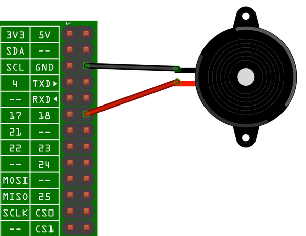
Figure 10-3. Connecting a piezo buzzer to a Raspberry Pi
Paste the following code into the IDLE (Recipe 5.2) or nano (Recipe 3.6) editors. Save the file as buzzer.py. You can also download the program from the Downloads section of the Raspberry Pi Cookbook website.
importRPi.GPIOasGPIOimporttimebuzzer_pin=18GPIO.setmode(GPIO.BCM)GPIO.setup(buzzer_pin,GPIO.OUT)defbuzz(pitch,duration):period=1.0/pitchdelay=period/2cycles=int(duration*pitch)foriinrange(cycles):GPIO.output(buzzer_pin,True)time.sleep(delay)GPIO.output(buzzer_pin,False)time.sleep(delay)whileTrue:pitch_s=raw_input("Enter Pitch (200 to 2000): ")pitch=float(pitch_s)duration_s=raw_input("Enter Duration (seconds): ")duration=float(duration_s)buzz(pitch,duration)
When you run the program, it will first prompt you for the pitch in Hz and then the duration of the buzz in seconds:
$ sudo python buzzer.py
Enter Pitch (2000 to 10000): 2000
Enter Duration (seconds): 20
Discussion
Piezo buzzers don’t have a wide range of frequencies, nor is the sound quality remotely good. However, you can vary the pitch a little. The frequency generated by the code is very approximate.
The program works by simply toggling the GPIO pin 18 on and off with a short delay in between. The delay is calculated from the pitch. The higher the pitch (frequency), the shorter the delay needs to be.
See Also
You can find the datasheet for the piezo buzzer here: http://bit.ly/Iwkv2R.
10.5 Switching a High-Power DC Device Using a Transistor
Solution
These high-power LEDs use far too much current to light directly from a GPIO pin. They also require 12V rather than the 3.3V. To control such a high-power load, you need to use a transistor.
In this case, you will use a high-power type of transistor called a metal–oxide–semiconductor field-effect transistor (MOSFET), which costs less than a dollar but can handle loads up to 30 amps—many times more than is required for the high-power LEDs. The MOSFET used is a FQP30N06L (see “Transistors and Diodes”).
Figure 10-4 shows how you can connect a MOSFET on a breadboard. Make sure that you correctly identify the positive and negative supply leads for the LED module.
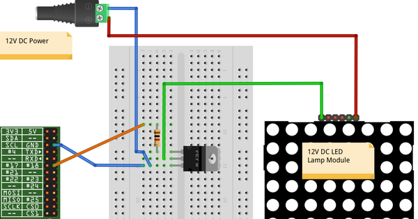
Figure 10-4. Controlling large currents with a MOSFET
To make this recipe, you will need:
-
Breadboard and jumper wires (see “Prototyping Equipment”)
-
1kΩ resistor (see “Resistors and Capacitors”)
-
FQP30N06L N-Channel MOSFET or TIP120 Darlington transistor (see “Transistors and Diodes”)
-
12V power adapter
-
12V DC LED module
The Python code to turn the LED panel on and off is exactly the same as if we were controlling a single low-power LED without the MOSFET (see Recipe 10.1).
You can also use PWM with the MOSFET to control the brightness of the LED module (see Recipe 10.3).
Discussion
Whenever you need to power anything significant using the GPIO connector, use batteries or an external power adapter. The GPIO connector can only supply relatively low currents (Recipe 9.2). In this case, you’ll use a 12V DC power adapter to provide the power to the LED panel. Pick a power adapter that has sufficient power handling. Therefore, if the LED module is 5W, then you need at least a 12V 5W power supply (6W would be better). If the power supply specifies a maximum current rather than power, then you can calculate its power by multiplying the voltage by the maximum current. Therefore, a 500mA 12V power supply can provide 6W of power.
The resistor is necessary to ensure that the peak currents that occur as the MOSFET switches from off to on and vice versa do not overload the GPIO pin. The MOSFET switches the negative side of the LED panel, so the positive supply is connected directly to the positive side of the LED panel, and the negative side of the LED panel is connected to the drain of the MOSFET. The source connection of the MOSFET is connected to GND, and the MOSFET’s gate pin controls the flow of current from the drain to the source. If gate voltage is above 2V or so, the MOSFET will turn on and current flows through both it and the LED module.
The MOSFET used here is a FQP30N06L. The L at then end means that it is a logic-level MOSFET whose gate threshold voltage is suitable for use with 3.3V digital outputs. The non-L version of this MOSFET is also likely to work just fine, but you cannot guarantee it as the specified range of gate threshold voltages is 2V to 4V. Therefore, if you were unlucky and got a MOSFET at the 4V end, it would not switch well.
An alternative to using a MOSFET is to use a power Darlington transistor like the TIP120. This has a compatible pinout with the FQP30N06L, so you can keep the same breadboard layout.
This circuit is suitable for controlling the power to other low-voltage DC devices. The only real exceptions are motors and relays, which require some extra treatment (see Recipe 10.6).
See Also
Check out the datasheet for the MOSFET.
If you would like to create a graphical user interface with which to control your LED module, see Recipe 10.8 for simple on/off control, and Recipe 10.9 for variable control of the brightness with a slider.
10.6 Switching a High-Power Device Using a Relay
Solution
Use a relay and small transistor.
Figure 10-5 shows how you can connect a transistor and relay on a breadboard. Make sure that both the transistor and diode are placed the right way. The diode has a stripe at one end, and the transistor used here has one side flat and one curved.
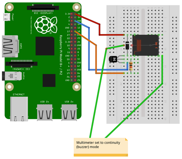
Figure 10-5. Using a relay with a Raspberry Pi
To make this recipe, you will need:
-
Breadboard and jumper wires (see “Prototyping Equipment”)
-
1kΩ resistor (see “Resistors and Capacitors”)
-
Transistor 2N3904 (see “Transistors and Diodes”)
-
1N4001 diode (see “Transistors and Diodes”)
-
5V relay (see “Miscellaneous”)
-
Multimeter
You can use the same LED blink program that you used in Recipe 10.1. If all is well, you’ll hear a click from the relay each time the contacts are closed. However, relays are slow mechanical devices, so don’t try to use them with PWM. It may damage the relay.
Discussion
Relays have been around since the early days of electronics and have the great advantage of being easy to use, plus they’ll work in any situation where a switch would normally work—for example, when you’re switching AC (alternating current) or in situations where the exact wiring of the device being switched is unknown.
If the relay contacts are asked to exceed their specifications, then the relay’s life will be shortened. There will be arcing, and the contacts may eventually fuse together. There is also the possibility of the relay becoming dangerously hot. When in doubt, overspecify the relay contacts.
Figure 10-6 shows the schematic symbol, pin layout, and package of a typical relay.
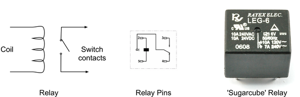
Figure 10-6. The workings of a relay
A relay is essentially a switch whose contacts are closed when an electromagnet pulls them together. Since the electromagnet and switch are not connected electrically in any way, this protects the circuit driving the relay coil from any high voltages on the switch side.
The downside of relays is that they are slow to operate and will eventually wear out after many hundreds of thousands of operations. This means they are only suitable for slow on/off control, and not for fast switching like PWM.
The coil of a relay requires about 50mA to close the connections. Because a Raspberry Pi GPIO pin is only capable of supplying about 3mA, you need to use a small transistor as a switch. You don’t need to use a high-power MOSFET like you did in Recipe 10.5, but instead you can just use a small transistor. This has three connections. The base (middle lead) is connected to the GPIO pin via a 1kΩ resistor to limit the current. The emitter is connected to GND, and the collector is connected to one side of the relay. The other side of the relay is connected to 5V on the GPIO connector. The diode is used to suppress any high-voltage pulses that occur when the transistor rapidly switches the power to the relay’s coil.
Warning
Although relays can be used to switch 110V or 240V AC, this voltage is very dangerous and should not be used on a breadboard. If you want to switch high voltages, use Recipe 10.7 instead.
See Also
For switching DC using a power MOSFET, see Recipe 10.5.
10.7 Controlling High-Voltage AC Devices
Solution
Use a PowerSwitch Tail II (see Figure 10-7). This handy device makes it really easy to switch AC equipment on and off from a Raspberry Pi. It has an AC socket on one end and a plug on the other, like an extension cable; the only difference is that the control box in the middle of the lead has three screw terminals. By attaching terminal 2 to GND and terminal 1 to a GPIO pin, the device acts like a switch to turn the appliance on and off.
You can use the same Python code that you did in Recipe 10.1 to use the PowerSwitch Tail, as shown in Figure 10-7.
Discussion
The PowerSwitch Tail uses a relay, but to switch the relay, it uses a component called an opto-isolator, which has an LED shining onto a photo-TRIAC (a high-voltage, light-sensitive switch); when the LED is illuminated, the photo-TRIAC conducts, supplying current to the relay coil.
The LED inside the opto-isolator has its current limited by a resistor so that only 3mA flows through it when you supply it with 3.3V from a GPIO pin.
You will also find similar but cheaper devices to the PowerSwitch Tail for sale on eBay and Amazon.
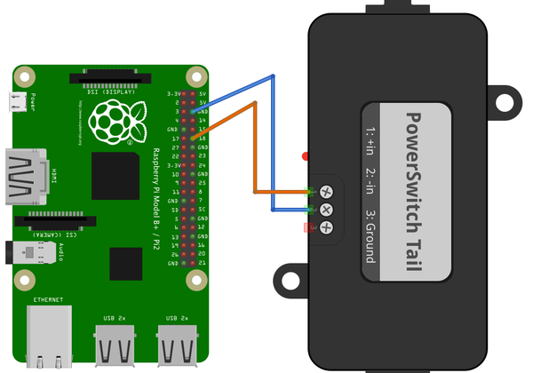
Figure 10-7. Using a PowerSwitch Tail with Raspberry Pi
See Also
For switching DC using a power MOSFET, see Recipe 10.5; and for switching using a relay on a breadboard, see Recipe 10.6.
A 240V version of the PowerSwitch Tail is available as a kit.
10.8 Making a User Interface to Turn Things On and Off
Solution
Using the Tkinter user interface framework, write a Python program that uses a checkbox to turn the GPIO pin on and off (Figure 10-8).
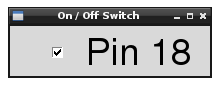
Figure 10-8. A user interface for turning things on and off
You’ll need to connect an LED or some other kind of output device to GPIO pin 18. Using an LED (Recipe 10.1) is the easiest option to start with.
Open an editor (nano or IDLE) and paste in the following code. As with all the program examples in this book, you can also download the program from the Code section of http://www.raspberrypicookbook.com, where it is called gui_switch.py.
fromTkinterimport*importRPi.GPIOasGPIOimporttimeGPIO.setmode(GPIO.BCM)GPIO.setup(18,GPIO.OUT)classApp:def__init__(self,master):frame=Frame(master)frame.pack()self.check_var=BooleanVar()check=Checkbutton(frame,text='Pin 18',command=self.update,variable=self.check_var,onvalue=True,offvalue=False)check.grid(row=1)defupdate(self):GPIO.output(18,self.check_var.get())root=Tk()root.wm_title('On / Off Switch')app=App(root)root.geometry("200x50+0+0")root.mainloop()
Note that you will need to run it with sudo because the RPi.GPIO requires you to have superuser privileges to access the GPIO hardware:
$ sudo python gui_switch.py
Tip
In Python 3, the Tkinter library has been renamed tkinter with a lowercase t.
Discussion
The example program defines a class called App that contains most of the application code. Its initializer function creates a member variable called check_var that contains an instance of BooleanVar that is then supplied as the variable option to the checkbox. This ensures that every time the checkbox is clicked, the value in this variable will be changed. The command option runs the update command every time such a change occurs.
The update function simply writes the value in check_var to the GPIO output.
See Also
You can use this program to control an LED (Figure 10-8), a high-power DC device (Recipe 10.5), a relay (Recipe 10.6), or a high-voltage AC device (Recipe 10.7).
10.9 Making a User Interface to Control PWM Power for LEDs and Motors
Solution
Using the Tkinter user interface framework, write a Python program that uses a slider to change the PWM duty cycle between 0 and 100 percent (Figure 10-9).
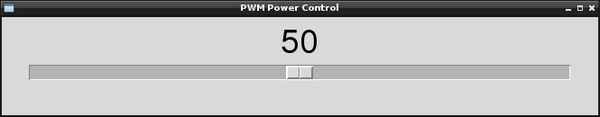
Figure 10-9. User interface for controlling PWM power
You will need to connect an LED or some other kind of output device to GPIO pin 18 that is capable of responding to a PWM signal. Using an LED (Recipe 10.1) is the easiest option to start with.
Open an editor (nano or IDLE) and paste in the following code. As with all the program examples in this book, you can also download the program from the Code section of http://www.raspberrypicookbook.com, where it is called gui_slider.py.
fromTkinterimport*importRPi.GPIOasGPIOimporttimeGPIO.setmode(GPIO.BCM)GPIO.setup(18,GPIO.OUT)pwm=GPIO.PWM(18,500)pwm.start(100)classApp:def__init__(self,master):frame=Frame(master)frame.pack()scale=Scale(frame,from_=0,to=100,orient=HORIZONTAL,command=self.update)scale.grid(row=0)defupdate(self,duty):pwm.ChangeDutyCycle(float(duty))root=Tk()root.wm_title('PWM Power Control')app=App(root)root.geometry("200x50+0+0")root.mainloop()
Note that you will need to run it with sudo because the RPi.GPIO requires you to have superuser privileges to access the GPIO hardware.
$ sudo python gui_slider.py
Discussion
The example program defines a class called App that contains most of the application code. The command option runs the update command every time the value of the slider is changed. This updates the duty cycle of the output pin.
See Also
You can use this program to control an LED (Recipe 10.1), a DC motor (Recipe 11.4), or a high-power DC device (Recipe 10.5).
10.10 Changing the Color of an RGB LED
Solution
Use PWM to control the power to each of the red, green, and blue channels of an RGB LED.
To make this recipe, you will need:
-
Breadboard and jumper wires (see “Prototyping Equipment”)
-
Three 470Ω resistors (see “Resistors and Capacitors”)
-
RGB common cathode LED (“Opto-Electronics”)
-
A Perma-Proto (Recipe 9.9) or Pi Plate (see Recipe 9.19) to make a more permanent project (optional)
Figure 10-10 shows how you can connect your RGB LED on a breadboard. Make sure that the LED is the correct way around; the longest lead should be the second lead from the top of the breadboard. This connection is called the common cathode, as the negative connections (cathodes) of the red, green, and blue LEDs within the LED case have all their negative sides connected together to reduce the number of pins needed in the package.
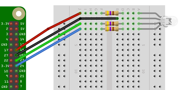
Figure 10-10. Using a RGB LED with a Raspberry Pi
An alternative to using a breadboard is to use a Raspberry Squid (see Recipe 9.10).
The upcoming program has three sliders to control the red, green, and blue channels of the LED (Figure 10-11).
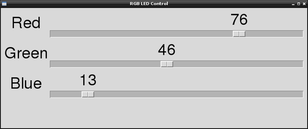
Figure 10-11. Using a user interface to control an RGB LED
Open an editor (nano or IDLE) and paste in the following code. As with all the program examples in this book, you can also download the program from the Code section of http://www.raspberrypicookbook.com, where it is called gui_sliderRGB.py.
fromTkinterimport*importRPi.GPIOasGPIOimporttimeGPIO.setmode(GPIO.BCM)GPIO.setup(18,GPIO.OUT)GPIO.setup(23,GPIO.OUT)GPIO.setup(24,GPIO.OUT)pwmRed=GPIO.PWM(18,500)pwmRed.start(100)pwmGreen=GPIO.PWM(23,500)pwmGreen.start(100)pwmBlue=GPIO.PWM(24,500)pwmBlue.start(100)classApp:def__init__(self,master):frame=Frame(master)frame.pack()Label(frame,text='Red').grid(row=0,column=0)Label(frame,text='Green').grid(row=1,column=0)Label(frame,text='Blue').grid(row=2,column=0)scaleRed=Scale(frame,from_=0,to=100,orient=HORIZONTAL,command=self.updateRed)scaleRed.grid(row=0,column=1)scaleGreen=Scale(frame,from_=0,to=100,orient=HORIZONTAL,command=self.updateGreen)scaleGreen.grid(row=1,column=1)scaleBlue=Scale(frame,from_=0,to=100,orient=HORIZONTAL,command=self.updateBlue)scaleBlue.grid(row=2,column=1)defupdateRed(self,duty):pwmRed.ChangeDutyCycle(float(duty))defupdateGreen(self,duty):pwmGreen.ChangeDutyCycle(float(duty))defupdateBlue(self,duty):pwmBlue.ChangeDutyCycle(float(duty))root=Tk()root.wm_title('RGB LED Control')app=App(root)root.geometry("200x150+0+0")root.mainloop()
Discussion
The code is similar in operation to the control for a single PWM channel, described in Recipe 10.9. However, in this case, you need three PWM channels and three sliders, one for each color.
The type of RGB LED used here is a common cathode. If you have the common anode type, then you can still use it, but connect the common anode to the 3.3V pin on the GPIO connector. You will then find that the slider becomes reversed, so a setting of 100 becomes off and 0 becomes full on.
When you are selecting an LED for this project, LEDs labeled diffused are best because they allow the colors to be mixed better.
See Also
If you just want to control one PWM channel, see Recipe 10.9.
For another approach to controlling the color of an RGB LED using the Squid RGB LED library, see Recipe 9.10.
10.11 Using Lots of LEDs (Charlieplexing)
Note
Be sure to check out the accompanying video for this recipe at http://razzpisampler.oreilly.com.
Solution
The way to do this is to use a technique called Charlieplexing. The name comes from the inventor, Charlie Allen of the company Maxim, and the technique takes advantage of the feature of GPIO pins that allows them to be changed from outputs to inputs while a program is running. When a pin is changed to be an input, not enough current will flow through it to light an LED or influence other pins connected to the LED that are set as outputs.
Figure 10-12 shows the schematic for controlling six LEDs with three pins.
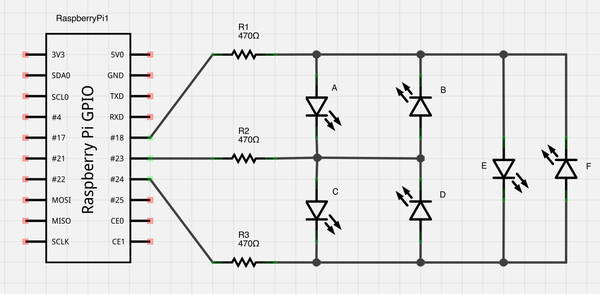
Figure 10-12. Charlieplexing
Figure 10-13 shows the breadboard layout for the LEDs and resistors.
To make this recipe, you will need:
-
Breadboard and jumper wires (see “Prototyping Equipment”)
-
Three 470Ω resistors (see “Resistors and Capacitors”)
-
Six LEDs (see “Opto-Electronics”)
Open an editor (nano or IDLE) and paste in the following code. As with all the program examples in this book, you can also download the program from the Code section of the Raspberry Pi Cookbook website, where it is called charlieplexing.py.
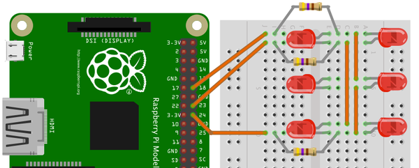
Figure 10-13. Charlieplexing breadboard layout
This example code prompts you to enter a number between 0 and 5, which then lights one of the six LEDs:
importRPi.GPIOasGPIOpins=[18,23,24]pin_led_states=[[1,0,-1],# A[0,1,-1],# B[-1,1,0],# C[-1,0,1],# D[1,-1,0],# E[0,-1,1]# F]GPIO.setmode(GPIO.BCM)defset_pin(pin_index,pin_state):ifpin_state==-1:GPIO.setup(pins[pin_index],GPIO.IN)else:GPIO.setup(pins[pin_index],GPIO.OUT)GPIO.output(pins[pin_index],pin_state)deflight_led(led_number):forpin_index,pin_stateinenumerate(pin_led_states[led_number]):set_pin(pin_index,pin_state)set_pin(0,-1)set_pin(1,-1)set_pin(2,-1)whileTrue:x=int(raw_input("Pin (0 to 5):"))light_led(x)
Discussion
To understand how Charlieplexing works, imagine that you want to light LED A in Figure 10-12. An LED will only light when its positive lead is high and its negative lead is low. If the voltage is the other way around, it will not light. To light LED A, you need its lead connected to GPIO 18 (via a resistor) to be high, and the other lead to LED A, connected to GPIO 23 by a resistor, to be low. However, you must also make sure that GPIO 24 is set to be an input; otherwise, LED C or D will also light depending on whether GPIO 24 is high or low.
The array pin_led_states holds the settings for each GPIO for each of the six LEDs. If the value is 0, the pin is low; 1 means high and -1 means set to be an input.
The number of LEDs that can be controlled per GPIO pin is given by the formula:
- LEDs = n2 - n
Using four pins, you can have 16, 4, or 12 LEDs, whereas 10 pins would give you a massive 90 LEDs.
In this example, you’re lighting only one LED at a time. To light more than one at a time, you need to run a refresh loop that keeps the desired state of the LEDs in an array and refreshes the display, turning on the LEDs that need to be on before moving on to the next. It must do this fast enough so that it appears that more than one of the LEDs is on at the same time.
The more LEDs you use when it comes to making it appear that more than one LED is on at a time, the less time the LED will actually be lit, and the dimmer the LEDs will become.
See Also
For more information about Charlieplexing, see Wikipedia.
10.12 Using an Analog Meter as a Display
Solution
Assuming you have a 5V volt meter, you can use a PWM output to drive the meter directly, connecting the negative side of the meter to ground and the positive side to a GPIO pin (Figure 10-14). If the meter is the common 5V kind, you’ll only be able to display voltages up to 3.3V.
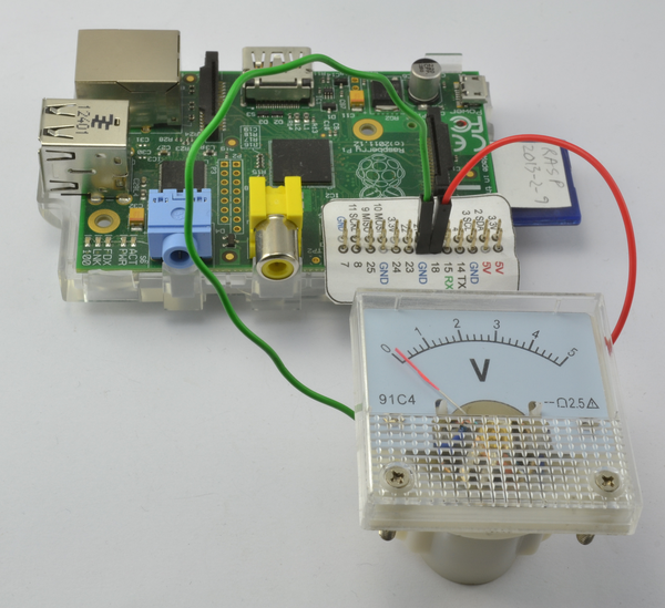
Figure 10-14. Connecting a volt meter directly to a GPIO pin
If you want to use almost the full range of a 5V volt meter, you will need a transistor to act as a switch for the PWM signal and a 1kΩ resistor to limit the current to the base of the transistor.
To make this recipe, you will need:
-
5V panel meter (“Miscellaneous”)
-
Breadboard and jumper wires (see “Prototyping Equipment”)
-
Two 1kΩ resistors (see “Resistors and Capacitors”)
-
Transistor 2N3904 (see “Transistors and Diodes”)
The breadboard layout for this is shown in Figure 10-15.
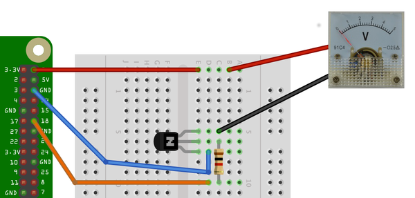
Figure 10-15. Using a 5V panel meter with 3.3V GPIO
Discussion
To test the volt meter, use the same program as you did for controlling the brightness of the LED in Recipe 10.9.
You will probably notice that the needle gives a steady reading at either end of the scale, but everywhere else it jitters a bit. This is a side effect of the way the PWM signals are generated. For a steadier result, you can use external PWM hardware like the 16-channel module used in Recipe 11.3.
See Also
For more information about how old-fashioned volt meters work, see Wikipedia.
For more information on using a breadboard and jumper wires with the Raspberry Pi, see Recipe 9.8.
10.13 Programming with Interrupts
Solution
Use the add_event_detect function of the RPi.GPIO library.
The upcoming example shows how you can attach an interrupt service routine to be triggered when a button is pressed.
Wire the switch onto a breadboard, as shown in Figure 10-16. Alternatively, you could use a Squid Button (Recipe 9.11).
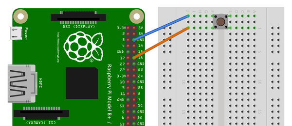
Figure 10-16. Connecting a switch to a GPIO input to demonstrate interrupts
Open an editor (nano or IDLE) and paste in the following code. As with all the program examples in this book, you can download the program from the Code section of the Raspberry Pi Cookbook website, where it is called interrupts.py.
This example code continually updates a count in seconds and displays a message when the button is pressed:
importRPi.GPIOasGPIOimporttimeGPIO.setmode(GPIO.BCM)defmy_callback(channel):('You pressed the button')GPIO.setup(18,GPIO.IN,pull_up_down=GPIO.PUD_UP)GPIO.add_event_detect(18,GPIO.FALLING,callback=my_callback)i=0whileTrue:i=i+1(i)time.sleep(1)
Try running the program with superuser privileges—you should see something like this happen when you press the button:
$ sudo python interrupts.py
1
2
3
You pressed the button
4
You pressed the button
5
You pressed the button
You pressed the button
6
Discussion
You could detect when a button has been pressed or a GPIO input has changed by simply checking repeatedly in a loop; for example:
whileTrue:ifGPIO.input(18)==False:# put the code to be actioned heretime.sleep(0.1)
The disadvantage here is that you can’t do much else while you are checking for button presses. A second disadvantage is that if the button press is very quick, it could come and go before you can register it with the GPIO.input. This approach is called polling.
Interrupts work differently. They allow you to associate a function with one of the pins so that when the voltage at the input changes either from low to high or vice versa, you can trigger the function to be run.
You can see how this works in the preceding example program. First, define a function called my_callback that takes a single argument. This argument specifies the input that triggered the interrupt, allowing you to use the same handler function for a number of interrupts.
defmy_callback(channel):('You pressed the button')
In this case, the callback function just displays a message.
The line of code that does the actual linking is:
GPIO.add_event_detect(18,GPIO.FALLING,callback=my_callback)
The first parameter specifies the pin (18). The second can be GPIO.FALLING or GPIO.RISING. If this is set to FALLING, the function will only be called if the GPIO pin goes from high to low. This is the case in this example, as the switch pulls the input low against the internal pull-up resistor. If, on the other hand, the second argument is set to RISING, the function will only be called when the input goes from low to high (when the switch is released).
The event handler function does not stop the main counting loop while it runs; it actually runs in its own separate thread of execution.
Switches often bounce when pressed. This means they don’t always transition cleanly from open to closed but bounce between the two, possibly several times, making it appear that the button was pressed multiple times in very rapid succession when actually it was pressed only once.
If you keep pressing the button, you’ll probably see this reflected in the output as the message appearing more than once for one button press.
The library actually has an option to stop bounce from being a problem, by preventing the interrupt from being triggered again within a certain amount of time. To make use of this feature, just add the extra optional parameter bouncetime to the add_event_detect call. The value of bouncetime is in milliseconds.
GPIO.add_event_detect(18, GPIO.FALLING, callback=my_callback, bouncetime=100)
See Also
For more information on using switches with the Raspberry Pi, see Recipe 12.1.