Table of Contents for
Raspberry Pi Cookbook, 2nd Edition
 Raspberry Pi Cookbook, 2nd Edition
Published by
O'Reilly Media, Inc., 2016
Raspberry Pi Cookbook, 2nd Edition
Published by
O'Reilly Media, Inc., 2016
- nav
- Cover
- Raspberry Pi Cookbook
- Raspberry Pi Cookbook
- Preface to the Second Edition
- Setup and Management
- Networking
- Operating System
- Software
- Python Basics
- Python Lists and Dictionaries
- Advanced Python
- Computer Vision
- Hardware Basics
- Controlling Hardware
- Motors
- Digital Inputs
- Sensors
- Displays
- The Internet of Things
- Arduino and Raspberry Pi
- Parts and Suppliers
- Raspberry Pi Pinouts
- Index
- About the Author
- Colophon
Chapter 9. Hardware Basics
9.0 Introduction
This chapter contains some basic recipes for setting up and using the Raspberry Pi’s general-purpose input/output (GPIO) connector. This connector allows you to connect all sorts of interesting electronics to your Raspberry Pi.
9.1 Finding Your Way Around the GPIO Connector
Note
Be sure to check out the accompanying video for this recipe at http://razzpisampler.oreilly.com.
Solution
There have actually been three versions of the Raspberry Pi GPIO connector. Two 26-pin layouts for the original Raspberry Pi and one 40-pin layout that came in with the Raspberry Pi “+” models.
Figure 9-1 shows the GPIO pinout for revisions 1 and 2 of the original Raspberry Pi Model B. The quick way to distinguish the boards is knowing that if you have one of the very first revision 1 boards, it has a black audio socket. The revision 2 boards have a blue audio socket.
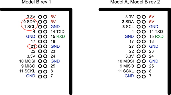
Figure 9-1. The GPIO pinout (26-pin models)
There were three changes to the GPIO connector between revision 1 and revision 2. These are highlighted in Figure 9-1. First, the I2C port was swapped. The two pins SDA and SCL are still SDA and SCL but use a different internal I2C interface. This means that if you’re using the pins as GPIO rather than I2C, then you will refer to them as 2 and 3 on a revision 2 board. Also, GPIO 21 was replaced by GPIO 27 on revision 2.
At the top of the connector, there are 3.3V and 5V power supplies. The GPIO uses 3.3V for all inputs and outputs. Any pin with a number next to it can act as a GPIO pin. Those that have another name after them also have some other special purpose, so 14 TXD and 15 RXD are the transmit and receive pins of the serial interface. SDA and SCL form the I2C interface, and MOSI, MISO, and SCKL from the SPI interface.
Figure 9-2 shows the current 40-pin layout, which is the same for all 40-pin GPIO Raspberry Pi models.
The top 26 pins are the same as the 26 pins of the original Raspberry Pi Model B revision 2. This allows the 40-pin Raspberry Pi models to use hardware and software designed for the earlier 26-pin Raspberry Pi designs. The extra pins of the 40-pin connector are made up of three useful extra GND connections and 9 GPIO pins. The ID_SD and ID_SC pins are intended for use in communicating with a special serial memory chip, which can be included on interface boards that conform to the Hardware At Top (HAT) standard and allows the Raspberry Pi to identify the board (see Discussion, next).
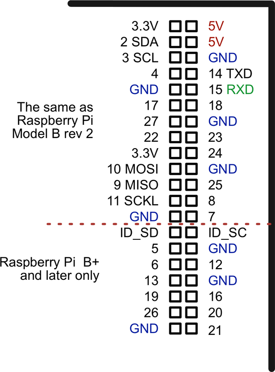
Figure 9-2. The GPIO pinout (40-pin models)
Discussion
Working out which pin is which on a Raspberry Pi is quite error-prone if you rely on counting down the pin connector to find the pin you need. A better way of finding the right pin is to use a GPIO template like the Raspberry Leaf shown in Figure 9-3.
This paper template fits over the GPIO pins telling you which is which. Other GPIO templates include the Pi GPIO Reference Board.
The Hardware At Top standard is an interface standard that you can use with the Raspberry Pi 2, B+ and A+. This standard does not in any way stop you from just using GPIO pins directly; however, interface boards that conform to the HAT standard can call themselves HATs and differ from regular Raspberry Pi interface boards in that a HAT must contain a little Electrically Erasable Programmable Read-Only Memory (EEPROM) chip that is used to identify the HAT so that ultimately the Raspberry Pi can auto-install necessary software. At the time of writing, HATs have not quite met that level of sophistication, but the idea is a good one. The pins ID_SD and ID_SC are used to communicate with a HAT EEPROM.
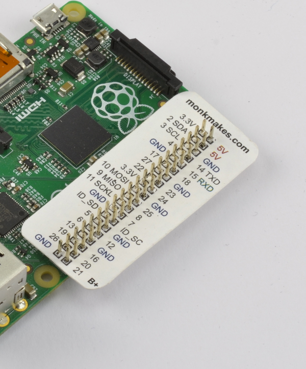
Figure 9-3. The Raspberry Leaf
See Also
The Raspberry Pi GPIO connector only has digital inputs and outputs; it does not have the analog inputs found on some similar boards. You can get around this short-coming by using a separate ADC chip (Recipe 13.5) or using resistive sensors (Recipe 13.1).
For an example of a HAT, see the Sense HAT described in Recipe 9.16.
9.2 Keeping Your Raspberry Pi Safe When Using the GPIO Connector
Solution
Obey these simple rules to reduce the risk of damaging your Raspberry Pi when using the GPIO connector:
-
Do not put more than 3.3V on any GPIO pin being used as an input.
-
Do not draw more than 16mA per output and keep the total for all outputs below 50mA in total for an older 26-pin Raspberry Pi, and below 100mA on a 40-pin Raspberry Pi.
-
When using LEDs, 3mA is enough to light a red LED reasonably brightly with a 470Ω series resistor.
-
Do not poke at the GPIO connector with a screwdriver or any metal object when the Pi is powered up.
-
Do not power the Pi with more than 5V.
-
Do not draw more than a total of 250mA from the 5V supply pins.
Discussion
There is no doubt about it, the Raspberry Pi is a little fragile when it comes to adding external electronics. The newer Raspberry Pi models are a little more robust but still quite easy to break. Exercise caution and check what you have done before you power up the Raspberry Pi, or you run the risk of having to replace your Raspberry Pi.
See Also
Read this very good discussion of the Raspberry Pi’s GPIO output capabilities.
9.3 Setting Up I2C
Solution
In the latest versions of Raspbian, enabling I2C is simply a matter of using the Raspberry Pi Configuration tool that you will find on the main menu under Preferences (Figure 9-4). Just check the box for I2C and click OK. You will be prompted to restart.
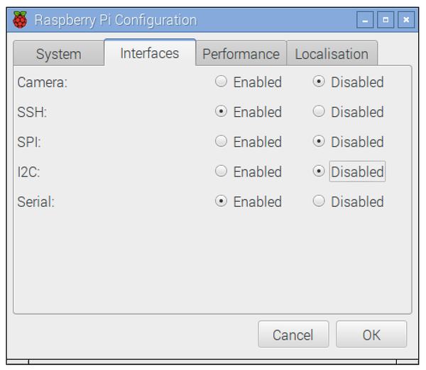
Figure 9-4. Enabling I2C using the Pi Configuration tool
On older versions of Raspbian, the raspi-config tool does the same job.
Start raspi-config using the following command:
$ sudo raspi-config
Then select Advanced from the menu and scroll down to I2C (Figure 9-5).
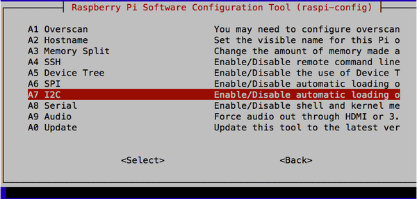
Figure 9-5. Enabling I2C using raspi-config
You will then be asked “Would you like the ARM I2C interface to be enabled?”, to which you should say “Yes.” You will also be asked if you want the I2C module loading at startup, to which you should also say “Yes.”
At this point, you will probably also want to install the Python I2C library by using the command:
$ sudo apt-get install python-smbus
You will then need to reboot the Raspberry Pi for the changes to take effect.
Discussion
Using I2C modules is actually a really good way of interfacing with the Pi. It reduces the number of wires that you need to connect everything (to just four), and there are some really neat I2C modules available.
However, don’t forget to calculate the total of the current used by the I2C modules and make sure that it doesn’t exceed those specified in Recipe 9.2.
Figure 9-6 shows a selection of I2C modules available from Adafruit. Other suppliers, such as SparkFun, also have I2C devices. From left to right, there are LED matrix displays; a four-digit, seven-segment LED display; a 16-channel PWM/servo controller; and a real-time clock module.
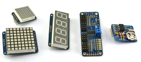
Figure 9-6. I2C modules
Other I2C modules include FM radio transmitters, ultrasonic rangefinders, OLED displays, and various types of sensors.
9.4 Using I2C Tools
Solution
Install and use i2c-tools.
Tip
On newer distributions, you may find that i2c-tools is already installed.
From a Terminal window on your Pi, type the following commands to fetch and install the i2c-tools:
$ sudo apt-get install i2c-tools
Attach your I2C device to the Pi and run the command:
$ sudo i2cdetect -y 1
Note that if you are using a very old Raspberry Pi revision 1 board, you need to change 1 to 0 in the preceding line of code.
If I2C is available, you will see some output like that shown in Figure 9-7. This shows that two I2C addresses are in use—0x68 and 0x70.
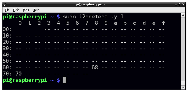
Figure 9-7. i2C-tools
See Also
See some of the I2C recipes in this book, including Recipes 11.3, 14.1, 14.2, and 14.4.
For more information on installing with apt-get, see Recipe 3.16.
9.5 Setting Up SPI
Solution
By default, Raspbian is not configured for the Raspberry Pi’s SPI interface to be enabled. To enable it, the procedure is almost the same as Recipe 9.3. Use the Raspberry Pi Configuration tool that you will find on the main menu under Preferences, or on older versions of Raspbian, use the raspi-config using the command:
$ sudo raspi-config
Then select Advanced, followed by SPI, and then Yes before rebooting your Raspberry Pi. After the reboot, SPI will be available.
Discussion
SPI allows serial transfer of data between the Raspberry Pi and peripheral devices, such as analog-to-digital converter (ADC) and port expander chips, among other devices.
You may come across some examples of interfacing to SPI that do not use the SPI interface but instead use an approach called bit banging, where the RPi.GPIO library is used to interface with the four GPIO pins used by the SPI interface.
See Also
We use a SPI analog-to-digital converter chip in Recipe 13.5.
9.6 Installing PySerial for Access to the Serial Port from Python
Discussion
The library is pretty easy to use. Creating a connection uses the following syntax:
ser=serial.Serial(DEVICE,BAUD)
Where DEVICE is the device for the serial port (/dev/ttyAMA0) and BAUD is the baud rate as a number, not a string. For example:
ser=serial.Serial('/dev/ttyAMA0',9600)
Once a connection is established, you can send data over serial like this:
ser.write('some text')
Listening for a response normally involves a loop that reads and prints, as illustrated in this example:
whileTrue:(ser.read())
See Also
You will need to use this technique in recipes that connect hardware to the serial port, such as Recipe 12.10.
9.7 Installing Minicom to Test the Serial Port
Solution
$ sudo apt-get install minicom
Once Minicom is installed, you can start a serial communications session with a serial device connected to the RXD and TXD pins of the GPIO connector by using this command:
$ minicom -b 9600 -o -D /dev/ttyAMA0
The parameter after -b is the baud rate, and after -D, the serial port. Remember to use the same baud rate as the one on the device you are communicating with.
This will start a Minicom session. One of the first things you want to do is turn on local echo so you can see the command that you are typing. To do this, press Ctrl-A and then Z; you’ll see the command list shown in Figure 9-8. Press E to turn on local echo.
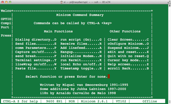
Figure 9-8. Minicom commands
Now anything you type will be sent to the serial device, and all messages coming from the device will also be displayed.
Discussion
Minicom is a great tool for checking out the messages coming from a serial device or making sure that it’s working.
See Also
Check out the Minicom documentation.
If you want to write a Python program to handle the serial communications, you will need the Python serial library (Recipe 9.6).
9.8 Using a Breadboard with Jumper Leads
Solution
Use male-to-female jumper wires and a GPIO pin label template like the Raspberry Leaf (Figure 9-9).
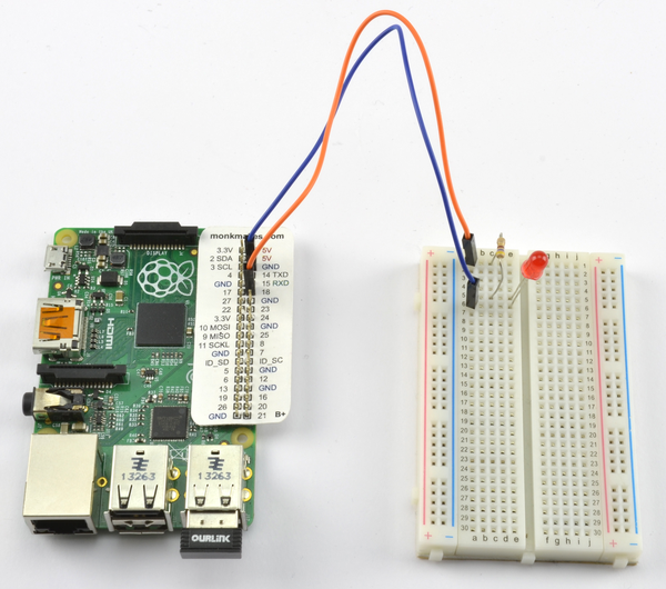
Figure 9-9. Connecting Pi to breadboard using male-to-female jumper wires
Discussion
It’s not always easy to identify the pins you want on a bare Raspberry Pi board. You can greatly simplify this by printing out a template, like the Raspberry Leaf, to fit over the pins.
It is also useful to have a selection of male-to-male jumper wires for making connections from one part of the breadboard to another.
Female-to-female jumper wires are useful for connecting modules with male header pins directly to the Raspberry Pi, when no other components might warrant the use of a breadboard.
A good way of getting a breadboard, Raspberry Leaf, and set of jumper wires is to buy a starter kit based around a breadboard like the Electronics Starter Kit for Raspberry Pi from MonkMakes (see Appendix A).
See Also
This approach works well when you have a small number of connections. When you have more to make, a Pi Cobbler is better (see Recipe 9.9).
9.9 Using a Breadboard with a Pi Cobbler
Solution
Use an Adafruit Pi Cobbler, a device consisting of a small printed circuit board (PCB) with header pins that are designed to fit into a solderless breadboard like a dual inline package (DIL) chip. The pins are all labeled and the PCB has a header socket. The supplied ribbon cable is used to link the Cobbler to the Raspberry Pi (see Figure 9-10).
The Pi Cobbler shown in Figure 9-10 is the 26-pin version of the product. There is also a 40-pin version designed for the newer Raspberry Pis, but this leaves little room on the breadboard for other components, so if you have enough GPIO pins for your project in the top 26 pins of the GPIO connector, then it can sometimes be better to use the 26-pin version of the Pi Cobbler even with a 40-pin Raspberry Pi.
Discussion
A great advantage of the Cobbler is that you can assemble the components onto the breadboard and then plug in the ribbon cable when it’s ready.
Make sure that the red edge of the ribbon cable is toward the SD card edge of the Raspberry Pi. The cable only fits into the socket on the Pi Cobbler the correct way around.
Once you have built your breadboard prototype, you might decide to make a soldered version of the prototype. A great way to do this is to use an Adafruit Perma-Proto board like the ones shown in Figure 9-11.
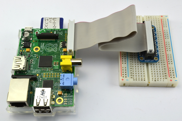
Figure 9-10. Connecting Pi to a breadboard using a Pi Cobbler
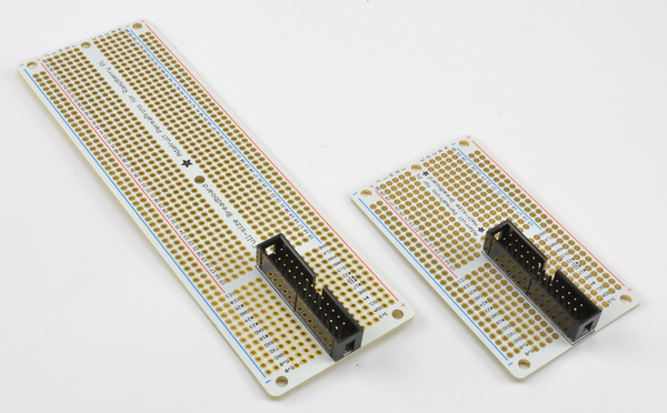
Figure 9-11. Adafruit Perma-Proto boards
These boards are ready-made Printed Circuit Boards (PCB) that have the same layout of tracks and holes as a breadboard. This allows you to transfer your breadboard design to the Perma-Proto board without having to redesign it. The board comes complete with a socket to accept the cable and plug of the Cobbler.
9.10 Using a Raspberry Squid
Solution
Use a Raspberry Squid RGB LED (Figure 9-12).
The Raspberry Squid is an RGB LED with built-in series resistors and female header leads, so that it can be plugged directly onto the GPIO pins of a Raspberry Pi. The Squid has color-coded leads. The black lead goes to one of the GPIO GND pins and the red, green, and blue leads go to GPIO pins used for the red, green, and blue channels. The red, green, and blue outputs can be simple digital outputs or PWM outputs (Recipe 10.3) that allow you to mix different colors.
Instructions for making your own Squid can be found at https://github.com/simonmonk/squid, but you can also buy ready-made Squid from http://monkmakes.com.
The Squid has a Python library that is installed using the following commands:
$ git clone https://github.com/simonmonk/squid.git
$ cd squid
$ sudo python setup.py install
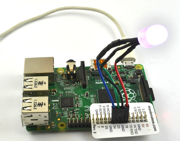
Figure 9-12. A Raspberry Squid
Inside the example folder, you will find the program test_led.py, which tells you pretty much all you need to know about using the Raspberry Squid.
fromsquidimport*importtimergb=Squid(18,23,24)rgb.set_color(RED)time.sleep(2)rgb.set_color(GREEN)time.sleep(2)rgb.set_color(BLUE)time.sleep(2)rgb.set_color(WHITE)time.sleep(2)rgb.set_color(WHITE,300)time.sleep(2)
Having imported the squid library, you can create a new Squid object, supplying the three pins to be used for its red, green, and blue channels (in this case, 18, 23, and 24). You can then set the color by using the set_color method, which takes either the name of a color constant (RED, GREEN, WHITE, etc.) or a tuple of three values each between 0 and 100 for the red, green, and blue channels. The optional second parameter to set_color is the overall brightness.
After the color is set, time.sleep(2) is used to create a two-second delay before the next color change.
Discussion
You do not need to use all three color channels of a Squid, and it can be quite handy to just check that a GPIO pin is turning on and off as you expect before attaching some other electronics to it.
See Also
For information on the Squid library, see https://github.com/simonmonk/squid.
For information on the Squid Button, see Recipe 9.11.
Recipe 10.10 is an example project that controls an RGB LED (Squid or breadboard-based).
9.11 Using a Raspberry Squid Button
Solution
Use a Squid Button.
The Squid Button (Figure 9-13) is a push button with female header leads connected to the contacts so that you can plug it directly into the GPIO connector of a Raspberry Pi. The Squid Button also includes a low-value resistor that limits the current that would flow if the Squid Button were to be accidentally connected to a digital output rather than a digital input.
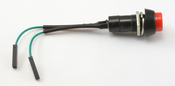
Figure 9-13. A Squid Button
The Squid Button is a natural companion to the Squid RGB LED and shares the same Python library (see Recipe 9.10 to install this library).
The Squid Button could be used directly with the RPi.GPIO library, but the squid library provides key debouncing (see https://github.com/simonmonk/squid) to prevent accidental multiple presses of the button. The file test_button.py in the examples folder of the squid library illustrates the use of the button.
frombuttonimport*importtimeb=Button(7)whileTrue:ifb.is_pressed():(time.time())
The number (in this case, 7) indicates the GPIO pin that the button is connected to. The other pin is connected to GND.
Discussion
The Squid button is useful for testing projects that use a digital input, but since the button is suitable for panel mounting, you can also build it into more permanent projects.
See Also
For information on the squid library, see https://github.com/simonmonk/squid.
For more information on using switches, see Recipes 12.1, 12.2, 12.3, 12.4, 12.5, and 12.6.
For information on the Squid RGB LED, see Recipe 9.10.
9.12 Converting 5V Signals to 3.3V with Two Resistors
Solution
Use a pair of resistors as a potential divider to reduce the output voltage. Figure 9-14 shows how you might use the 5V serial connection of an Arduino to a Raspberry Pi.
To make this recipe, you will need:
-
270Ω resistor (see “Resistors and Capacitors” in Appendix A)
-
470Ω resistor (see “Resistors and Capacitors” in Appendix A)
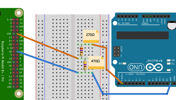
Figure 9-14. Using resistors to convert a 5V signal to 3.3V
The TXD signal from the Pi is a 3.3V output. This can be connected directly to a 5V input on the Arduino without any problem. The Arduino module will recognize anything over about 2.5V as being high.
The problem arises when you need to connect the 5V output of the Arduino module to the RXD pin of the Pi. This must not be connected directly to the RXD input. The 5V signal could damage the Pi. Instead, the two resistors shown in Figure 9-14 are used.
Discussion
The resistors used here will draw a current of 6mA. Given that the Pi uses a fairly hefty 500mA, this will not noticeably affect the current consumption of the Pi.
If you want to minimize the current used by the potential divider, then use larger value resistors, scaled proportionally—for example, 27kΩ and 47kΩ, which will draw a miserly 60 µA.
See Also
For more information on connecting Raspberry Pi to Arduino, see Chapter 16.
If you have multiple signals to convert between 3.3V and 5V, then it’s probably best to use a multichannel level converter module—see Recipe 9.13.
9.13 Converting 5V Signals to 3.3V with a Level Converter Module
Solution
Use a bidirectional level converter module, such as the ones shown in Figure 9-15.
These modules are very easy to use. One side has the power supply at one voltage and a number of channels that can be either inputs or outputs at that voltage. The pins on the other side of the module have a power pin at the second voltage, and all the inputs and outputs on that side are automatically converted to the voltage level for that side.
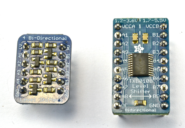
Figure 9-15. Level converter modules
Discussion
These level converters are available with differing numbers of channels. The two shown in Figure 9-15 have four and eight channels.
Sources for such level converters can be found in Appendix A.
See Also
See Recipe 9.12, especially if you have only one or two levels to convert.
Normally 5V logic inputs will accept 3.3V outputs without a problem, however in some cases, such as when using LED strips (Recipe 14.7), this may not be the case, in which case a transistor or one of the modules described above can be used to raise the logic level.
9.14 Powering a Raspberry Pi with Batteries
Solution
A typical project using a Raspberry Pi requires 5V at up to about 600mA (see Recipe 1.3). The requirement for 5V is strict. You should not try to power your Pi from more or less than 5V. In practice, this means you are most likely to use a battery at a higher voltage than 5V—say, 9V—and use a voltage regulator to drop the voltage to 5V.
The relatively high power requirement of the Pi makes it unsuitable for powering from, say, a small 9V battery or even a set of AAA batteries. Most suitable would be a pack made up of six rechargeable AA batteries and a voltage regulator.
Figure 9-16 shows how you can use a voltage regulator with a battery pack to power a Pi through the 5V pin on the GPIO connector.
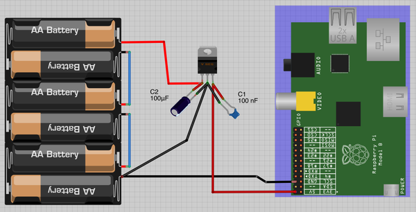
Figure 9-16. Powering a Raspberry Pi with AA batteries
The 7805 voltage regulator will get pretty hot. If it gets too hot, its thermal cutout will kick in and the voltage at its output will drop, probably causing the Pi to reset. A heat sink that clips onto the integrated circuit (IC) will help with this.
An alternative solution, and a cooler one, is to use a RasPiRobot Board V3 (Recipe 9.18), as shown in Figure 9-17.
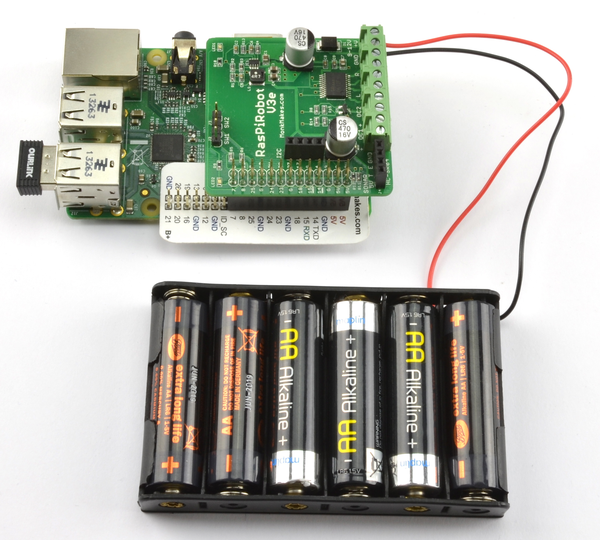
Figure 9-17. Powering a Raspberry Pi using a RasPiRobot Board V3
As well as being a motor driver, the RasPiRobot Board V3 has a built-in switched-mode power supply that will take an input of between 7V and 12V and supply the Raspberry Pi with 5V. Because the RasPiRobot Board V3 power supply is an efficient switching power supply rather than a linear regulator like the 7805, it will not get hot under normal use of the Raspberry Pi.
Discussion
The 7805 requires the input voltage to be at least 2V above 5V. You can also buy low dropout (LDO) regulators, such as the LM2940. The LM2940 has the same pinout as the 7805 but only requires the input to be 0.5V above the 5V output. However, remember that nominally, 1.5V AA cells soon drop to about 1.2V. So a pack of four of them is unlikely to provide enough voltage for more than a few minutes. A pack of six will be fine.
The example above uses a 9V battery pack, but if you want to fit your Raspberry Pi into an automobile or RV’s 12V supply, this recipe will still work. You will also need to use a small monitor that can be powered from direct current (DC). Such devices are fairly easily found, as they are commonly used with closed-circuit camera systems.
See Also
Another way to power your Raspberry Pi from a battery is to use a ready-made cellphone charger that accepts AA batteries. Make sure that it can cope with 600mA or more.
Recipe 9.15 shows you how to power a Raspberry Pi from a LiPo battery pack.
For more information on using the RasPiRobot Board V3, see Recipe 9.18.
9.15 Powering a Raspberry Pi with a LiPo Battery
Solution
Use a boost regulator module (Figure 9-18). The module shown is from SparkFun, but similar designs are available on eBay more cheaply.
As always with such low-cost purchases from eBay, you should test the module thoroughly before using it. They do not always work exactly as advertised, and quality can be quite variable.
The advantage of this kind of module is that it acts as both a voltage regulator to supply 5V to the Pi and also has a USB socket of its own to supply power to its charging circuit. If you plug the Pi’s power adapter into the socket on the charger, the Pi will be powered and the battery charged, allowing you to unplug the USB power and use the Pi on the battery for as long as it has enough power.
With a 1300mA LiPo battery, you could expect the Pi to be powered for two or three hours.
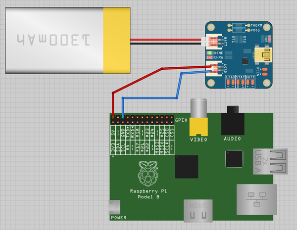
Figure 9-18. Powering a Raspberry Pi with a 3.7V LiPo battery
Discussion
If you plan to handle the charging of the battery elsewhere, you can just go for a boost converter module, without the charger, at a lower cost.
9.16 Getting Started with the Sense HAT
Solution
The Raspberry Pi Sense HAT (Figure 9-19) is a useful and somewhat confusingly named interface board for the Raspberry Pi. Yes, it includes sensors—in fact, it can measure temperature, relative humidity, and atmospheric pressure (Recipe 13.10). It also has an accelerometer, gyroscope (Recipe 13.13), and magnetometer (Recipe 13.14) for navigation type projects. It also has a full-color 8×8 LED matrix display (Recipe 14.3).
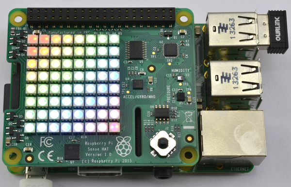
Figure 9-19. The Raspberry Pi Sense HAT
The Sense HAT requires a Raspberry Pi with a 40-pin GPIO header, so you will not be able to use it on an older Raspberry Pi with a 26-pin header.
The Sense HAT requires some software to be installed before you can use it. The process is not complicated, but it can take quite a while.
Note that by the time you read this, you might find that Raspbian already includes all the software that you need for the Sense HAT. If this is the case, running these commands will not cause any problems; the installer will just tell you that it has nothing to do.
Install the Sense HAT Python library by using the command:
$ sudo apt-get install sense-hat
This installer will actually enable I2C automatically, so you do not need to follow the usual I2C setup (Recipe 9.3).
The Sense HAT’s display uses a graphics library called Python Image Library (PIL), which must be installed by using the command:
$ sudo pip-3.2 install pillow
Installation will take a while, after which you should reboot if I2C was not already enabled.
Discussion
There are more recipes that use the Sense HAT in this book, but for now, you can just check that everything is working by opening a Python console using:
$ sudo python
Then enter the following commands into the Python console:
>>> from sense_hat import SenseHat
>>> hat = SenseHat()
>>> hat.show_message('The Raspberry Pi Cookbook')
The LED matrix should then display the text of the message above, scrolling it across the screen.
See Also
The programming reference for the Sense HAT, at https://pythonhosted.org/sense-hat/api/.
To measure temperature, humidity, and atmospheric pressure, see Recipe 13.10.
To use the Sense HAT’s accelerometer and gyroscope, see Recipe 13.13.
To use the magnetometer to detect north and detect the presence of a magnet, see Recipes 13.14 and 13.16, respectively.
9.17 Getting Started with the Explorer HAT Pro
Solution
Plug the HAT into your Raspberry Pi and install the Explorer HAT Pro Python library.
Figure 9-20 shows a Pimoroni Explorer HAT Pro on a Raspberry Pi B+. Note that this HAT will only work on a 40-pin Raspberry Pi.
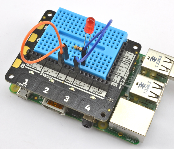
Figure 9-20. A Pimoroni Explorer HAT Pro
The Explorer HAT Pro has some useful input/output options as well as an area where a small solderless breadboard can be attached. Its features include:
- 4 LEDs
- 4 buffered inputs
- 4 buffered outputs (up to 500mA)
- 4 analog inputs
- 2 low-power motor drivers (max 200mA)
- 4 capacitative touch pads
- 4 capacitative crocodile clip pads
To install the Python library for the Explorer HAT Pro, run the following command:
$ sudo pip install explorerhat
Once the library is installed, you can try a little experiment to make the built-in red LED blink.
importexplorerhat,timewhileTrue:explorerhat.light.red.on()time.sleep(0.5)explorerhat.light.red.off()time.sleep(0.5)
Open an editor (nano or IDLE) and paste in the following code. As with all the program examples in this book, you can download the program from the Code section of the Raspberry Pi Cookbook website, where it is called explorer_blink.py.
Discussion
The Explorer HAT Pro provides four buffered inputs and outputs—that is inputs and outputs that are not connected directly to the Raspberry Pi, but to chips on the Explorer HAT Pro. This means that if you accidentally connect things incorrectly, the Explorer HAT Pro will be damaged rather than your Raspberry Pi.
See Also
You can use the Explorer HAT for capacitative touch sensing (Recipe 13.18).
9.18 Getting Started with a RaspiRobot Board
Solution
Figure 9-21 shows the RaspiRobot board (version 3). The board has a dual-motor controller that can be used for two DC motors or a single stepper motor. It can supply 5V power to the Raspberry Pi by using its built-in switched-mode voltage regulator. The board has two switch inputs and two high-current (2A) outputs, and provides easy connections to a HC-SR04 rangefinder and the I2C interfaces of the Raspberry Pi.
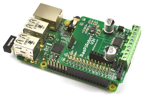
Figure 9-21. The RaspiRobot board V3
The RaspiRobot Board V3 has its own Python library that you need to download and install, using the following commands:
$ git clone https://github.com/simonmonk/raspirobotboard3.git
$ cd raspirobotboard3/python
$ sudo python setup.py install
Discussion
Fit your RasPiRobot V3 onto your Raspberry Pi and then power up the Raspberry Pi. You can try out a few commands with the RaspiRobot board, using just the Python console without attaching external power or motors to the RaspiRobot board. Since the RaspiRobot board library uses the GPIO port, you will need to start Python as a superuser by using this command:
$ sudo python
When you first power up, you should find that both LEDs on the RaspiRobot board will be lit. Now enter the following commands, and both LEDs should turn off as the library is initialized:
>>>fromraspirobotboardimport*>>>rr=RRB3()
Try turning one of the LEDs on and off, using these commands:
>>>rr.set_led1(1)>>>rr.set_led1(0)
The RaspiRobot board has two pairs of pins, each designed to be connected to a switch. These are labeled SW1 and SW2 on the board. You can test whether SW1 is closed by using the command:
>>>(rr.sw1_closed())False
Shorting the two pins of SW1 together with a screwdriver and issuing the command again will return True.
Other commands are available to set the two open collector outputs (set_oc1 and set_oc2) and motor control commands (forward, reverse, left, right, and stop). See http://www.raspirobot.com for the full command reference.
See Also
To learn how to use this board to make a roving robot, see Recipe 11.10.
To use the RaspiRobot board to control a bipolar stepper motor, see Recipe 11.9.
9.19 Using a Pi Plate Prototyping Board
Solution
The Pi Plate (Figure 9-22) is a prototyping board rather than an interface board like the RaspiRobot board (Recipe 9.18). In other words, it does not include any electronics—it is designed for you to solder your own components to a prototyping area.
The board has an area where a 16-pin, surface-mount chip can be used, and a row of four holes, spaced more widely, where a screw terminal can be soldered in place.
The board has screw terminals on two sides, which are connected to all the GPIO pins. You can ignore the prototyping area entirely and just use the screw terminals to attach wires to the GPIO pins.

Figure 9-22. The Pi Plate
Discussion
The board design has a grid of holes at a pitch of the standard 0.1 inch used by most through-hole components, including DIL ICs. You solder components to the board by pushing the leads through the holes at the top and soldering the connections underneath.
The tracks that connect the holes are clearly visible on the top of the board, and the board is divided into several zones. There is an area with central power busses intended for DIL ICs, as well as a general prototyping area and areas for a surface-mount chip and extra screw terminals.
Having soldered the components into place, you will need extra wires to link everything together. These can be run on the bottom or top of the board, or both if the design is complicated.
It’s a good idea to plan out the layout before you start soldering.
In the following instructions, you will build an RGB LED onto a Pi Plate, using the layout shown in Figure 9-23. This recipe is a version of Recipe 10.10, which is the same except that the design is built onto a solderless breadboard.
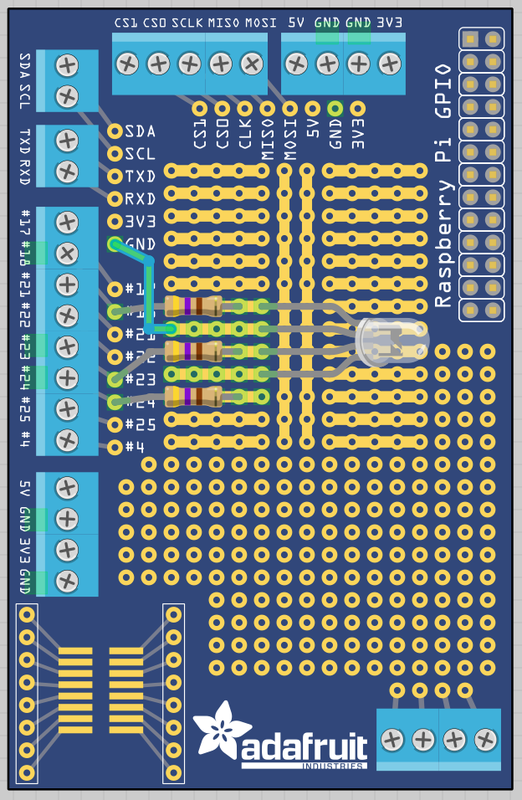
Figure 9-23. Board layout for an RGB LED on a Pi Plate
The first step is to solder the resistors into place. Bend the leads and push them through the appropriate holes in the board. Then flip the board over and touch the soldering iron to where the leads emerge from the holes for a second or so before applying the solder, which should flow around the lead (Figure 9-24).
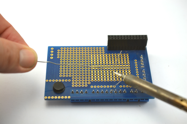
Figure 9-24. Soldering a resistor to the Pi Plate
When you have soldered both ends, snip off the excess lead and repeat for the other two resistors (Figure 9-25).
Now solder the LED into place, taking care to get it facing the right way. The longest lead is the common cathode and should be the only LED lead attached to the strip of holes that is not connected to any resistor. Very occasionally, you will find LEDs where the longer lead is not the positive lead. This is often the case with infrared LEDs. If you aren’t sure, check the datasheet for the LED or the supplier’s information page.
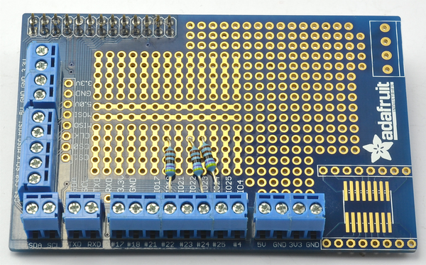
Figure 9-25. Resistors soldered to the Pi Plate
You will also need to solder a short length of wire from that row to the GND connection on the Pi Plate (Figure 9-26).
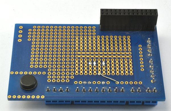
Figure 9-26. Soldering the link wire to the Pi Plate
When the board is complete, it should look like Figure 9-27.
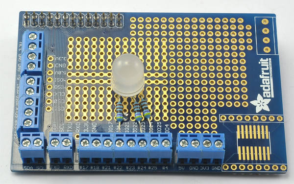
Figure 9-27. The finished RGB LED on a Pi Plate
You can try out the LED using the Python program from Recipe 10.10.
See Also
There is more information about this product at the Adafruit website.
9.20 Making a Hardware At Top (HAT)
Solution
Use a Perma-Proto Pi HAT (Figure 9-28).
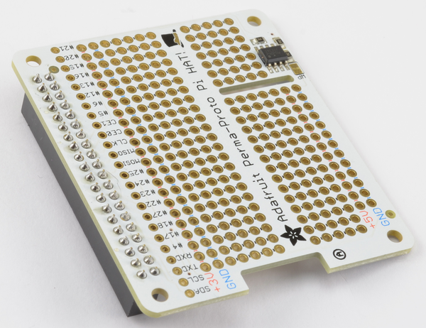
Figure 9-28. A Perma-Proto Pi HAT
With the advent of the Raspberry Pi B+ with a 40-pin GPIO header, a new standard for add-on boards for the Raspberry Pi was defined, called HAT (Hardware At Top). You do not have to stick to this standard, especially if you are just making a one-off product for yourself, but if you are designing a product to sell, then it may make sense for you to conform to the HAT standard.
The HAT standard defines the size and shape of the PCB and also mandates that the PCB has an Electrically Erasable Read-Only Memory (EEPROM) chip soldered onto the board. This chip is connected to the ID_SD and ID_SC pins of the GPIO header, and in the future will allow some configuration of the Pi and even automatic loading of software to occur when the Raspberry Pi is booted up with a HAT attached.
The prototyping area of the board is made up of some power rails and a breadboard format layout of two rows of five holes plus power rails down both sides of the board.
If you don’t care about programming the EEPROM, then you can stop here. However, if you want to add your own custom information onto the HAT’s EEPROM, then read on to the Discussion next.
Discussion
The HAT standard makes a lot of sense. However, at the time of writing, Raspbian does not make use of any information written in the HAT’s EEPROM. This is likely to change in the future and leads to the exciting possibility of HATs automatically doing things like enabling I2C and installing Python libraries for their hardware, just by being present on the Raspberry Pi.
To write data into the EEPROM, you first need to enable the hidden I2C port used by the ID_SD and ID_SC pins that are used to read and write to the EEPROM. To do that, you will need to edit /boot/config.txt by adding in or uncommenting the line:
dtparam=i2c_vc=on
Once this is done, reboot your Raspberry Pi, and you should then be able to detect that the I2C EEPROM is attached to the I2C bus using i2c tools (Recipe 9.4).
$ i2cdetect -y 0
     0  1  2  3  4  5  6  7  8  9  a  b  c  d  e  f
00:          -- -- -- -- -- -- -- -- -- -- -- -- --
10: -- -- -- -- -- -- -- -- -- -- -- -- -- -- -- --
20: -- -- -- -- -- -- -- -- -- -- -- -- -- -- -- --
30: -- -- -- -- -- -- -- -- -- -- -- -- -- -- -- --
40: -- -- -- -- -- -- -- -- -- -- -- -- -- -- -- --
50: 50 -- -- -- -- -- -- -- -- -- -- -- -- -- -- --
60: -- -- -- -- -- -- -- -- -- -- -- -- -- -- -- --
70: -- -- -- -- -- -- -- --
You can see from the result of the i2cdetect command that the EEPROM has an I2C address of 50. Note that the option -y 0 rather than the usual -y 1 is used because this is not the normal I2C bus on pins 2 and 3, but rather the I2C bus dedicated to the HAT EEPROM.
To read and write the EEPROM, you need to download some tools by using the commands below:
$ git clone https://github.com/raspberrypi/hats.git
$ cd hats/eepromutils
$ make
Writing the EEPROM is a three-step process. First, you must edit the file eeprom_settings.txt. Change at least the product_id, product_version, vendor, and product fields to be your company name and product name. Note that there are lots of other options in this file, which is well-documented. They include specifying back-powering options, GPIO pins used, etc.
Second, after editing the file, run the command below to convert the text file into a file suitable for writing to the EEPROM (rom_file.eep).
$ ./eepmake eeprom_settings.txt rom_file.eep
Opening file eeprom_settings.txt for read
UUID=7aa8b587-9c11-4177-bf14-00e601c5025e
Done reading
Writing out...
Done.
Finally, copy rom_file.eep onto the EEPROM by running the command below:
sudo ./eepflash.sh -w -f=rom_file.eep -t=24c32
This will disable the camera so you will need to REBOOT after this...
This will attempt to write to i2c address 0x50. Make sure there is...
This script comes with ABSOLUTELY no warranty. Continue only if you...
Do you wish to continue? (yes/no): yes
Writing...
0+1 records in
0+1 records out
127 bytes (127 B) copied, 2.52071 s, 0.1 kB/s
Done.
pi@raspberrypi ~/hats/eepromutils $
Once writing is complete, you can read the ROM back using the commands below:
$ sudo ./eepflash.sh -r -f=read_back.eep -t=24c32
$ ./eepdump read_back.eep read_back.txt
$ more read_back.txt
See Also
You can find the Raspberry Pi HAT design guide here: https://github.com/raspberrypi/hats.
There are many ready-made HATs on the market, including the Stepper Motor (Recipe 11.8), Capacitative Touch (Recipe 13.18), and 16-Channel PWM (Recipe 11.1) HATs from Adafruit, as well as the Pimoroni Explorer HAT Pro (Recipe 9.16).
9.21 The Pi Compute Module
Solution
Use a Raspberry Pi Compute module.
The Raspberry Pi Compute module (shown on the left of Figure 9-29 next to its IO board on the right) is a board containing the Raspberry Pi System on a Chip (SoC) with 512 MB RAM in the form factor of a SODIMM memory module such as you would fit into a laptop when upgrading its memory.
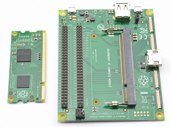
Figure 9-29. The Raspberry Pi Compute module and IO Board
The hardware is based on the original Raspberry Pi, but instead of an SD card slot, there is a 4GB Flash chip built onto the board.
The idea behind this board is that product developers can create their own PCB with a SODIMM socket on it into which the Pi Compute module could be plugged. The companion IO board is just there for you to prototype your designs using the compute board.
Discussion
This board was released before the Raspberry Pi Zero (Recipe 9.22), and at the time of writing seems somewhat redundant as it is more expensive than the Zero, does not perform as well, and is only slightly smaller. It also lacks any of the connectors present on the Pi Zero, which may be just what you need in your product without having to design your own PCB.
A smattering of products have been produced that use the Compute module, but without a hardware refresh and/or big price drop, this board may have an uncertain future.
See Also
For full information on the Pi Compute module, see https://www.raspberrypi.org/blog/raspberry-pi-compute-module-new-product/.
9.22 The Pi Zero
Solution
The small size and extremely low cost of the Pi Zero make it the ideal choice for embedding in electronics projects.
Figure 9-30 shows a Raspberry Pi Zero.
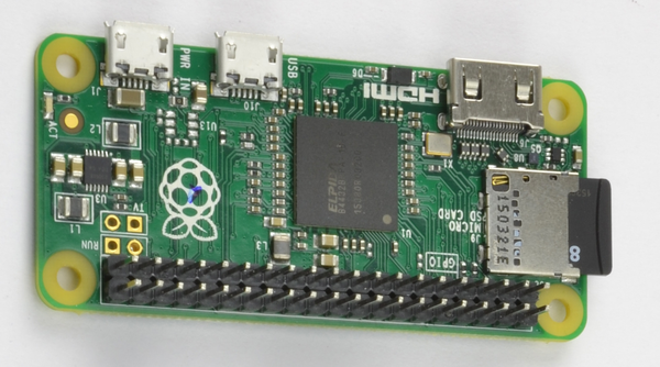
Figure 9-30. The Raspberry Pi Zero
The Pi Zero is supplied without header pins attached, so your first job is likely to be to solder pins to it. Suitable header pins are available in Pi Zero starter kits, such as the one supplied by Pi Hut.
You can also use the easier-to-find single-row header pins, just by soldering two lengths side by side.
Discussion
With only one USB connector—and a micro USB OTG (on the go) connector at that, you will need a USB adapter and USB hub to be able to plug in a USB WiFi dongle, keyboard, and mouse in order to set up the Pi Zero.
Alternatively, you can use a console cable as described in Recipe 2.6 to set up WiFi by editing /etc/network/interfaces as described in Recipe 2.5. Once that is set up, you can connect to the Pi Zero wirelessly using SSH (Recipe 2.7).
See Also
For a comparison of the Raspberry Pi models available, see Recipe 1.1.