Table of Contents for
Raspberry Pi Cookbook, 2nd Edition
 Raspberry Pi Cookbook, 2nd Edition
Published by
O'Reilly Media, Inc., 2016
Raspberry Pi Cookbook, 2nd Edition
Published by
O'Reilly Media, Inc., 2016
- nav
- Cover
- Raspberry Pi Cookbook
- Raspberry Pi Cookbook
- Preface to the Second Edition
- Setup and Management
- Networking
- Operating System
- Software
- Python Basics
- Python Lists and Dictionaries
- Advanced Python
- Computer Vision
- Hardware Basics
- Controlling Hardware
- Motors
- Digital Inputs
- Sensors
- Displays
- The Internet of Things
- Arduino and Raspberry Pi
- Parts and Suppliers
- Raspberry Pi Pinouts
- Index
- About the Author
- Colophon
Chapter 11. Motors
11.1 Controlling Servo Motors
Note
Be sure to check out the accompanying video for this recipe at http://razzpisampler.oreilly.com.
Solution
Use PWM to control the width of pulses to a servo motor to change its angle. Although this will work, the PWM generated is not completely stable, so there will be a little bit of jitter with the servo. For an alternative solution that produces much more stable pulse timing using the ServoBlaster device driver software, see Recipe 11.2.
If you have an older Raspberry Pi 1, you should also power the servo from a separate 5V power supply because peaks in the load current are very likely to crash or overload the Raspberry Pi. If you have a Raspberry Pi B+ or newer, then improvements in the onboard voltage regulation mean that you may get away with powering small servos directly from the 5V pin on the GPIO port.
Figure 11-1 shows a small 9g servo (see “Miscellaneous”) working quite happily with a Raspberry Pi B+.
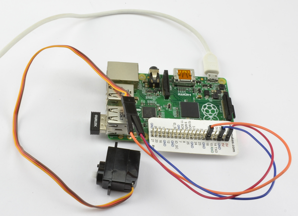
Figure 11-1. Direct connection of a small servo to a Raspberry Pi B+
The leads of the servo are usually 5V wire as red, the ground brown, and the control lead orange. The 5V and ground leads are connected to the GPIO header 5V and GND pins, and the control lead is connected to pin 18. The connections are made with female-to-male header leads.
If you are using a separate power supply, then a breadboard is a good way of keeping all the leads together.
In this case, you will need:
-
5V servo motor (see “Miscellaneous”)
-
Breadboard and jumper wires (see “Prototyping Equipment”)
-
1kΩ resistor (see “Resistors and Capacitors”)
-
5V 1A power supply or 4.8V battery pack (see “Miscellaneous”)
The breadboard layout for this is shown in Figure 11-2.
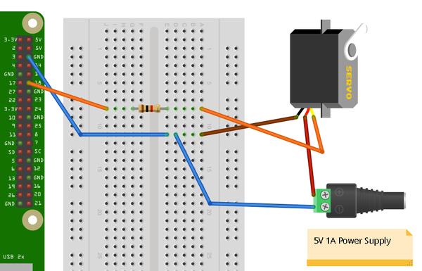
Figure 11-2. Controlling a servo motor
The 1kΩ resistor is not essential, but it does protect the GPIO pin from unexpectedly high currents in the control signal, which could occur if a fault developed on the servo.
You can, if you prefer, power the servo from a battery pack rather than a power supply. Using a four-cell AA battery holder with rechargeable batteries will provide around 4.8V and work well with a servo. Using four alkali AA cells to provide 6V will be fine for many servos, but check the datasheet of your servo to make sure it is OK with 6V.
The user interface for setting the angle of the servo is based on the gui_slider.py program intended for controlling the brightness of an LED (Recipe 10.9). However, you can modify it so that the slider sets the angle to be between 0 and 180 degrees (Figure 11-3).
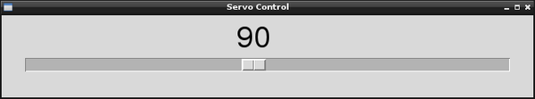
Figure 11-3. User interface for controlling a servo motor
Open an editor (nano or IDLE) and paste in the following code. As with all the program examples in this book, you can also download the program from the Code section of the Raspberry Pi Cookbook website, where it is called servo.py.
Note that this program uses a graphical user interface, so you cannot run it from SSH.
You must run it from the windowing environment on the Pi itself or via remote control using VNC (Recipe 2.8) or RDP (Recipe 2.9). You also need to run it as superuser, so run it with the command sudo python servo.py:
fromTkinterimport*importRPi.GPIOasGPIOimporttimeGPIO.setmode(GPIO.BCM)GPIO.setup(18,GPIO.OUT)pwm=GPIO.PWM(18,100)pwm.start(5)classApp:def__init__(self,master):frame=Frame(master)frame.pack()scale=Scale(frame,from_=0,to=180,orient=HORIZONTAL,command=self.update)scale.grid(row=0)defupdate(self,angle):duty=float(angle)/10.0+2.5pwm.ChangeDutyCycle(duty)root=Tk()root.wm_title('Servo Control')app=App(root)root.geometry("200x50+0+0")root.mainloop()
Discussion
Servo motors are used in remote control vehicles and robotics. Most servo motors are not continuous; that is, they cannot rotate all the way around but rather just over an angle of about 180 degrees.
The position of the servo motor is set by the length of a pulse. The servo expects to receive a pulse at least every 20 milliseconds. If that pulse is high for 1 millisecond, the servo angle will be zero; if it is 1.5 milliseconds, it will be at its center position; and if it is 2 milliseconds, it will be at 180 degrees (Figure 11-4).
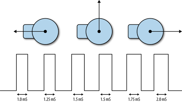
Figure 11-4. Servo motors
The example program sets the PWM frequency to 100 Hz, which will send a pulse to the servo every 10 milliseconds. The angle is converted into a duty cycle between 0 and 100.
See Also
If you have a lot of servos to control, or require greater stability and precision, then you can use a dedicated servo controller module, as described in Recipe 11.3.
Adafruit has developed another method of servo control.
For an alternative solution that produces much more stable pulse timing using the ServoBlaster device driver software, see Recipe 11.2.
11.2 Controlling Servo Motors Precisely
Solution
Install the Servo Blaster device driver.
The Servo Blaster software crated by Richard Hurst uses Raspberry Pi CPU hardware to generate pulses with much more accurate timings than are possible using the RPi.GPIO library. Install this using the following commands and then reboot your Raspberry Pi.
git clone git://github.com/richardghirst/PiBits.git
cd PiBits/ServoBlaster/user
sudo make
sudo make install
The program from Recipe 11.1 can be modified to use the Servo Blaster code. The modified program can be found in the file servo_blaster.py and assumes that the servo control pin is connected to GPIO 18.
fromTkinterimport*importosimporttimeservo_min=500# uSservo_max=2500# uSservo=2# GPIO 18defmap(value,from_low,from_high,to_low,to_high):from_range=from_high-from_lowto_range=to_high-to_lowscale_factor=float(from_range)/float(to_range)returnto_low+(value/scale_factor)defset_angle(angle):pulse=int(map(angle,0,180,servo_min,servo_max))command="echo {}={}us > /dev/servoblaster".format(servo,pulse)os.system(command)classApp:def__init__(self,master):frame=Frame(master)frame.pack()scale=Scale(frame,from_=0,to=180,orient=HORIZONTAL,command=self.update)scale.grid(row=0)defupdate(self,angle):set_angle(float(angle))root=Tk()root.wm_title('Servo Control')app=App(root)root.geometry("200x50+0+0")root.mainloop()
The user interface code is just the same as Recipe 11.1. The differences are in the set_angle function. The set_angle function first uses a utility function called map that converts the angle into a pulse duration using the constants servo_min and servo_max. set_angle. Then it constructs a command that will be run as if from the command line. The format of this line starts with the echo command followed by the servo number to be controlled, then an equals sign, and then a pulse duration in microseconds. This string part of the command will be directed to the device /dev/servoblaster. The servo will then adjust its angle.
Killing ServoBlaster
When ServoBlaster, or more specifically, the service servo.d, is running, you will not be able to use the servo pins for anything and audio on the Raspberry Pi will not work. So when you need to use the pins for something else, use the following commands to disable ServoBlaster and then reboot your Pi.
$ sudo update-rc.d servoblaster disable
$ sudo reboot
When your Raspberry Pi restarts, ServoBlaster will no longer have control of your pins. You can always turn ServoBlaster back on again using:
$ sudo update-rc.d servoblaster enable
$ sudo reboot
Discussion
The ServoBlaster driver is actually very powerful and can be configured to allow you to use pretty much all the GPIO pins to control servos. Its default setup defines eight GPIO pins to act as servo control pins. These are each given a channel number, as shown in Table 11-1.
| Servo Channel | GPIO Pin |
|---|---|
| 0 | 4 |
| 1 | 17 |
| 2 | 18 |
| 3 | 27 |
| 4 | 22 |
| 5 | 23 |
| 6 | 24 |
| 7 | 25 |
Connecting so many servos can result in jumper-lead spaghetti. A board like the MonkMakes Servo Six greatly simplifies the wiring of the servos to your Raspberry Pi.
See Also
You can find the full documentation for Servo Blaster at https://github.com/richardghirst/PiBits/tree/master/ServoBlaster.
If you do not need the precise timing of Servo Blaster, the RPi.GPIO library can also generate pulses for your servo, as described in Recipe 11.1.
11.3 Controlling Many Servo Motors
Solution
Although the Servo Blaster code (see Recipe 11.2) allows you to control lots of servos accurately, it does not solve the problem of wiring up all those servos. You can do this with a breadboard, but it’s messy and wires are quite likely to become loose.
To make connection easy, use a servo motor HAT like the one shown in Figure 11-5.
This HAT allows you to control up to 16 servos or PWM channels using the I2C interface of the Raspberry Pi. The servos just plug straight into the HAT.
Power is supplied to the logic circuits of the module from the 3.3V connection of the Raspberry Pi. This is entirely separate from the power supply for the servo motors, which comes from an external 5V power adapter.
You can, if you prefer, power the servos from a battery pack rather than a power supply. Using a four-cell AA battery holder with rechargeable batteries provides around 4.8V and works well with most servos. Using four alkali AA cells to provide 6V will be fine for many servos, but check the datasheet of your servo to make sure it is OK with 6V.
The pin headers for connecting servos are conveniently arranged so that the servo lead fits directly onto the pins. Be careful to get them facing the right way.
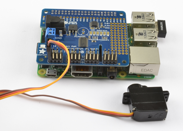
Figure 11-5. Adafruit Servo Motor HAT
To use the Adafruit software for this module, you will need to set up I2C on the Raspberry Pi (Recipe 9.3).
The Adafruit library isn’t really a proper library that contains an installation script, but rather just a directory that contains a number of files. So, when using it, you need to be in the directory to which they are downloaded or your program will not find them.
To download all the Adafruit software libraries for Raspberry Pi, enter the following:
$ git clone https://github.com/adafruit/Adafruit-Raspberry-Pi-Python-Code.git
$ cd Adafruit-Raspberry-Pi-Python-Code
$ cd Adafruit_PWM_Servo_Driver
The last two lines set the current directory to the directory containing the code for PWM as well as an example program supplied by Adafruit, which you can run with the command:
$ sudo python Servo_Example.py
An alternative example next modifies the example program from Recipe 10.2 so that you can use a slider to set the servo position to be between 0 and 180 degrees. The program file must be saved in the Adafruit_PWM_Servo_Driver directory. The slider will change the servo positions of both channels 0 and 1 at the same time, so both servos will follow the position of the slider.
Open an editor (nano or IDLE) and paste in the following code. As with all the program examples in this book, you can also download the program from the Code section of the Raspberry Pi Cookbook website, where it is called servo_module.py. Note that this program uses a graphical user interface, so you can’t run it from SSH. You must run it from the windowing environment on the Pi itself or via remote control using VNC (Recipe 2.8) or RDP (Recipe 2.9).
fromTkinterimport*fromAdafruit_PWM_Servo_DriverimportPWMimporttimepwm=PWM(0x40)pwm.setPWMFreq(50)classApp:def__init__(self,master):frame=Frame(master)frame.pack()scale=Scale(frame,from_=0,to=180,orient=HORIZONTAL,command=self.update)scale.grid(row=0)defupdate(self,angle):pulse_len=int(float(angle)*500.0/180.0)+110pwm.setPWM(0,0,pulse_len)pwm.setPWM(1,0,pulse_len)root=Tk()root.wm_title('Servo Control')app=App(root)root.geometry("200x50+0+0")root.mainloop()
Discussion
The first line after the import creates a new instance of PWM using the I2C address specified as its argument—in this case, 0×40. The module has solder pad connections that allow you to change the I2C address if this conflicts with another I2C device you are using, or you want to use more than one of these modules.
The next line sets the PWM frequency to 50 Hz, which will provide an update pulse every 20 milliseconds.
The line that actually sets the PWM for a particular channel is:
pwm.setPWM(0,0,pulse_len)
The first argument is the PWM channel whose duty cycle is to be changed. Each cycle of PWM is divided into 4,096 ticks, and the second argument is the tick at which the pulse should start. This will always be 0. The third argument is the tick at which the pulse should end. The constants of 500.0 and 110 in the following line were tweaked with a little trial and error to provide a standard servo with as close to 180 degrees of movement as possible:
pulse_len=int(float(angle)*500.0/180.0)+110
When selecting a power supply for this module, remember that a standard remote control servo can easily draw 400mA while it’s moving, and more if it’s under load. So if you plan to have a lot of large servos moving at the same time, you will need a big power adapter.
See Also
A Servo HAT is great if your Raspberry Pi is right by the servo motors, but if your servos are distant from where you want the Raspberry Pi to be, then Adafruit also sells a servo module (product ID 815) that has the same servo controller hardware as the servo HAT, but just has four pins to connect the I2C interface of the board to the Raspberry Pi’s I2C interface.
See the Adafruit documentation for its Raspberry Pi library.
11.4 Controlling the Speed of a DC Motor
Solution
You can use the same design as Recipe 10.5. It is, however, a good idea to place a diode across the motor to prevent voltage spikes from damaging the transistor or even the Raspberry Pi. The 1N4001 is a suitable diode for this. The diode has a stripe at one end, so make sure that this is facing the right way.
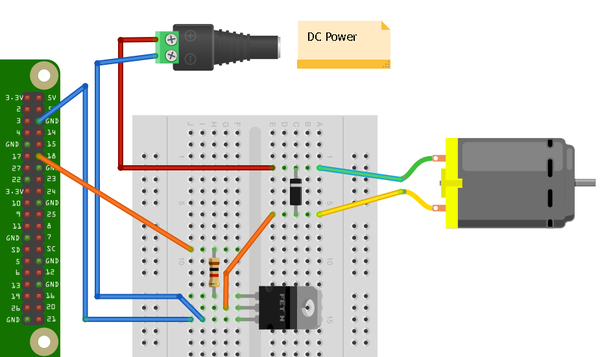
Figure 11-6. Controlling a high-power motor
You will need:
-
3V to 12V DC motor
-
Breadboard and jumper wires (see “Prototyping Equipment”)
-
1kΩ resistor (see “Resistors and Capacitors”)
-
MOSFET Transistor FQP30N06L (see “Transistors and Diodes”)
-
Diode 1N4001 (see “Transistors and Diodes”)
-
Power supply with voltage to match the motor
To control the speed of the motor, you can download the program from the Code section of http://www.raspberrypicookbook.com, where it is called gui_slider.py. Note that this program uses a graphical user interface, so you can’t run it from SSH. You must run it from the windowing environment on the Pi itself or via remote control using VNC (Recipe 2.8) or RDP (Recipe 2.9).
Discussion
If you are only using a low-power DC motor (less than 200mA), you can use a smaller (and cheaper) transistor such as the 2N3904 (see “Transistors and Diodes”). The breadboard layout to use a 2N3904 is shown in Figure 11-7.
You can probably get away with powering a small motor from the 5V supply line on the GPIO connector. If you find that the Raspberry Pi crashes, use an external power supply, as shown in Figure 11-6.
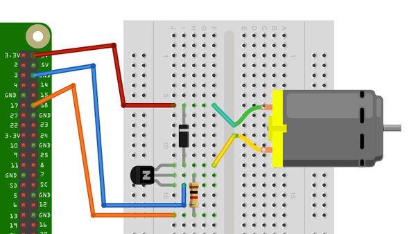
Figure 11-7. Controlling a low-power motor
See Also
This design only controls the motor’s speed. It can’t control its direction. For that, you need to see Recipe 11.5.
For more information on using a breadboard and jumper wires with the Raspberry Pi, see Recipe 9.8.
11.5 Controlling the Direction of a DC Motor
Solution
Use an H-Bridge chip or module.
You have two recipes to choose from for controlling a motor. The first, the “DIY approach,” uses a solderless breadboard and a L293D chip. The second design uses a ready-made H-Bridge module from SparkFun, connecting it directly to the Raspberry Pi with jumper leads.
Both the L293D and the SparkFun module are capable of driving two motors without any extra hardware. The Discussion also mentions a few other options for controlling DC motors.
Option 1: L293D chip and breadboard
If you take the L293D route, you will need:
-
3V to 12V DC motor
-
Breadboard and jumper wires (male to female; see “Prototyping Equipment”)
-
L293D chip (see “Integrated Circuits”)
-
Power supply with voltage to match the motor
The breadboard layout is shown in Figure 11-8.
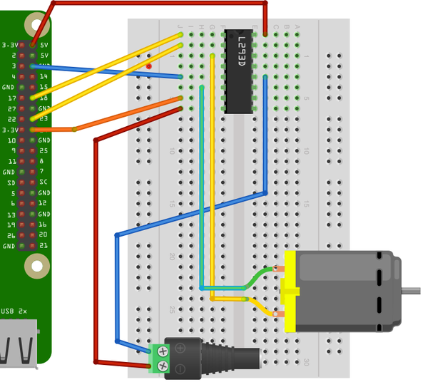
Figure 11-8. Using a L293D chip to control a motor
Make sure the chip is facing the right way: there is a notch in its top, which is the end that should be at the top of the breadboard.
Option 2: Motor controller module
If you decide to use the SparkFun motor controller, or a similar motor controller module, you will need the following:
-
3V to 12V DC motor
-
Jumper wires (female to female; see “Prototyping Equipment”)
-
Header pins (see “Integrated Circuits”)
-
SparkFun motor driver 1A dual (see “Modules”)
-
Power supply with voltage to match the motor
The layout is shown in Figure 11-9. Note that the motor shown is just a DC motor on its own. If the project is driving wheels, then you will typically use a gearmotor, which combines a motor and gearbox to reduce the RPM and increase the torque.
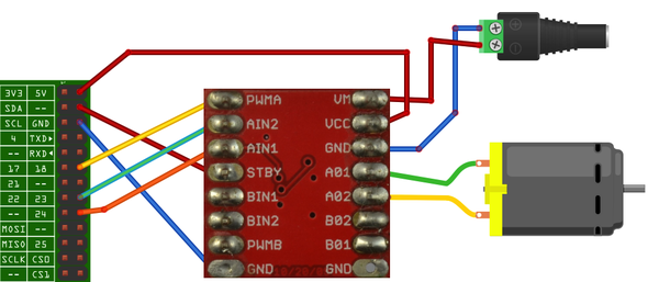
Figure 11-9. Wiring a SparkFun motor controller
The motor controller module comes without header pins attached, so you will need to add these to the board before you get started. The connections are made using female-to-female header leads.
Figure 11-10 shows the module wired up to a small DC gearmotor, as per the wiring diagram of Figure 11-9.
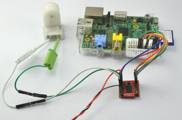
Figure 11-10. Using a SparkFun motor controller with a gearmotor
Software
Whichever hardware option you decided upon, you can use the same program to try out the motor. This allows you to enter a letter f or r and then a single digit between 0 and 9. The motor will then either go forward or backward, at a speed specified by the digit—0 for stopped, 9 for full speed.
$ sudo python motor_control.py
Command, f/r 0..9, E.g. f5 :f5
Command, f/r 0..9, E.g. f5 :f1
Command, f/r 0..9, E.g. f5 :f2
Command, f/r 0..9, E.g. f5 :r2
Open an editor (nano or IDLE) and paste in the following code. As with all the program examples in this book, you can also download the program from the Code section of the Raspberry Pi Cookbook website, where it is called motor_control.py. This program uses the command line, so you can run it from SSH.
If you’re using Python 3, change the command raw_input to just input:
importRPi.GPIOasGPIOimporttimeenable_pin=18in1_pin=23in2_pin=24GPIO.setmode(GPIO.BCM)GPIO.setup(enable_pin,GPIO.OUT)GPIO.setup(in1_pin,GPIO.OUT)GPIO.setup(in2_pin,GPIO.OUT)pwm=GPIO.PWM(enable_pin,500)pwm.start(0)defclockwise():GPIO.output(in1_pin,True)GPIO.output(in2_pin,False)defcounter_clockwise():GPIO.output(in1_pin,False)GPIO.output(in2_pin,True)whileTrue:cmd=raw_input("Command, f/r 0..9, E.g. f5 :")direction=cmd[0]ifdirection=="f":clockwise()else:counter_clockwise()speed=int(cmd[1])*10pwm.ChangeDutyCycle(speed)
Discussion
Before you look at how the program operates, you need to understand a little more about how an H-Bridge works.
Figure 11-11 shows how one works, using switches rather than transistors or a chip. By reversing the polarity across the motor, an H-Bridge also reverses the direction the motor turns.
In Figure 11-11, S1 and S4 are closed and S2 and S3 are open. This allows current to flow through the motor, with terminal A being positive and terminal B being negative. If we were to reverse the switches so that S2 and S3 are closed and S1 and S4 are open, then B would be positive and A would be negative, and the motor would turn in the opposite direction.
However, you may have spotted a danger with this circuit. If by some chance S1 and S2 are both closed, then the positive supply will be directly connected to the negative supply and you will have a short-circuit. The same is true if S3 and S4 are both closed at the same time.
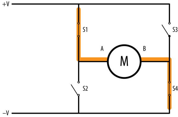
Figure 11-11. An H-Bridge
Although you can use individual transistors to make an H-Bridge, it is simpler to use an H-Bridge IC such as the L293D. This chip actually has two H-Bridges in it, so you can use it to control two motors.
The L293 has three control pins for each of the two motor control channels. The Enable pin just enables or disables the channel as a whole. In the example program, this is connected to a PWM output to control the speed of the motor. The other two pins (IN1 and IN2) control the direction in which the motor will be driven. You can see the use of these two control pins in the functions clockwise and counter_clockwise:
defclockwise():GPIO.output(in1_pin,True)GPIO.output(in2_pin,False)defcounter_clockwise():GPIO.output(in1_pin,False)GPIO.output(in2_pin,True)
If IN1 is high and IN2 is low, the motor will turn in one direction. If those two pins are reversed, the motor will turn in the opposite direction.
As an alternative to using an L293D on a breadboard, very low-cost modules are available from eBay that include a L293D on a PCB with screw terminals to attach motors and header pins to link directly to the Raspberry Pi GPIO connector. If you need a higher-power motor controller module, then you can find motor controller modules that operate on the same principles but at much higher currents, even up to 20A or more. Polulu has an impressive range of such motor controller boards.
See Also
The Adafruit Stepper Motor HAT (Recipe 11.8) and RaspiRobot board (Recipe 11.9) can also be used to control the speed and direction of a DC motor.
Check out the L293D datasheet and the SparkFun Motor Driver Module product page.
For more information on using a breadboard and jumper wires with the Raspberry Pi, see Recipe 9.8.
11.6 Using a Unipolar Stepper Motor
Solution
Use a ULN2803 Darlington driver chip on breadboard.
Stepper motors fit somewhere between DC motors and servo motors in the world of motor technologies. Like a regular DC motor, they can rotate continuously, but you can also very accurately position them by moving them a step at a time in either direction.
To make this recipe, you will need:
-
5V, five-pin unipolar stepper motor (see “Miscellaneous”)
-
ULN2803 Darlington driver IC (see “Integrated Circuits”)
-
Breadboard and jumper wires (see “Prototyping Equipment”)
Figure 11-12 shows the wiring diagram for using a ULN2803. Note that the chip can be used to drive two such motors. To drive a second stepper motor, you will need to connect four more control pins from the GPIO connector to pins 5 to 8 of the ULN2803, and connect the second motor’s four pins to pins 11 to 14 of the ULN2803.
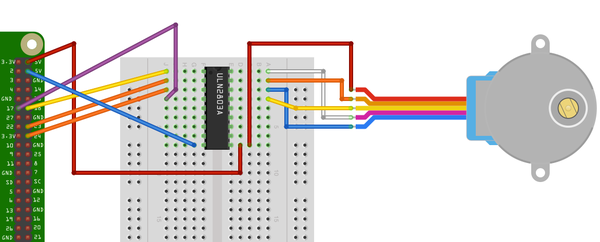
Figure 11-12. Using a ULN2803 to control a unipolar stepper motor
The 5V supply from the GPIO connector may work OK with a small stepper motor. If you experience problems with the Raspberry Pi crashing or need to use a bigger stepper motor, then use a separate supply for the power to the motor (pin 10 of the ULN2803).
Open an editor (nano or IDLE) and paste in the following code. As with all the program examples in this book, you can also download the program from the Code section of the Raspberry Pi Cookbook website, where it is called stepper.py. This program uses the command line, so you can run it from SSH.
If you’re using Python 3, change the command raw_input to just input:
importRPi.GPIOasGPIOimporttimeGPIO.setmode(GPIO.BCM)coil_A_1_pin=18coil_A_2_pin=23coil_B_1_pin=24coil_B_2_pin=17GPIO.setup(coil_A_1_pin,GPIO.OUT)GPIO.setup(coil_A_2_pin,GPIO.OUT)GPIO.setup(coil_B_1_pin,GPIO.OUT)GPIO.setup(coil_B_2_pin,GPIO.OUT)forward_seq=['1010','0110','0101','1001']reverse_seq=list(forward_seq)# to copy the listreverse_seq.reverse()defforward(delay,steps):foriinrange(steps):forstepinforward_seq:set_step(step)time.sleep(delay)defbackwards(delay,steps):foriinrange(steps):forstepinreverse_seq:set_step(step)time.sleep(delay)defset_step(step):GPIO.output(coil_A_1_pin,step[0]=='1')GPIO.output(coil_A_2_pin,step[1]=='1')GPIO.output(coil_B_1_pin,step[2]=='1')GPIO.output(coil_B_2_pin,step[3]=='1')whileTrue:set_step('0000')delay=raw_input("Delay between steps (milliseconds)?")steps=raw_input("How many steps forward? ")forward(int(delay)/1000.0,int(steps))set_step('0000')steps=raw_input("How many steps backwards? ")backwards(int(delay)/1000.0,int(steps))
When you run the program, you will be prompted for a delay between steps. This should be 2 or more. You will then be prompted for the number of steps in each direction:
$ sudo python stepper.py
Delay between steps (milliseconds)?2
How many steps forward? 100
How many steps backwards? 100
Delay between steps (milliseconds)?10
How many steps forward? 50
How many steps backwards? 50
Delay between steps (milliseconds)?
Discussion
Stepper motors use a cogged rotor and electromagnets to nudge the wheel around a step at a time (Figure 11-13). Note that the colors of the leads will vary.
Energizing the coils in a certain order drives the motor around. The number of steps that the stepper motor has in a 360-degree rotation is actually the number of teeth on the rotor.
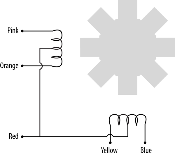
Figure 11-13. A stepper motor
The example program uses a list of strings to represent each of the four energization stages that make up a single step:
forward_seq=['1010','0110','0101','1001']
The sequence for rotating the motor in the opposite direction is just the reverse of the sequence for moving forward.
You can use the forward and backward functions in your programs to step the motor back and forth. The first argument to either function is the delay in milliseconds between each part of the step sequence. This minimum value for this depends on the motor you use. If it’s too small, the motor will not turn. Typically, two milliseconds or more will be fine. The second parameter is the number of steps to take.
defforward(delay,steps):foriinrange(steps):forstepinforward_seq:set_step(step)time.sleep(delay)
The forward function has two nested for loops. The outer one repeats for the number of steps and the inner one iterates over the sequence of motor activations, calling setStep for each in sequence.
defset_step(step):GPIO.output(coil_A_1_pin,step[0]=='1')GPIO.output(coil_A_2_pin,step[1]=='1')GPIO.output(coil_B_1_pin,step[2]=='1')GPIO.output(coil_B_2_pin,step[3]=='1')
The set_step function sets each of the control pins to high or low, depending on the pattern supplied as its argument.
The main loop sets the step to 0000 between moving forward and backward, to set the outputs all to zero when the motor is not actually turning. Otherwise, one of the coils may be left on, causing the motor to draw current unnecessarily.
See Also
If you have a four-wire bipolar stepper motor, see Recipe 11.7.
For more information on stepper motors, the different types, and how they work, see Wikipedia, where you will also find a nice animated explanation of the activation pattern for driving the motor.
For information on using servo motors, see Recipe 11.1; for controlling DC motors, see Recipes 7.16 and 7.18.
For more information on using a breadboard and jumper wires with the Raspberry Pi, see Recipe 9.8.
11.7 Using a Bipolar Stepper Motor
Solution
Use a L293D H-Bridge driver chip. An H-Bridge is required to drive a bipolar stepper motor because, as the word bipolar suggests, the direction of current across the windings needs to be reversed, rather like driving a DC motor in both directions (see Recipe 11.5).
To make this recipe, you will need:
-
12V, four-pin bipolar stepper motor (see “Miscellaneous”)
-
L293D H-Bridge IC (see “Integrated Circuits”)
-
Breadboard and jumper wires (see “Prototyping Equipment”)
The motor used here, a 12V, is somewhat larger than the previous unipolar stepper motor example. The power for the motor itself is therefore supplied from an external power supply rather than from the Raspberry Pi. See the wiring diagram in Figure 11-14.
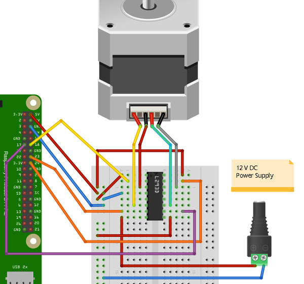
Figure 11-14. Using a L293D to control a bipolar stepper motor
Discussion
You can use the exact same stepper.py program to control this stepper (see Recipe 11.6). The design uses both H-Bridges of the L293D, so you need one of these chips for each motor you want to control.
See Also
If the type of stepper motor you have is a five-wire unipolar stepper motor, see Recipe 11.6.
For more information on stepper motors—the different types and how they work—see Wikipedia, where you will also find a nice animated explanation of the activation pattern for driving the motor.
For information on using servo motors, see Recipe 11.1 and for controlling DC motors, see Recipes 7.16 and 7.18.
For more information on using a breadboard and jumper wires with the Raspberry Pi, see Recipe 9.8.
You can also drive a stepper motor by using the RasPiRobot board (Recipe 11.9).
11.8 Using a Stepper Motor HAT to Drive a Bipolar Stepper Motor
Solution
Use an Adafruit Stepper Motor HAT (Figure 11-15).
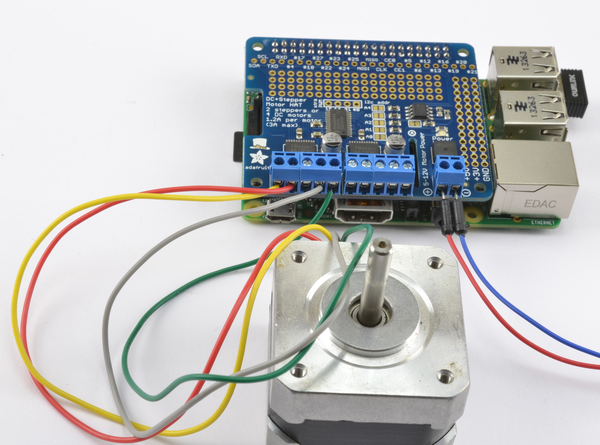
Figure 11-15. Using an Adafruit stepper motor HAT to control a bipolar stepper motor
This board is capable of driving two bipolar stepper motors. Figure 11-15 shows the board with one bipolar stepper motor with one coil connected to the M1 terminals and the other coil to the M2 terminals. The power for the motors is supplied separately at the screw terminals on the right of Figure 11-15.
This HAT uses I2C so make sure that you have I2C enabled (Recipe 9.3).
To make it easy to use the HAT, Adafruit has written a Python library. To install it, enter the following commands:
$ git clone https://github.com/adafruit/Adafruit-Motor-HAT-Python-Library.git
$ sudo apt-get install python-dev
$ cd Adafruit-Motor-HAT-Python-Library/
$ sudo python setup.py install
The library includes a few examples, so change directory and then run the basic example using the commands:
$ cd examples
$ sudo python StepperTest.py
I2C Busses
If you followed recipe Recipe 9.20 to make your own HAT and enabled the I2C bus 0 as described there, then you will need to reverse the change to /boot/config.txt because the Adafruit autodetects the I2C bus to use and will detect the wrong one if bus 0 is enabled.
In /boot/config.txt, delete or uncomment out the line:
dtparam=i2c_vc=on
Once this is done, reboot your Raspberry Pi.
Discussion
When you run the program, the motor will start to turn and the program will loop round four different modes of stepping. You might like to try the simple example below to control your stepper motor.
Open an editor (nano or IDLE) and paste in the following code. As with all the program examples in this book, you can also download the program from the Code section of the Raspberry Pi Cookbook website, where it is called stepper_hat.py. This program uses the command line, so you can run it from SSH.
fromAdafruit_MotorHATimportAdafruit_MotorHATimporttimeHAT=Adafruit_MotorHATstepper_hat=Adafruit_MotorHAT()stepper=stepper_hat.getStepper(200,1)# 200 steps/rev, port 1 (M1, M2)try:whileTrue:speed=input("Enter stepper speed (rpm) ")stepper.setSpeed(speed)steps_forward=input("Steps forward ")stepper.step(steps_forward,HAT.FORWARD,HAT.SINGLE)steps_forward=input("Steps reverse ")stepper.step(steps_forward,HAT.BACKWARD,HAT.SINGLE)finally:("cleaning up")stepper_hat.getMotor(1).run(HAT.RELEASE)
After importing the Adafruit_MotorHAT module, it is assigned the name HAT just to reduce the verbosity of the code on the lines that follow this.
The try/finally block is used to make sure that the power to the coils are released when the program is stopped using Ctrl-C.
See Also
For a discussion of the HAT standard and how to make your own HAT, see Recipe 9.20.
For more information on using this HAT and its accompanying library, see https://learn.adafruit.com/adafruit-dc-and-stepper-motor-hat-for-raspberry-pi/.
To use a L293D to control a stepper motor, see Recipe 11.7; and for a RaspiRobot board, see Recipe 11.9.
11.9 Using a RaspiRobot Board to Drive a Bipolar Stepper Motor
Note
Be sure to check out the accompanying video for this recipe at http://razzpisampler.oreilly.com.
Solution
Use a RaspiRobot board Version 3.
The RaspiRobot board uses the power supply directly from its screw terminals as the supply to the motor and regulates that same supply down to 5V to drive the Raspberry Pi. So in this case, the 12V power will be supplying both the 12V stepper motor and the Raspberry Pi.
Warning
If you are using an earlier version of the RasPiRobot board (version 1 or 2), then do not power the Raspberry Pi through its USB connection at the same time as you power it through the RasPiRobot board.
There is no problem powering it through both in version 3 of the board.
Connect the stepper motor and power supply to the RaspiRobot board as shown in Figure 11-16. The wire colors for the Adafruit 12V stepper motor are, in order from left to right: yellow, red, gray, and green.
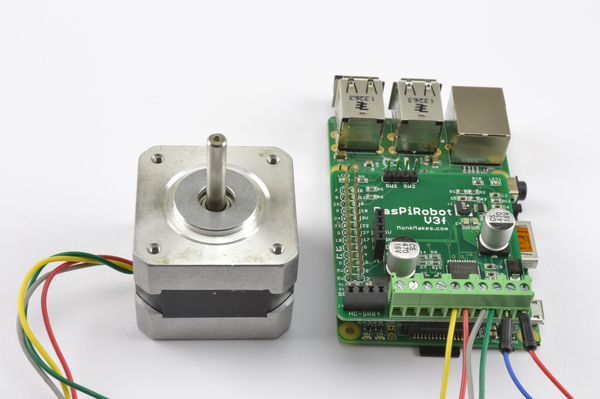
Figure 11-16. Using a RaspiRobot board to control a bipolar stepper motor
Before you can run the program, you will need to install the library for the RaspiRobot V3 using the following commands:
$ git clone https://github.com/simonmonk/raspirobotboard3.git
$ cd raspirobotboard3/python
$ sudo python setup.py install
Open an editor (nano or IDLE) and paste in the following code. As with all the program examples in this book, you can also download the program from the Code section of the Raspberry Pi Cookbook website, where it is called stepper_rrb.py. This program uses the command line, so you can run it from SSH.
If you’re using Python 3, change the command raw_input to just input:
fromrrb3import*importtimerr=RRB3(12.0,12.0)# battery, motortry:whileTrue:delay=raw_input("Delay between steps (milliseconds)?")steps=raw_input("How many steps forward? ")rr.step_forward(int(delay)/1000.0,int(steps))steps=raw_input("How many steps backwards? ")rr.step_reverse(int(delay)/1000.0,int(steps))finally:GPIO.cleanup()
Discussion
You will find that there is a minimum value of "Delay between steps", below which the motor will just judder rather than turn.
See Also
You can find full documentation for the RaspiRobot board and other projects that use it at the RaspiRobot website.
To drive a stepper motor using a L293D on a breadboard, see Recipe 11.7.
11.10 Building a Simple Robot Rover
Solution
Use a RaspiRobot board V3 as an interface board to the Raspberry Pi to control two motors and a robot chassis kit such as the Magician Chassis.
To make this recipe, you will need:
-
RaspiRobot board V3 (see “Modules”)
-
Gearmotor chassis such as the Magician Chassis (see “Miscellaneous”)
-
6×AA battery holder (see “Miscellaneous”)
-
USB WiFi adapter
You can also buy a complete kit of parts for building this rover as the MonkMakes RaspiRobot Rover Kit.
The first step in building the robot is to assemble the chassis. Most low-cost gearmotor chassis are supplied with a four-cell AA battery holder, but to provide power to the Raspberry Pi, you really need a six-cell battery holder. When you get to that part of the instructions supplied with the chassis, use a 6×AA battery box.
Follow the wiring instructions as shown in Figure 11-17.
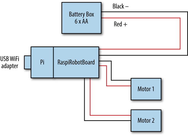
Figure 11-17. Wiring a roving robot
The battery pack will supply power to the RaspiRobot board, which in turn supplies 5V to the Raspberry Pi. So only one power supply is required.
The finished rover should look something like Figure 11-18, which also has a rangefinder on the front for good measure.
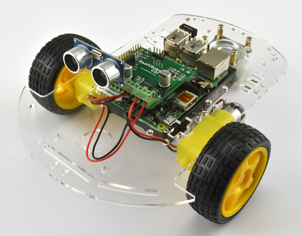
Figure 11-18. The finished robot
To drive the robot, you are going to use a control program that allows you to steer the rover using keys on a laptop or other computer connected to your Raspberry Pi over SSH. If you have not already done so, set up your Raspberry Pi to use WiFi and SSH, using Recipe 2.5 and Recipe 2.7.
Open an editor (nano or IDLE) and paste in the following code. As with all the program examples in this book, you can also download the program from the Code section of the Raspberry Pi Cookbook website, where it is called rover.py.
fromrrb3import*importsysimportttyimporttermiosrr=RRB3(9.0,6.0)# battery, motorUP=0DOWN=1RIGHT=2LEFT=3("Use the arrow keys to move the robot")("Press Ctrl-C to quit the program")# These functions allow the program to read your keyboarddefreadchar():fd=sys.stdin.fileno()old_settings=termios.tcgetattr(fd)try:tty.setraw(sys.stdin.fileno())ch=sys.stdin.read(1)finally:termios.tcsetattr(fd,termios.TCSADRAIN,old_settings)ifch=='0x03':raiseKeyboardInterruptreturnchdefreadkey(getchar_fn=None):getchar=getchar_fnorreadcharc1=getchar()iford(c1)!=0x1b:returnc1c2=getchar()iford(c2)!=0x5b:returnc1c3=getchar()returnord(c3)-65# 0=Up, 1=Down, 2=Right, 3=Left arrows# This will control the movement of your robot and display on your screentry:whileTrue:keyp=readkey()ifkeyp==UP:rr.forward(1)'forward'elifkeyp==DOWN:rr.reverse(1)'backward'elifkeyp==RIGHT:rr.right(1)'clockwise'elifkeyp==LEFT:rr.left(1)'anti clockwise'elifkeyp==LEFT:rr.left(1)'anti clockwise'eliford(keyp)==3:breakexceptKeyboardInterrupt:GPIO.cleanup()
To be able to intercept keypresses, this program uses the termios library and the two functions readchar and readkey.
After the import commands, a new instance of RRB3 is created. The two parameters to this are the battery voltage and the motor voltage (in this case, 9V and 6V respectively). If your chassis has different voltage motors, then change the second parameter.
The main loop just checks for keypresses and then sends the appropriate commands of forward, reverse, left, or right to the RRB3 library.
Discussion
You can make the rover more interesting by adding peripherals to it. You could, for example, attach a webcam and set up web streaming so that your roving robot becomes a roving spycam (Recipe 4.5).
The RRB3 library also supports the HC-SR04 rangefinders that can be plugged into a socket on the RaspiRobot board V3. You can use this to detect obstacles, and you will find example software for this in the RRB3 library.
See Also
You can find out more about the RaspiRobot board and the RRB3 library on GitHub.