Table of Contents for
Raspberry Pi Cookbook, 2nd Edition
 Raspberry Pi Cookbook, 2nd Edition
Published by
O'Reilly Media, Inc., 2016
Raspberry Pi Cookbook, 2nd Edition
Published by
O'Reilly Media, Inc., 2016
- nav
- Cover
- Raspberry Pi Cookbook
- Raspberry Pi Cookbook
- Preface to the Second Edition
- Setup and Management
- Networking
- Operating System
- Software
- Python Basics
- Python Lists and Dictionaries
- Advanced Python
- Computer Vision
- Hardware Basics
- Controlling Hardware
- Motors
- Digital Inputs
- Sensors
- Displays
- The Internet of Things
- Arduino and Raspberry Pi
- Parts and Suppliers
- Raspberry Pi Pinouts
- Index
- About the Author
- Colophon
Chapter 12. Digital Inputs
12.0 Introduction
In this chapter, you look at recipes for using digital inputs, such as switches and keypads. This chapter also covers modules that have a digital output that can be connected to a Raspberry Pi GPIO input.
Most of the recipes require the use of a solderless breadboard and jumper wires (see Recipe 9.8).
12.1 Connecting a Push Switch
Note
Be sure to check out the accompanying video for this recipe at http://razzpisampler.oreilly.com.
Solution
Connect a switch to a GPIO pin and use the RPi.GPIO library in your Python program to detect the button press.
To make this recipe, you will need:
-
Breadboard and jumper wires (see “Prototyping Equipment”)
-
Tactile push switch (see “Miscellaneous”)
Figure 12-1 shows how to connect a tactile push switch using a breadboard and jumper wires.
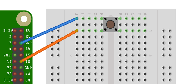
Figure 12-1. Connecting a push switch to a Raspberry Pi
An alternative to using a breadboard and tactile switch is to use a Squid Button (Figure 12-2). This is a push switch with female header leads soldered to the end, which can be connected directly to a the GPIO connector (Recipe 9.11).

Figure 12-2. A Squid Button
Open an editor (nano or IDLE) and paste in the following code. As with all the program examples in this book, you can also download the program from the Code section of the Raspberry Pi Cookbook website, where it is called switch.py.
This example code displays a message when the button is pressed:
importRPi.GPIOasGPIOimporttimeGPIO.setmode(GPIO.BCM)GPIO.setup(18,GPIO.IN,pull_up_down=GPIO.PUD_UP)whileTrue:input_state=GPIO.input(18)ifinput_state==False:('Button Pressed')time.sleep(0.2)
You will need to run the program as superuser:
pi@raspberrypi ~ $ sudo python switch.py
Button Pressed
Button Pressed
Button Pressed
Button Pressed
Discussion
You will notice that the switch is wired so that when it is pressed, it will connect pin 18 configured as an input to GND. The input pin is normally pulled up to 3.3V by the optional argument pull_up_down=GPIO.PUD_UP in GPIO.setup. This means that when you read the input value using GPIO.input, False will be returned if the button is pressed. This is a little counterintuitive.
Each GPIO pin has software-configurable pull-up and pull-down resistors. When using a GPIO pin as an input, you can configure these resistors so that one, either, or neither of the resistors is enabled, using the optional pull_up_down parameter to GPIO.setup. If this parameter is omitted, then neither resistor will be enabled. This leaves the input floating, which means that its value cannot be relied upon and it will drift between high and low depending on what it picks up in the way of electrical noise.
If it is set to GPIO.PUD_UP, the pull-up resistor is enabled; if it is set to GPIO.PUD_DOWN, the pull-down resistor is enabled.
You might expect the push switch to have just two connections, which are either open or closed. While some of these tactile push switches do have just two connections, most have four. Figure 12-3 shows how these connections are arranged.
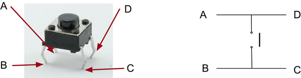
Figure 12-3. A tactile push switch
Actually, there are really only two electrical connections because inside the switch package, pins B and C are connected together, as are A and D.
See Also
For more information on using a breadboard and jumper wires with the Raspberry Pi, see Recipe 9.8.
To use a switch to trigger an interrupt, see Recipe 10.13.
To debounce a switch, see Recipe 12.5.
To use external pull-up or pull-down resistors, see Recipe 12.6.
12.2 Toggling with a Push Switch
Solution
Record the last state of the button and invert that value each time the button is pressed.
The following example toggles an LED on and off as you press the switch.
To make this recipe, you will need:
-
Breadboard and jumper wires (see “Prototyping Equipment”)
-
Tactile push switch (see “Miscellaneous”)
-
LED (see “Opto-Electronics”)
-
470Ω resistor (see “Resistors and Capacitors”)
Figure 12-4 shows how to connect a tactile push switch and LED, using a breadboard and jumper wires.
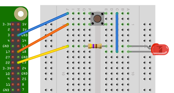
Figure 12-4. Connecting a push switch and LED to a Raspberry Pi
In addition to the male-to-female jumper wires connecting the Raspberry Pi to the breadboard, you will also need one male-to-male jumper wire or solid core wire.
Open an editor (nano or IDLE) and paste in the following code. As with all the program examples in this book, you can also download the program from the Code section of the Raspberry Pi Cookbook website, where it’s called switch_on_off.py:
importRPi.GPIOasGPIOimporttimeGPIO.setmode(GPIO.BCM)switch_pin=18led_pin=23GPIO.setup(switch_pin,GPIO.IN,pull_up_down=GPIO.PUD_UP)GPIO.setup(led_pin,GPIO.OUT)led_state=Falseold_input_state=True# pulled-upwhileTrue:new_input_state=GPIO.input(switch_pin)ifnew_input_state==Falseandold_input_state==True:led_state=notled_stateold_input_state=new_input_stateGPIO.output(led_pin,led_state)
Discussion
The variable led_state contains the current state of the LED (True for on and False for off). Whenever the button is pressed, the following line is run:
led_state=notled_state
The not command inverts the value of led_state, so if led_state is True, it becomes False and vice versa.
The variable old_input_state is used to remember the button position so that a button press is defined as occurring only when the input state changes from being True (switch not pressed) to False (switch pressed).
See Also
You will find that sometimes when you press the button, it does not seem to toggle the LED. This is because of switch bounce. You can find other techniques for avoiding switch bounce in Recipe 12.5.
12.3 Using a Two-Position Toggle or Slide Switch
Solution
Use the switch as you would a tactile push switch (Recipe 12.1): just connect the center and one end contact (Figure 12-5).
To make this recipe, you will need:
-
Breadboard and jumper wires (see “Prototyping Equipment”)
-
Miniature toggle or slide switch (see “Miscellaneous”)
The same code you used in Recipe 12.1 works with this arrangement.
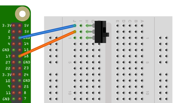
Figure 12-5. Connecting a slide switch to a Raspberry Pi
Discussion
These type of slide switches are useful because you can see the position they are set to without the need for some additional indicator like an LED. However, they are more fragile and a little more expensive than the tactile push switches that are used more and more in consumer electronics because they can sit behind a nicer-looking plastic button.
See Also
To use a three-position switch, with a center-off position, see Recipe 12.4.
12.4 Using a Center-Off Toggle or Slide Switch
Solution
Connect the switch to two GPIO pins, as shown in Figure 12-6, and use the RPi.GPIO library in your Python program to detect the position of the switch.
To make this recipe, you will need:
-
Breadboard and jumper wires (see “Prototyping Equipment”)
-
Miniature center-off three-position toggle switch (see “Miscellaneous”)
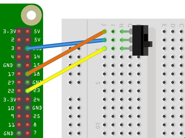
Figure 12-6. Connecting a three-position switch to a Raspberry Pi
The common (center) connection of the switch is connected to ground, and each of the two ends of the switch are connected to a GPIO pin with the internal pull-up resistor enabled.
Open an editor (nano or IDLE) and paste in the following code. As with all the program examples in this book, you can also download the program from the Code section of the Raspberry Pi Cookbook website, where it is called switch_2_pos.py:
importRPi.GPIOasGPIOimporttimeGPIO.setmode(GPIO.BCM)top_input=18bottom_input=23GPIO.setup(top_input,GPIO.IN,pull_up_down=GPIO.PUD_UP)GPIO.setup(bottom_input,GPIO.IN,pull_up_down=GPIO.PUD_UP)switch_position="unknown"whileTrue:top_state=GPIO.input(top_input)bottom_state=GPIO.input(bottom_input)new_switch_position="unknown"iftop_state==False:new_switch_position="up"elifbottom_state==False:new_switch_position="down"else:new_switch_position="center"ifnew_switch_position!=switch_position:switch_position=new_switch_position(switch_position)
Run the program, and as you move the switch from top to center to bottom, the position of the switch will be reported every time it changes:
$ sudo python switch_3_pos.py
up
center
down
Discussion
The program sets up two inputs with pull-up resistors enabled. The variable switch_position is used to record the current position of the switch.
Inside the loop, both GPIO inputs are read and the three conditions of the if, elif, and else structure determine the position of the switch, assigning the value to a variable called new_switch_position. If this differs from the previous value, then the switch position is printed.
You will find a wide range of types of toggle switches. Some will be described as DPDT, SPDT, SPST, or SPST, momentary on, and so on. The meaning of these letters is as follows:
-
D: Double
-
S: Single
-
P: Pole
-
T: Throw
A DPDT switch is double pole, double throw. The word pole refers to the number of separate switch contacts that are controlled from the one mechanical lever. So, a double pole switch can switch two things on and off independently. A single throw switch can only open or close a single contact (or two contacts if it is double pole). However, a double throw switch can connect the common contact to one of two other contacts.
Figure 12-7 shows the most common types of switch.
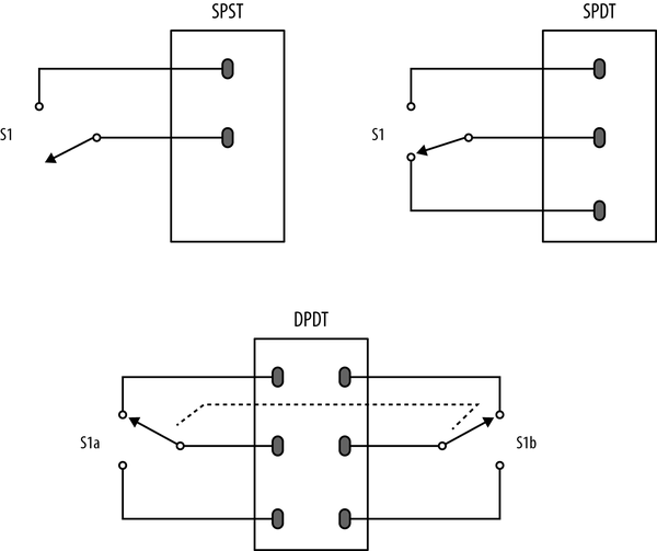
Figure 12-7. Types of toggle switches
See Also
For more information on how if statements work, see Recipe 5.18. For the most basic switch recipe, see Recipe 12.1.
12.5 Debouncing a Button Press
Solution
There are a number of solutions to this problem. To explore them, build the breadboard setup from Recipe 12.2.
The original code for this example, without any attempt at debouncing, looks like this:
importRPi.GPIOasGPIOimporttimeGPIO.setmode(GPIO.BCM)switch_pin=18led_pin=23GPIO.setup(switch_pin,GPIO.IN,pull_up_down=GPIO.PUD_UP)GPIO.setup(led_pin,GPIO.OUT)led_state=Falseold_input_state=True# pulled-upwhileTrue:new_input_state=GPIO.input(switch_pin)ifnew_input_state==Falseandold_input_state==True:led_state=notled_stateold_input_state=new_input_stateGPIO.output(led_pin,led_state)
The problem is that if the switch contacts bounce, it is just as if the switch were pressed more than once in very rapid succession. If they bounce an odd number of times, then things will seem to be OK. But if they bounce an even number of times, the two events will toggle the LED on and then straight back off again.
You need to ignore any changes after the switch is pressed for a short amount of time, while the switch finishes bouncing.
The quick and easy way to do this is to introduce a short sleep after the button press is detected by adding a time.sleep command of, say, 0.2 seconds. This delay is probably much higher than necessary, strictly speaking. You may find that you can reduce this considerably.
importRPi.GPIOasGPIOimporttimeGPIO.setmode(GPIO.BCM)switch_pin=18led_pin=23GPIO.setup(switch_pin,GPIO.IN,pull_up_down=GPIO.PUD_UP)GPIO.setup(led_pin,GPIO.OUT)led_state=Falseold_input_state=True# pulled-upwhileTrue:new_input_state=GPIO.input(switch_pin)ifnew_input_state==Falseandold_input_state==True:led_state=notled_statetime.sleep(0.2)old_input_state=new_input_stateGPIO.output(led_pin,led_state)
Discussion
This solution is OK in most situations, but you might also consider using the switch pin with an interrupt (Recipe 10.13).
Switch bouncing occurs on most switches and can be quite severe on some switches, as the oscilloscope trace in Figure 12-8 shows.
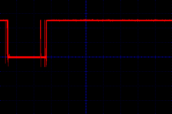
Figure 12-8. Contact bounce with a poor switch
You can see that there is contact bounce both as the switch closes and when it is released. Most switches are not as bad as this one.
See Also
For the basics of connecting a button, see Recipe 12.1.
The Squid Button library debounces button presses, using a similar approach to that described here; see Recipe 9.11 for details about the Squid Button.
12.6 Using an External Pull-up Resistor
Solution
The internal pull-up resistors are quite weak (about 40kΩ). If you run a long lead to the switch or operate in an electrically noisy environment, you may get false triggerings on the digital input. You can overcome this by turning off the internal pull-up and pull-down resistors and using an external pull-up resistor.
Figure 12-9 shows the use of an external pull-up resistor.
To test out this hardware, you can use the program switch.py; see Recipe 12.1.
Discussion
The lower the resistance of the resistor, the longer the range of your switch. However, when you press the button, a current flows from 3.3V through the resistor to ground. A 100Ω resistor draws a current of 3.3V/100Ω = 33mA. This is within the safe limit for the 3.3V supply of 50mA or a Raspberry Pi 1, so don’t use a lower value than this if you have an older Raspberry Pi. If you are using a newer 40-pin GPIO Raspberry Pi, then you could drop this value even further to perhaps 47Ω.
In almost all cases, a 1kΩ resistor will provide a long range with no problems.
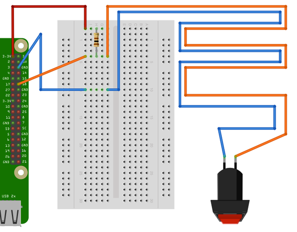
Figure 12-9. Using an external pull-up resistor
See Also
For the basics of connecting a button, see Recipe 12.1.
12.7 Using a Rotary (Quadrature) Encoder
Solution
Use a rotary (quadrature encoder) connected to two GPIO pins, as shown in Figure 12-10.
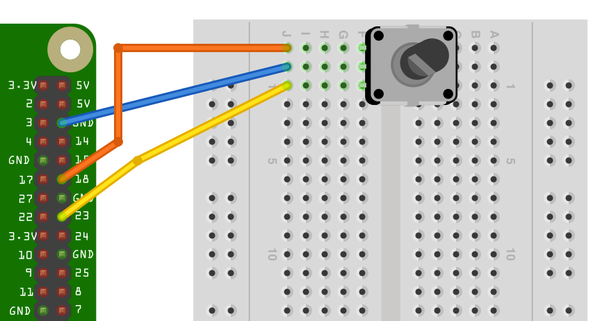
Figure 12-10. Connecting a rotary encoder
To make this recipe, you will need:
-
Breadboard and jumper wires (see “Prototyping Equipment”)
-
Rotary encoder (quadrature type; see “Miscellaneous”)
This type of rotary encoder is called a quadrature encoder, and it behaves like a pair of switches. The sequence in which they open and close as the rotary encoder’s shaft is turned determines the direction of rotation.
The rotary encoder shown has the center lead as the common lead and the two leads on either side as A and B. Not all rotary encoders use this layout, so check the pinout on the datasheet for the rotary encoder that you are using. The issue is often confused further because many rotary encoders include a push switch, which will have a separate pair of contacts.
Open an editor (nano or IDLE) and paste in the following code. As with all the program examples in this book, you can also download the program from the Code section of the Raspberry Pi Cookbook website, where it is called rotary_encoder.py.
importRPi.GPIOasGPIOimporttimeGPIO.setmode(GPIO.BCM)input_A=18input_B=23GPIO.setup(input_A,GPIO.IN,pull_up_down=GPIO.PUD_UP)GPIO.setup(input_B,GPIO.IN,pull_up_down=GPIO.PUD_UP)old_a=Trueold_b=Truedefget_encoder_turn():# return -1, 0, or +1globalold_a,old_bresult=0new_a=GPIO.input(input_A)new_b=GPIO.input(input_B)ifnew_a!=old_aornew_b!=old_b:ifold_a==0andnew_a==1:result=(old_b*2-1)elifold_b==0andnew_b==1:result=-(old_a*2-1)old_a,old_b=new_a,new_btime.sleep(0.001)returnresultx=0whileTrue:change=get_encoder_turn()ifchange!=0:x=x+change(x)
The test program simply counts up as you turn the rotary encoder clockwise, and counts down when you rotate it counterclockwise.
pi@raspberrypi ~ $ sudo python rotary_encoder.py
1
2
3
4
5
6
7
8
9
10
9
8
7
6
5
4
Discussion
Figure 12-11 shows the sequence of pulses that you will get from the two contacts, A and B. You can see that the pattern repeats itself after four steps (hence the name quadrature encoder).
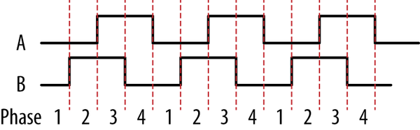
Figure 12-11. How quadrature encoders work
When rotating clockwise (left to right in Figure 12-11), the sequence will be:
| Phase | A | B |
|---|---|---|
|
1 |
0 |
0 |
|
2 |
0 |
1 |
|
3 |
1 |
1 |
|
4 |
1 |
0 |
When rotating in the opposite direction, the sequence of phases will be reversed.
| Phase | A | B |
|---|---|---|
|
4 |
1 |
0 |
|
3 |
1 |
1 |
|
2 |
0 |
1 |
|
1 |
0 |
0 |
The Python program listed previously implements the algorithm for determining the rotation direction in the function get_encoder_turn. The function will return 0 (if there has been no movement), 1 for a rotation clockwise, or -1 for a rotation counterclockwise. It uses two global variables, old_a and old_b, to store the previous states of the switches A and B. By comparing them with the newly read values, it can determine (using a bit of clever logic) which direction the encoder is turning.
The sleep period of 1 millisecond is to ensure that the next new sample does not occur too soon after the previous sample; otherwise, the transitions can give false readings.
The test program should work reliably no matter how fast you twiddle the knob on the rotary encoder; however, try to avoid doing anything time-consuming in the loop, or you may find that turn steps are missed.
See Also
You can also measure the rotated position of a knob by using a variable resistor with the step response method (Recipe 13.1) or by using an analog-to-digital converter (Recipe 13.5).
12.8 Using a Keypad
Solution
Keypads are arranged in rows and columns, with a push switch on the intersection of each row or column. To find out which key is pressed, you first connect all the row and column connections to Raspberry Pi GPIO pins. So, for a 4×3 keypad, you will need four + three pins. By scanning each column in turn (setting it to output high) and reading the value of each of the row inputs, you can determine which (if any) key is pressed.
Note that keypads show considerable variation in their pinouts.
To make this recipe, you will need:
-
Breadboard and jumper wires (see “Prototyping Equipment”)
-
4×3 keypad (see “Miscellaneous”)
-
Seven male header pins (see “Miscellaneous”)
Figure 12-12 shows the wiring diagram for the project using the SparkFun keypad listed in “Miscellaneous”. The keypad is supplied without header pins, which must be soldered onto the keypad.
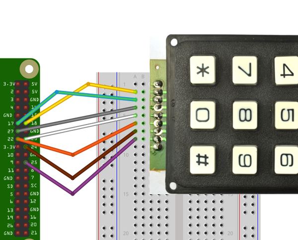
Figure 12-12. Keypad wiring diagram
Open an editor (nano or IDLE) and paste in the following code. As with all the program examples in this book, you can also download the program from the Code section of the Raspberry Pi Cookbook website, where it is called keypad.py.
Warning
Before you run the program, make sure that the row and column pins are correct for the keypad that you are using, and if necessary change the values in the variables rows and cols. If you do not do this, then it is possible that pressing a key could short one GPIO output to another, where one is high and the other is low. This would likely damage your Raspberry Pi.
The row and columns defined here are correct for the SparkFun keypad listed in “Miscellaneous” in Appendix A. The first row is connected to GPIO pin 17, the second to 25, and so on. The wiring of the row and column to the keypad connector is illustrated in Figure 12-13.
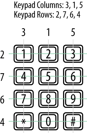
Figure 12-13. Keypad pin connections
importRPi.GPIOasGPIOimporttimeGPIO.setmode(GPIO.BCM)rows=[17,25,24,23]cols=[27,18,22]keys=[['1','2','3'],['4','5','6'],['7','8','9'],['*','0','#']]forrow_pininrows:GPIO.setup(row_pin,GPIO.IN,pull_up_down=GPIO.PUD_DOWN)forcol_pinincols:GPIO.setup(col_pin,GPIO.OUT)defget_key():key=0forcol_num,col_pininenumerate(cols):GPIO.output(col_pin,1)forrow_num,row_pininenumerate(rows):ifGPIO.input(row_pin):key=keys[row_num][col_num]GPIO.output(col_pin,0)returnkeywhileTrue:key=get_key()ifkey:(key)time.sleep(0.3)
You must run the program with superuser privileges, as it accesses the GPIO. You can see the trace from the program pressing each key in turn.
pi@raspberrypi ~ $ sudo python keypad.py
1
2
3
4
5
6
7
8
9
*
0
#
Discussion
The keys variable contains a map of the key name for each row and column position. You can customize this for your keypad.
Because there are quite a lot of pins to initialize as inputs or outputs, both the row and column pins are initialized in loops.
All the real action takes place in the get_key function. This enables each column in turn, by setting it to high. An inner loop then tests each of the rows in turn. If one of the rows is high, then the key name corresponding to that row and column is looked up in the keys array. If no keypress is detected, then the default value of key (0) is returned.
The main while loop just gets the key value and prints it. The sleep command just slows down the output.
See Also
An alternative to adding a keyboard is simply to use a USB keypad. That way you can just catch keystrokes as described in Recipe 12.11.
12.9 Detecting Movement
Solution
Use a passive infrared (PIR) motion detector module.
To make this recipe, you will need:
-
Female-to-female jumper wires (see “Prototyping Equipment”)
-
PIR motion detector module (see “Modules”)
Figure 12-14 shows how the sensor module is wired. This module expects a power supply of 5V and has an output of 3.3V, making it ideal for use with a Raspberry Pi.
Warning
Make sure that the PIR module you use has a 3.3V output. If it has 5V output, you will need to use a pair of resistors to reduce this to 3.3V (see Recipe 13.6).
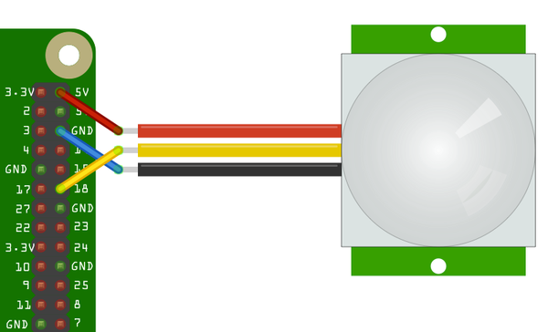
Figure 12-14. Wiring a PIR motion detector
Open an editor (nano or IDLE) and paste in the following code. As with all the program examples in this book, you can also download the program from the Code section of the Raspberry Pi Cookbook website, where it is called pir.py.
importRPi.GPIOasGPIOimporttimeGPIO.setmode(GPIO.BCM)GPIO.setup(18,GPIO.IN)whileTrue:input_state=GPIO.input(18)ifinput_state==True:('Motion Detected')time.sleep(1)
The program simply prints out the state of the GPIO input 18.
$ sudo python pir.py
Motion Detected
Motion Detected
Discussion
Once triggered, the output of the PIR sensor will stay high for a little while. You can adjust this using one of the trimpots on its circuit board. The second trimpot (if present) will set the threshold of light level that will disable the sensor. This is useful when the sensor is being used to control a light, turning it on when detecting movement, but only when its dark.
See Also
You could combine this recipe with Recipe 7.16 to send an email when an intruder is detected or integrate it with If This Then That (IFTTT) to provide a whole load of possible ways of being notified (see Recipe 15.3).
To detect movement using computer vision and a webcam, see Recipe 8.6.
12.10 Adding GPS to the Raspberry Pi
Solution
A 3.3V serial GPS module can be connected directly to Raspberry Pi’s RXD connection.
Figure 12-15 shows how the module is wired. The RXD of the Raspberry Pi connects to Tx of the GPS module. The only other connections are for GND and 5V, so we can easily just use three female-to-female headers.
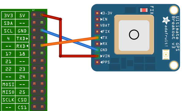
Figure 12-15. Wiring a GPS to a Raspberry Pi
GPS messages require some decoding. Fortunately, there is a good suite of tools to help us do this. Install the following packages:
$ sudo apt-get install gpsd
$ sudo apt-get install gpsd-clients
The most important of these is gpsd. This is a tool that reads GPS data from a serial or USB connection as well as other sources and makes it available for client programs to use by providing a local web service on port 2748.
To start the gpsd service running, issue the following command:
$ sudo gpsd /dev/ttyAMA0
You can see if it is working by entering the command:
$ cgps -s
The -s is optional; it just suppresses the display of the raw data (see Figure 12-16).
The third package that we installed (python-gps) is, as you might expect, a Python library for accessing the GPS data in a nice, convenient form. You will use python_gps with a short test program to display just the latitude, longitude, and time.
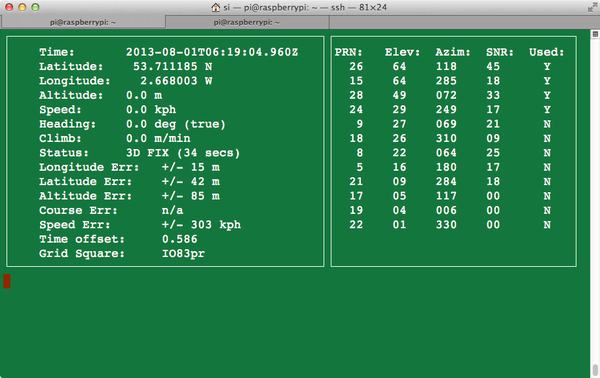
Figure 12-16. Testing GPS with cgps
Open an editor (nano or IDLE) and paste in the following code. Do not call the file gps.py, or it will conflict with the Python GPS library. As with all the program examples in this book, you can also download the program from the Code section of the Raspberry Pi Cookbook website, where it is called gps_test.py.
fromgpsimport*session=gps()session.stream(WATCH_ENABLE|WATCH_NEWSTYLE)whileTrue:report=session.next()ifreport.keys()[0]=='epx':lat=float(report['lat'])lon=float(report['lon'])("lat=%f\tlon=%f\ttime=%s"%(lat,lon,report['time']))time.sleep(0.5)
Run the program, and you should see some trace like this:
$ python gps_test.py
lat=53.710257    lon=-2.664245	time=2013-08-01T08:06:24.960Z
lat=53.710258	lon=-2.664252	time=2013-08-01T08:06:25.960Z
lat=53.710258	lon=-2.664252	time=2013-08-01T08:06:25.960Z
lat=53.710248	lon=-2.664243	time=2013-08-01T08:06:26.960Z
lat=53.710248	lon=-2.664243	time=2013-08-01T08:06:26.960Z
lat=53.710248	lon=-2.664250	time=2013-08-01T08:06:27.960Z
Discussion
The program creates a session and then establishes a stream of data to be read. The GPS will repeatedly spit out messages in different formats. The if command selects just the messages you want; those that contain the positional information. The parts of the message are stored in a dictionary from which the fields can be accessed and displayed.
Besides using the GPS data with Python, you can also use the xgps tool to display the GPS data (Figure 12-17). Just enter the command:
$ xgps
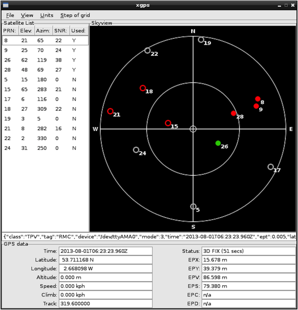
Figure 12-17. Viewing GPS with xgps
This utility requires a display, so you should run it from the Raspberry Pi itself or by using VNC (Recipe 2.8) or RDP (Recipe 2.9).
12.11 Intercepting Keypresses
Solution
There are at least two ways to solve this problem. The most straightforward is to use the sys.stdin.read function. This has the advantage over the other method of not requiring a graphical user interface to be running, so a program using it can be run from an SSH session.
Open an editor (nano or IDLE) and paste in the following code. As with all the program examples in this book, you can also download the program from the Code section of the Raspberry Pi Cookbook website, where it is called keys_sys.py.
importsys,tty,termiosdefread_ch():fd=sys.stdin.fileno()old_settings=termios.tcgetattr(fd)try:tty.setraw(sys.stdin.fileno())ch=sys.stdin.read(1)finally:termios.tcsetattr(fd,termios.TCSADRAIN,old_settings)returnchwhileTrue:ch=read_ch()ifch=='x':break("key is: "+ch)
The alternative to this is to use Pygame. Pygame is a Python library intended for writing games. It can also be used to detect keypresses. You could then use this to perform some action. This recipe must be made using Python 2 rather than Python 3, as Pygame is not included with Python 3.
The following example program illustrates the use of Pygame to print out a message each time a key is pressed. However, it only works if the program has access to the windowing system, so you will need to run it using VNC (Recipe 2.8), RDP (Recipe 2.9), or directly on the Raspberry Pi. The example code is in the file keys_pygame.py on the book’s website.
importpygameimportsysfrompygame.localsimport*pygame.init()screen=pygame.display.set_mode((640,480))pygame.mouse.set_visible(0)whileTrue:foreventinpygame.event.get():ifevent.type==QUIT:sys.exit()ifevent.type==KEYDOWN:("Code: "+str(event.key)+" Char: "+chr(event.key))
This opens a blank Pygame window, and keys will only be intercepted if the Pygame window is selected. The program produces output in the Terminal window from which the program is run.
If you press an arrow key or Shift key with the first stdin read approach, the program will throw an error because those keys don’t have an ASCII value.
$python keys_pygame.py
Code: 97 Char: a
Code: 98 Char: b
Code: 99 Char: c
Code: 120 Char: x
Code: 13 Char:
In this case, Ctrl-C won’t stop this program from running. To stop the program, click the X on the PyGame window.
Discussion
When you are using the Pygame approach, other keys have constant values defined for them, which allows you to use the cursor and other non-ASCII keys (like the up arrow key and Home) on the keyboard. This isn’t possible with the other approach.
See Also
Intercepting keyboard events can also be an alternative to using a matrix keypad (Recipe 12.8).
12.12 Intercepting Mouse Movements
Solution
The solution to this is very similar to that of using Pygame to intercept keyboard events (Recipe 12.11).
Open an editor (nano or IDLE) and paste in the following code. As with all the program examples in this book, you can also download the program from the Code section of the Raspberry Pi Cookbook website, where it is called mouse_pygame.py.
importpygameimportsysfrompygame.localsimport*pygame.init()screen=pygame.display.set_mode((640,480))pygame.mouse.set_visible(0)whileTrue:foreventinpygame.event.get():ifevent.type==QUIT:sys.exit()ifevent.type==MOUSEMOTION:("Mouse: (%d,%d)"%event.pos)
The MOUSEMOTION event is triggered whenever the mouse moves within the Pygame window. You can find the coordinates from the pos value of the event. The coordinates are absolute coordinates relative to the top-left corner of the window:
Mouse: (262, 285)
Mouse: (262, 283)
Mouse: (262, 281)
Mouse: (262, 280)
Mouse: (262, 278)
Mouse: (262, 274)
Mouse: (262, 270)
Mouse: (260, 261)
Mouse: (258, 252)
Mouse: (256, 241)
Mouse: (254, 232)
Discussion
Other events that you can intercept are MOUSEBUTTONDOWN and MOUSEBUTTONUP. These can be used to detect when the left mouse button has been pressed or released.
See Also
The Pygame documentation for mouse can be found at the Pygame website.
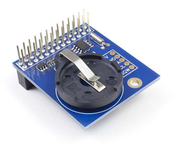
12.13 Using a Real-Time Clock Module
Solution
Use an real-time clock (RTC) module.
A very common RTC chip is the DS1307. It has an I2C interface and can be bought as a ready-to-use module that includes the chip itself, a quartz crystal for it to maintain accurate timekeeping, and a battery holder for a 3V lithium cell.
To make this recipe, you will need:
-
A DS1307 or compatible RTC module (see “Modules”)
-
Female-to-female jumper wires (see “Prototyping Equipment”)
Warning
The RTC module that you are using must be 3.3V-compatible. That means that its I2C interface should either have no pull-up resistors at all, or they should pull up to 3.3V and not 5V. When using the Adafruit model here, simply don’t include the two resistors when soldering together the module. If you have a ready-made module, carefully remove any pull-up resistors.
Assemble the RTC module if it is in kit form, remembering to omit pull-up resistors, and then connect the module to the Raspberry Pi, as shown in Figure 12-18.
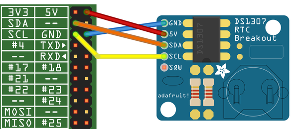
Figure 12-18. Connecting an RTC module
The DS1307 is an I2C module, so your Raspberry Pi must be set up to work with I2C (see Recipe 9.3). You can check that the device is visible using I2C tools (Recipe 9.4).
$ sudo i2cdetect -y 1
     0  1  2  3  4  5  6  7  8  9  a  b  c  d  e  f
00:          -- -- -- -- -- -- -- -- -- -- -- -- --
10: -- -- -- -- -- -- -- -- -- -- -- -- -- -- -- --
20: -- -- -- -- -- -- -- -- -- -- -- -- -- -- -- --
30: -- -- -- -- -- -- -- -- -- -- -- -- -- -- -- --
40: -- -- -- -- -- -- -- -- -- -- -- -- -- -- -- --
50: -- -- -- -- -- -- -- -- -- -- -- -- -- -- -- --
60: -- -- -- -- -- -- -- -- 68 -- -- -- -- -- -- --
70: -- -- -- -- -- -- -- --
The 68 in the table indicates that the RTC module is connected to the I2C bus at hex address 68.
If you are using one of the original Raspberry Pi model B, revision 1, boards, then use 0 after the y option in the preceding line. The revision 1 boards were distinctive for having a black audio socket.
You now need to run the following commands so that the RTC can be used with a program called hwclock.
$ sudo modprobe rtc-ds1307
$ sudo bash
$ echo ds1307 0x68 > /sys/class/i2c-adapter/i2c-1/new_device
Once again, if you are using a revision 1 board, change i2c-1 to i2c-0.
You can now access the RTC using the following command:
$ sudo hwclock -r
Sat 01 Jan 2000 00:08:08 UTC  -0.293998 seconds
As you can see, the clock is not currently set.
To set the time on the RTC module, you first need to make sure that your Raspberry Pi has the right time. If your Pi is connected to the Internet, this should happen automatically. You can check this by using the date command:
$ date
Tue Aug 20 06:42:47 UTC 2013
If the time is wrong, you can also set it manually using date (Recipe 3.35). To transfer the Raspberry Pi system time onto the RTC module, use the following command:
$ sudo hwclock -w
You can then read the time by using the -r option:
$ sudo hwclock -r
Wed 02 Jan 2013 03:11:43 UTC  -0.179786 seconds
The RTC having the correct time is pointless unless it is used to set the correct system time in Linux when it reboots. To arrange for this to happen, you need to make a few configuration changes.
First, edit /etc/modules (using sudo nano /etc/modules) and add rtc-ds1307 to the end of the list of modules. If you have already added some modules while setting up I2C, SPI, and other options, your file might look something like this:
# /etc/modules: kernel modules to load at boot time.
#
# This file contains the names of kernel modules that should be loaded
# at boot time, one per line. Lines beginning with "#" are ignored.
# Parameters can be specified after the module name.

snd-bcm2835
i2c-bcm2708
i2c-dev
spidev
rtc-ds1307
Next, you need two commands to run automatically during startup to set the system time. So edit the file /etc/rc.local using the command sudo nano /etc/rc.local, and just before the final exit 0 line, insert the following two lines. Remember to change i2c-1 to i2c-0 if you are using a revision 1 Pi.
$ echo ds1307 0x68 > /sys/class/i2c-adapter/i2c-1/new_device
$ sudo hwclock -s
When you finish, the file should look something like this:
## In order to enable or disable this script, just change the execution# bits.## By default, this script does nothing.# Print the IP address_IP=$(hostname -I)||trueif["$_IP"];thenprintf"My IP address is %s\n""$_IP"fiechods1307 0x68 > /sys/class/i2c-adapter/i2c-1/new_device sudo hwclock -sexit0
Now, when you reboot, your Raspberry Pi should set its system time from the RTC. However, if there is an Internet connection available, this will take precedence for setting the time.
Discussion
An RTC is not essential for a Raspberry Pi by any means, since a Raspberry Pi that is connected to the Internet will automatically connect to a network time server and set its own clock. However, you may not always be using the Pi when connected to a network, in which case a hardware RTC is a good option.
See Also
AB Electronics has a neat RTC that plugs directly into the GPIO socket. This is shown in Figure 12-19.
This recipe is based on a tutorial from Adafruit.