
Second Edition
Copyright © 2016 Simon Monk. All rights reserved.
Printed in the United States of America.
Published by O’Reilly Media, Inc., 1005 Gravenstein Highway North, Sebastopol, CA 95472.
O’Reilly books may be purchased for educational, business, or sales promotional use. Online editions are also available for most titles (http://safaribooksonline.com). For more information, contact our corporate/institutional sales department: 800-998-9938 or corporate@oreilly.com.
See http://oreilly.com/catalog/errata.csp?isbn=9781491939109 for release details.
The O’Reilly logo is a registered trademark of O’Reilly Media, Inc. Raspberry Pi Cookbook, the cover image, and related trade dress are trademarks of O’Reilly Media, Inc.
While the publisher and the author have used good faith efforts to ensure that the information and instructions contained in this work are accurate, the publisher and the author disclaim all responsibility for errors or omissions, including without limitation responsibility for damages resulting from the use of or reliance on this work. Use of the information and instructions contained in this work is at your own risk. If any code samples or other technology this work contains or describes is subject to open source licenses or the intellectual property rights of others, it is your responsibility to ensure that your use thereof complies with such licenses and/or rights.
978-1-491-93910-9
[LSI]
Launched in 2011, the Raspberry Pi has found a role both as a very low-cost Linux-based computer and as a platform for embedded computing. It has proven popular with educators and hobbyists alike.
Since the first edition of this book, several million more Raspberry Pis have been sold and a number of new models of Raspberry Pi have been produced. Some models—like the models B+, A+, and Pi 2 model B+—improve the specification of this device, culminating in the Raspberry Pi 2 with quad-core processor and the Raspberry Pi Compute model, which provide the Raspberry Pi as a plugin board that can become part of a larger system.
This edition has been thoroughly updated to encompass the new models of Raspberry Pi, as well as the many changes and improvements to its Raspbian operating system.
This edition contains a new chapter on computer vision and a chapter of recipes on making Internet of Things projects with your Raspberry Pi.
This book is designed in such a way that you can read it linearly as you would a regular book, or access recipes at random. You can search the table of contents or index for the recipe that you want and then jump right to it. If the recipe requires you to know about other things, it will refer you to other recipes, rather like a cookbook might refer you to base sauces before showing you how to cook something fancier.
The world of Raspberry Pi moves quickly. With a large, active community, new interface boards and software libraries are being developed all the time. In addition to examples that use specific interface boards or software, the book also covers basic principles so that you can have a better understanding of how to use new technologies that come along as the Raspberry Pi ecosystem develops.
As you would expect, a large body of code (mostly Python programs) accompanies the book. These programs are all open source and available on GitHub. You’ll find a link to them at the Raspberry Pi Cookbook website.
For most of the software-based recipes, all you need is a Raspberry Pi. I recommend a Raspberry Pi 2 or 3. When it comes to recipes that involve making your own hardware to interface with the Raspberry Pi, I have tried to make good use of ready-made modules, as well as solderless breadboard and jumper wires to avoid the need for soldering.
For those wishing to make breadboard-based projects more durable, I suggest using prototyping boards with the same layout as a half-sized breadboard, such as those sold by Adafruit, so that the design can easily be transferred to a soldered solution.
The following typographical conventions are used in this book:
Indicates new terms, URLs, email addresses, filenames, and file extensions.
Constant widthUsed for program listings, as well as within paragraphs to refer to program elements such as variable or function names, databases, data types, environment variables, statements, and keywords.
Constant width boldShows commands or other text that should be typed literally by the user.
Constant width italicShows text that should be replaced with user-supplied values or by values determined by context.
This icon signifies a tip, suggestion, or general note.
This icon indicates a warning or caution.
This icon points you to the related video for that section.
Supplemental material (code examples, exercises, etc.) is available for download at http://www.raspberrypicookbook.com.
This book is here to help you get your job done. In general, if example code is offered with this book, you may use it in your programs and documentation. You do not need to contact us for permission unless you’re reproducing a significant portion of the code. For example, writing a program that uses several chunks of code from this book does not require permission. Selling or distributing a CD-ROM of examples from O’Reilly books does require permission. Answering a question by citing this book and quoting example code does not require permission. Incorporating a significant amount of example code from this book into your product’s documentation does require permission.
We appreciate, but do not require, attribution. An attribution usually includes the title, author, publisher, and ISBN. For example: “Raspberry Pi Cookbook, Second Edition, by Simon Monk (O’Reilly). Copyright 2016 Simon Monk, 978-1-491-93910-9.”
If you feel your use of code examples falls outside fair use or the permission given above, feel free to contact us at permissions@oreilly.com.
Safari Books Online is an on-demand digital library that delivers expert content in both book and video form from the world’s leading authors in technology and business.
Technology professionals, software developers, web designers, and business and creative professionals use Safari Books Online as their primary resource for research, problem solving, learning, and certification training.
Safari Books Online offers a range of plans and pricing for enterprise, government, education, and individuals.
Members have access to thousands of books, training videos, and prepublication manuscripts in one fully searchable database from publishers like O’Reilly Media, Prentice Hall Professional, Addison-Wesley Professional, Microsoft Press, Sams, Que, Peachpit Press, Focal Press, Cisco Press, John Wiley & Sons, Syngress, Morgan Kaufmann, IBM Redbooks, Packt, Adobe Press, FT Press, Apress, Manning, New Riders, McGraw-Hill, Jones & Bartlett, Course Technology, and hundreds more. For more information about Safari Books Online, please visit us online.
Please address comments and questions concerning this book to the publisher:
We have a web page for this book, where we list errata, examples, and any additional information. You can access this page at http://bit.ly/rasp-pi-ckbk_2e.
To comment or ask technical questions about this book, send email to bookquestions@oreilly.com.
For more information about our books, courses, conferences, and news, see our website at http://www.oreilly.com.
Find us on Facebook: http://facebook.com/oreilly
Follow us on Twitter: http://twitter.com/oreillymedia
Watch us on YouTube: http://www.youtube.com/oreillymedia
As always, I thank my wife Linda for her patience and support.
I also thank the technical reviewer Duncan Amos for his keen eye, good humor, and excellent suggestions that have without a doubt contributed greatly to this book.
Thanks also to all the O’Reilly team, especially those I met at the Cambridge office, who were very welcoming when I visited, and of course Nan Reinhardt for her diligent copyediting.
When you buy a Raspberry Pi, you are essentially buying an assembled printed circuit board. It does not even include a power supply or operating system.
The recipes in this chapter are concerned with getting your Raspberry Pi set up and ready for use.
Because the Raspberry Pi just uses standard USB keyboards and mice, most of the setup is pretty straightforward, so you will concentrate only on those tasks that are specific to the Raspberry Pi.
If you want a Raspberry Pi for general use, then you should buy a Raspberry Pi 3 or 2 model B. With four times as much memory and a quad-core processor, it will cope with most tasks much better than the Pi Zero or model A+ with their single processors. The Raspberry Pi 3 model B has the great advantage of having WiFi built in, so there’s no need for an extra USB WiFi adapter.
If, on the other hand, you are embedding a Raspberry Pi in a project for a single purpose, then using a model A+ or Pi Zero and saving a few dollars may well be an option.
Figure 1-1 shows the Pi Zero, model A+, and Raspberry Pi 2 B.
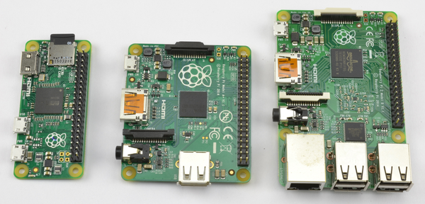
As you can see from Figure 1-1, the model A+ is smaller than the Pi 2 and has a single USB socket and no RJ45 Ethernet socket. The Pi Zero is even smaller, saving space by using a mini HDMI socket and micro USB on-the-go socket. If you want to connect a keyboard monitor and mouse to a Pi Zero, you will need adapters for both the USB and HDMI ports before you can connect standard peripherals.
The differences between all the Raspberry Pi models to date are summarized in Table 1-1.
| Model | RAM | USB sockets | Ethernet port | Notes |
|---|---|---|---|---|
| 3 B | 1 GB | 4 | yes | Includes WiFi |
| Zero | 512 MB | 1 (micro) | no | Low cost |
| 2 B | 1 GB | 4 | yes | Quad-core |
| A+ | 256 MB | 1 | no | |
| B+ | 512 MB | 4 | yes | Discontinued |
|
A |
256 MB |
1 |
no |
Discontinued |
|
B rev2 |
512 MB |
2 |
yes |
Discontinued |
|
B rev1 |
256 MB |
2 |
yes |
Discontinued |
If you have one of the older discontinued Raspberry Pi models, it is still useful. They do not have quite the performance of the latest Raspberry Pi 3 model B, but for many situations, that does not matter.
In Recipe 9.21, the Raspberry Pi Compute module will be introduced. This is designed specifically to allow a Raspberry Pi to be built into a product.
For more information on the Raspberry Pi models, see http://en.wikipedia.org/wiki/Raspberry_Pi.
The low cost of the Pi Zero makes it ideal for embedding in electronics projects without worrying about the cost. See Recipe 9.22.
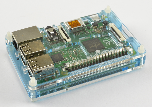
The Raspberry Pi does not come with an enclosure unless you buy one as part of a kit. This makes it a little vulnerable, as there are bare connections on the underside of the circuit board that could easily be short-circuited if the Raspberry Pi is placed on something metal.
It is a good idea to buy some protection for your Raspberry Pi in the form of a case. If you intend to use the Raspberry Pi’s GPIO pins, then the PiBow Coupé shown in Figure 1-2 is a beautiful and practical design.
There is a vast array of case styles to choose from, including:
Simple, two-part, click-together plastic boxes
VESA mountable boxes (for attaching to the back of a monitor or TV)
Lego-style boxes
3D-printed box designs
Laser-cut, snap-together acrylic designs
The case you buy is very much a matter of personal taste. However, some of the things you need to consider are:
Do you need to have access to the GPIO connector? This is important if you plan to attach external electronics to your Raspberry Pi.
Is the case well-ventilated? This is important if you plan to overclock your Raspberry Pi (Recipe 1.10) or run it hard playing videos or games, as these will all generate more heat.
You will also find heatsink kits that have tiny self-adhesive heatsinks to attach to the chips on the Raspberry Pi. These may be of some use if you are demanding a lot of your Raspberry Pi, say by playing a lot of videos, but generally they are the equivalent of “go-faster” stripes on a car.
Adafruit has a nice range of Raspberry Pi enclosures.
You will also find many styles of cases at other Raspberry Pi suppliers and on eBay.
The basic electrical specification for a power supply suitable for a Raspberry Pi is that it supplies a regulated 5V DC (direct current).
The amount of current that the power supply must be capable of providing depends both on the model of Raspberry Pi and the peripherals attached to it. It is worth getting a power supply that can easily cope with the Raspberry Pi and you should consider 700mA to be a minimum.
If you buy your power supply from the same place that you buy the Raspberry Pi, then the seller should be able to tell you if it will work with the Raspberry Pi.
If you are going to be using a WiFi dongle or other USB peripherals that use significant amounts of power, then I would get a power supply capable of 1.5A or even 2A. Also beware of very low-cost power supplies that may not provide an accurate or reliable 5V.
The power supply and connector are actually the same as those found in many smartphone chargers. If they are terminated in a micro USB plug, then they are almost certainly 5V (but check). The only question, then, is if they can supply enough current.
If they can’t, then a few bad things can happen:
They may get hot and be a potential fire risk.
They may just fail.
At times of high load (say, when the Pi is using a WiFi dongle), the voltage may dip and the Raspberry Pi may reset itself.
In general, look for a power supply that says it can supply 700mA or more. If it specifies a number of watts (W) rather than mA, divide the number of watts by 5 to get the mA figure. So, a 5V 10W power supply can supply 2A (2000mA).
Using a power supply with, say, a maximum current of 2A will not use any more electricity than a 700mA power supply. The Raspberry Pi will just take as much current as it needs.
In Figure 1-3, I measure the current taken by a Raspberry Pi model B and compare it with a Raspberry Pi 2 model B.

The newer Raspberry Pis (the A+, B+, or Raspberry Pi 2) are far more power-efficient than the older models, but when the processor is fully occupied and has a lot of peripherals attached, they can still reach similar current requirements.
In Figure 1-3, you can see that the current rarely gets above 500mA. However, the processor isn’t really doing very much here. Were you to start playing HD video, the current would increase considerably. When it comes to power supplies, it’s usually better to have something in reserve.
You can buy a module that will turn off the power when the Raspberry Pi shuts down at http://www.pi-supply.com/.
The answer to this question depends on what you intend to do with your Raspberry Pi.
For general use as a computer or for using in electronic projects, you should use Raspbian, the standard and official distribution for the Raspberry Pi.
If you plan to use your Raspberry Pi as a media center, there are a number of distributions specifically for that purpose (see Recipe 4.1).
In this book, we use the Raspbian distribution almost exclusively, although most of the recipes will work with any Debian-based distribution.
MicroSD cards are not expensive, so get a few and try out a few distributions. If you do this, it is a good idea to keep your own files on a USB flash drive so that you don’t have to keep copying them onto each microSD card.
Note that if you are using one of the upcoming recipes to write your own SD card, then you need to have a computer that has an SD card slot (many laptops do), or you can buy an inexpensive USB SD card reader.
NOOBS is by far the easiest way to get an operating system onto your Raspberry Pi.
Download the NOOBS archive file from http://www.raspberrypi.org/downloads, extract it, and place it on a microSD card. To do this, you will need a computer with an SD card slot or a USB adapter and a SD-to-microSD adapter.
Once you have downloaded the NOOBS archive file, extract it and copy the folder contents onto the SD card. Note that if the archive extracts to a folder called NOOBS_v1_3_12 or similar, it is the contents of the folder that should be copied to the root of the microSD card, not the folder itself.
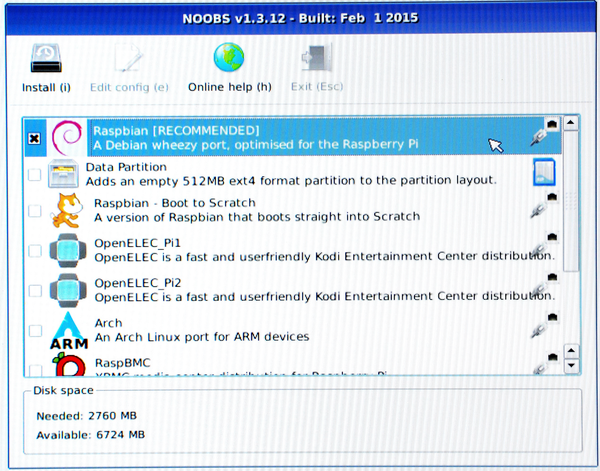
Put the microSD card containing the extracted NOOBS files into your Raspberry Pi and then power up your Raspberry Pi. When it boots, the window shown in Figure 1-4 will appear. From this screen, select Raspbian and then click the Install button.
If you are using NOOBS on an A+, you will see a shorter list of options because only the distributions for that simplified platform will be shown.
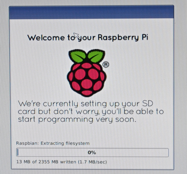
You will get a warning message that the SD card will be overwritten (which is fine) and then as the distribution is installed onto the SD card, you will see a progress screen accompanied by helpful information about the distribution (Figure 1-5).
Once the file copying is complete, you will get the message Image applied successfully. When you hit return, the Raspberry Pi will reboot and then raspi_config will automatically run so that you can configure the new installation.
Once you are up and running, the first thing you should do is connect your Raspberry Pi to the Internet (Recipes 2.1 and 2.5), open a command line by using LXTerminal (Recipe 3.2), and enter the following command to update your system to the latest version.
$ sudo apt-get update
$ sudo apt-get upgrade
This will take some time.
For NOOBS to install correctly onto a microSD card, the card must be formatted as FAT32. Most SD and microSD cards are supplied already formatted in FAT32. If you are reusing an old card and need to format it as FAT32, then use your operating system’s tool for formatting removable media.
The type of microSD card that you get will also affect how fast your Raspberry Pi runs once the operating system is installed. Look for a microSD card described as “class 10.”
You can find further information on installing an operating system with NOOBS, including information about the different distributions available at https://www.raspberrypi.org/help/noobs-setup/.
Unless you are embedding your Raspberry Pi in a project or using it as a media center, you need to attach a keyboard, mouse, monitor, and probably a WiFi dongle, unless you have a Raspberry Pi 3.
Figure 1-6 shows a typical Raspberry Pi system.
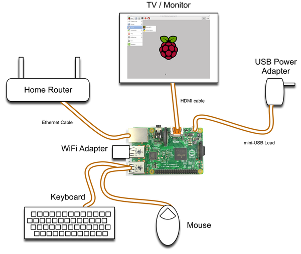
The Raspberry Pi is perfectly happy with pretty much any keyboard or mouse, wired or wireless. The exception to this is Bluetooth wireless keyboards and mice, which will not work with the Raspberry Pi.
If you have an older Raspberry Pi or a model A or A+ and run out of USB sockets, then you will also need a USB hub.
Many people have been caught out by this problem. Fortunately, it is possible to buy adapters for monitors with a DVI or VGA input but no HDMI connectors.
DVI adapters are the simplest and cheapest. They can be found for less than $5 if you search for “HDMI male to DVI female converter.”
Using VGA adapters is more complex because they require some electronics to convert the signal from digital to analog, so beware of leads that do not contain these. The official converter is called Pi-View and is available wherever the Raspberry Pi is sold. Pi-View has the advantage of having been tested and found to work with Raspberry Pi. You may find cheaper alternatives on the Internet, but often these won’t work.
eLinux has tips on what to look for in an converter.
The Raspberry Pi has two types of video output: HDMI and composite video from the audio jack, for which you need a special cord. Of these, the HDMI is much better quality. If you’re intending to use a composite video as your main screen, you may want to think again.
If you are using such a screen—say, because you need a really small screen—then you need to make a few adjustments to fit the video output to the screen. You need to make some changes to the file /boot/config.txt. You can edit it on the Raspberry Pi by issuing the following command in a Terminal session:
$ sudo nano /boot/config.txt
If the text is too small to read and you do not have an HDMI monitor, then you can also edit the file by removing the SD card from the Raspberry Pi and inserting it into your computer. The file will then be in the top-level directory on the SD card, so you can use a text editor on your PC to modify it.
You need to know the resolution of your screen. For a lot of small screens, this will be 320 by 240 pixels. Find the two lines in the file that read:
#framebuffer_width=1280
#framebuffer_height=720
Remove the # from the front of each line and change the two numbers to the width and height of your screen. In the following example, these lines have been modified to be 320 by 240:
framebuffer_width=320
framebuffer_height=240
Save the file and restart your Raspberry Pi. You should find that everything has become a lot easier to read. You will probably also find that there is a big, thick border around the screen. To adjust this, see Recipe 1.9.
There are many low-cost CCTV monitors that can make a great companion for the Raspberry Pi when you’re making something like a retro games console (Recipe 4.6). However, these monitors are often very low resolution.
For another tutorial on using composite monitors, see this Adafruit tutorial.
Also, see Recipes 1.7 and 1.9 to adjust your picture when you’re using the HDMI video output.
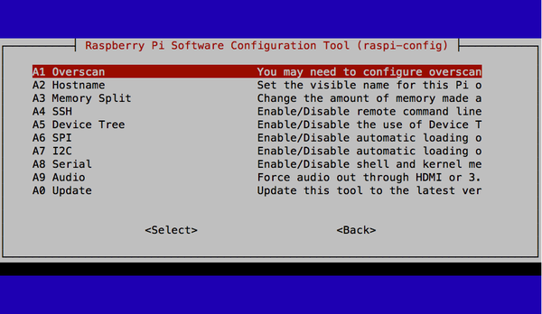
If your text extends off the screen, use the raspi-config tool to turn overscan off.
To do this, run raspi-config by opening a Terminal session and issuing the command:
$ sudo raspi-config
Then use the cursor keys to scroll down to Advanced Options and then Overscan, and turn overscan off (Figure 1-7).
If your problem is that there is a large black border around the picture, then you can reduce this (and possibly eliminate it entirely) by editing the file /boot/config.txt using the command:
$ sudo nano /boot/config.txt
Look for the section dealing with overscan. The four lines you need to change are shown in the middle of Figure 1-8.
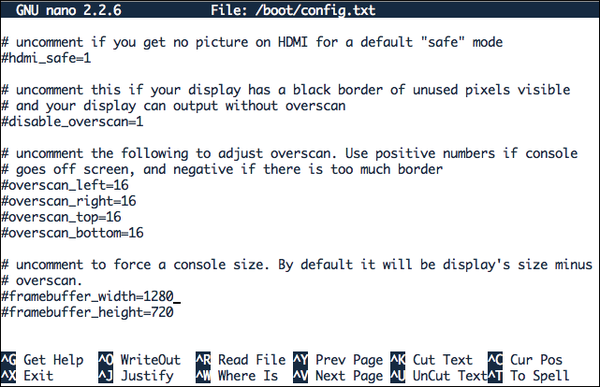
For the lines to take effect, you first need to uncomment them by removing the # character from the start of each line.
Then, using trial and error, change the settings until the screen fills as much of the monitor as possible. Note that the four numbers should be negative. Try setting them all to –20 to start with. This will increase the area of the screen that is used.
Having to repeatedly restart the Raspberry Pi to see the effects of the changes in resolution is a little tedious. Fortunately, you will only have to do this procedure once. Many monitors and TVs work just fine without any adjustments.
You can find much more information about the raspi-config tool at http://elinux.org/RPi_raspi-config.
If you have a Raspberry Pi 2 with its quad-core processor, you are unlikely to find it to be too slow. However, the older single-core Raspberry Pis can be pretty sluggish.
You can increase the clock frequency of a Raspberry Pi to make it run a little faster. This will make it use a bit more power and run a little hotter (see the Discussion next).
The method of overclocking described here is called dynamic overclocking because it automatically monitors the temperature of the Raspberry Pi and drops the clock speed back down if things start to get too hot.
To make your Pi overclock, run the raspi_config utility by issuing the following command in a Terminal:
$ sudo raspi-config
Select the Overclock option in the menu, and you are presented with the options in Figure 1-9.
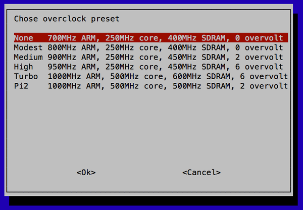
Select an option. If you find that your Raspberry Pi starts to become unstable and hangs unexpectedly, then you may need to choose a more conservative option or turn overclocking off by setting it back to None.
The performance improvements from overclocking can be quite dramatic. To measure these, I used a Raspberry Pi model B, revision 2, without a case at an ambient room temperature of 15 degrees C.
The test program was the following Python script. This just hammers the processor and is not really representative of the other things that go on in a computer, such as writing to the SD card, graphics, and so on. But it does give a good indication of raw CPU performance if you want to test the effect of overclocking on your Raspberry Pi.
importtimedeffactorial(n):ifn==0:return1else:returnn*factorial(n-1)before_time=time.clock()foriinrange(1,10000):factorial(200)after_time=time.clock()(after_time-before_time)
Check out the results of the test in Table 1-2.
| Speed test | Current | Temperature (degrees C) | |
|---|---|---|---|
| 700 MHz | 15.8 seconds | 360mA | 27 |
| 1 GHz | 10.5 seconds | 420mA | 30 |
As you can see, the performance has increased by 33% but at a cost of drawing more current and a slightly higher temperature.
A well-ventilated enclosure will help to keep your Raspberry Pi running at full speed. There have also been some efforts to add water-cooling to the Raspberry Pi. Frankly, this is just silly.
You can find much more information about the raspi-config tool at http://elinux.org/RPi_raspi-config.
You can use the raspi-config tool to change your password. Run the raspi_config utility by issuing the following command in a Terminal (see Recipe 3.2):
$ sudo raspi-config
Then select the change_pass option in the menu and follow the prompts shown in Figure 1-10.
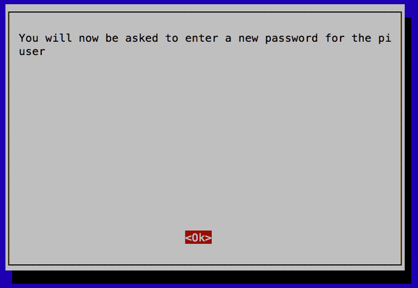
Changing your password is one occasion where you do not have to restart your Raspberry Pi for the changes to take effect.
You can also change the password from a Terminal session simply by using the passwd command as follows:
$ passwd
Changing password for pi.
(current) UNIX password:
Enter new UNIX password:
Retype new UNIX password:
passwd: password updated successfully
You can find much more information about the raspi-config tool at http://elinux.org/RPi_raspi-config.
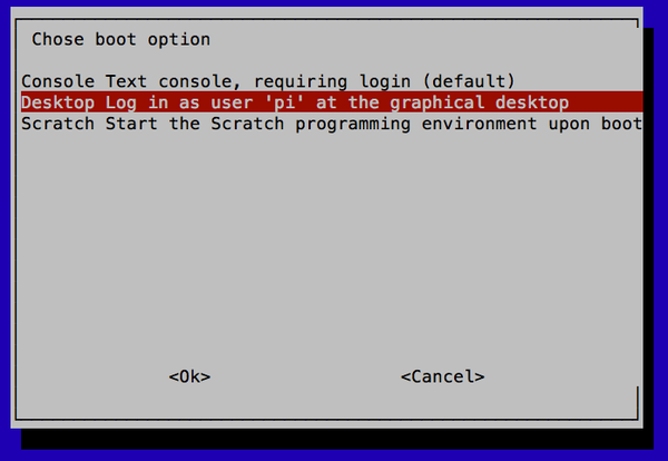
You can use the raspi-config tool to change the boot behavior so that the Raspberry Pi automatically logs you in and starts the desktop. Run the raspi_config utility by issuing the following command in a Terminal:
$ sudo raspi-config
Then select the Enable Boot to Desktop/Scratch option and then “Desktop Log in as user pi”(Figure 1-11).
After you change the boot option, you are prompted to restart your Raspberry Pi for the changes to take effect.
You can find much more information about the raspi-config tool at http://elinux.org/RPi_raspi-config.
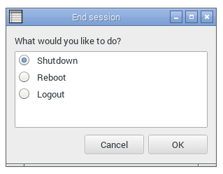
Click on the Raspberry menu in the top-left corner of the desktop. This will display a number of options (Figure 1-12).
Shuts down the Raspberry Pi. You will need to unplug the power and plug it in again to get the Raspberry Pi to boot up again.
Reboots the Raspberry Pi.
Logs you out and displays a prompt to enter your login credentials so that you can log back in.
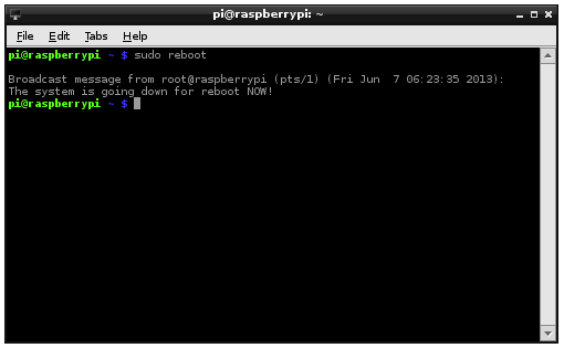
You can also reboot from the command line by issuing the command:
sudo reboot
You may have to do this after installing some software. When you do reboot, you see the message shown in Figure 1-13, which illustrates the multiuser nature of Linux and warns all users connected to the Pi.
It is better to shut your Raspberry Pi down as described above than to simply pull out the power plug, because the Raspberry Pi may be in the middle of writing to the microSD card as you power it down. This could lead to file corruption.
Unlike shutting down most computers, shutting down a Raspberry Pi does not actually turn off the power. It goes into a low-power mode—and it is a pretty low-power device anyway (but the Raspberry Pi hardware has no control over its power supply).
You can buy a module that will turn off the power when the Raspberry Pi shuts down at http://www.pi-supply.com/.
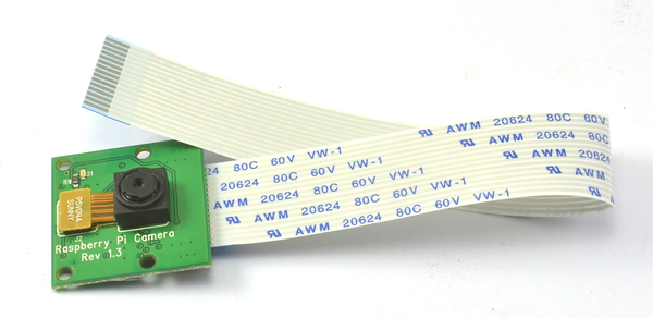
You want to use the Raspberry Pi camera module (see Figure 1-14).
The Raspberry Pi camera module (Figure 1-14) is attached to a Raspberry Pi by a ribbon cable.
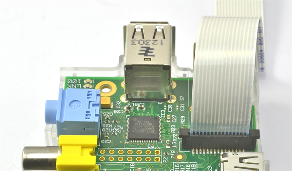
This cable attaches to a special connector between the audio and HDMI sockets on a Raspberry Pi 2. On an original Raspberry Pi model B, the connector is just behind the Ethernet socket. To fit it, pull up the levers on either side of the connector so that they unlock, and then press the cable into the slot with the connector pads of the cable facing away from the Ethernet socket. Press the two levers of the connector back down to lock the cable in place (Figure 1-15).
The camera module packaging states that it is sensitive to static. Before handling it, ground yourself by touching something grounded like the metal case of a PC.
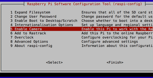
The camera module requires some software configuration. The easiest way to configure it is to use raspi_config. To run raspi-config, enter the following command into a Terminal session:
$ sudo raspi-config
You will see the Enable Camera option (Figure 1-16).
Two commands are available for capturing still images and videos: raspiStill and raspivid.
To capture a single still image, use the raspiStill command as shown here:
$ raspistill -o image1.jpg
A preview screen displays for about five seconds and then takes a photograph and stores it in the file image1.jpg in the current directory.
To capture video, use the command raspivid:
$ raspivid -o video.h264 -t 10000
The number on the end is the recording duration in milliseconds—in this case, 10 seconds.
Both raspstill and raspivid have a large number of options. If you type either command without any parameters, help text displays options that are available.
The camera module is capable of high-resolution stills and video recording.
Here are some of the key features of the camera:
5-megapixel sensor
Fixed focus f/2 lens
Still resolution 1920×1080
Video 1080p, 30fps
An alternative to the camera module is to use a USB webcam (see Recipe 8.2).
The RaspiCam documentation includes raspstill and raspivid.
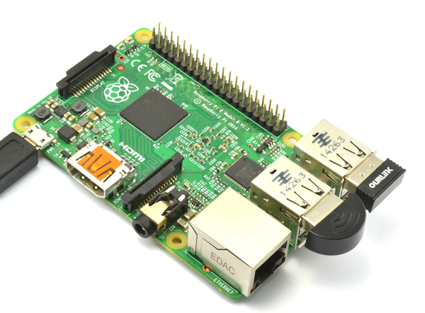
Attach a USB Bluetooth adapter to the Raspberry Pi and install the supporting Bluetooth software.
Not all Bluetooth adapters are compatible with the Raspberry Pi. Most are, but to be sure, buy one that is advertised as working with the Raspberry Pi. Figure 1-17 shows a Raspberry Pi 2 equipped with both a USB Bluetooth adapter (nearest to the camera) and a USB WiFi adapter.
To install the software needed to support Bluetooth, enter the following commands:
$ sudo apt-get update
$ sudo apt-get install bluetooth bluez-utils blueman bluez
$ sudo usermod -G bluetooth -a pi
These commands should work for all Bluetooth adapters supported by the Raspberry Pi.
Plug your Bluetooth adapter in and then reboot your Raspberry Pi (Recipe 1.13).
You will now find a new entry on the Raspbian Start menu under the Preferences section called Bluetooth Manager. Open this utility and click Search to look for nearby Bluetooth devices (Figure 1-18). Make sure that there are some Bluetooth devices set to be discoverable.
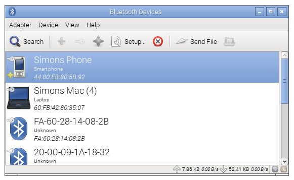
From the Bluetooth Manager, you can pair with other Bluetooth devices, send them files, and configure the visibility of your Raspberry Pi to other Bluetooth devices.
For a list of Bluetooth adapters that are compatible with the Raspberry Pi, see http://elinux.org/RPi_USB_Bluetooth_adapters.
The Raspberry Pi is designed to be connected to the Internet. Its ability to communicate on the Internet is one of its key features and opens up all sorts of possible uses, including home automation, web serving, network monitoring, and so on.
The connection can be wired through an Ethernet cable (at least in the case of the model B), or the Pi can use a USB WiFi module to provide a network connection.
Having a connected Raspberry Pi also means that you can connect to it remotely from another computer. This is very useful in situations where the Raspberry Pi itself is inaccessible and does not have a keyboard, mouse, and monitor attached to it.
This chapter gives you recipes for connecting your Raspberry Pi to the Internet and controlling it remotely over a network.
First, if you have a Raspberry Pi model A, A+, or Zero, there is no RJ45 connector for Ethernet. In this case, your best option for Internet access is to use a wireless USB adaptor (see Recipe 2.5).
If you have a Raspberry Pi model B, plug an Ethernet patch cable into its RJ45 socket and then connect the other end to a spare socket on the back of your home router. Figure 2-1 shows an original Raspberry Pi 1 where the Network LEDs are next to the audio socket. On a Raspberry Pi 2, the LEDs are built into the Ethernet socket itself.
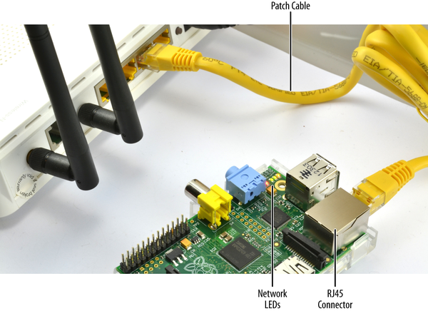
The network LEDs on your Raspberry Pi should immediately start to flicker as the Raspberry Pi connects to your network.
Raspbian is preconfigured to connect to any network using Dynamic Host Configuration Protocol (DHCP). It will automatically be assigned an IP address as long as DHCP is enabled on your network.
If the network LEDs on your Raspberry Pi do not light up when you plug it into the home router, check that you have not used the Uplink RJ45 socket on the hub or try a different cable.
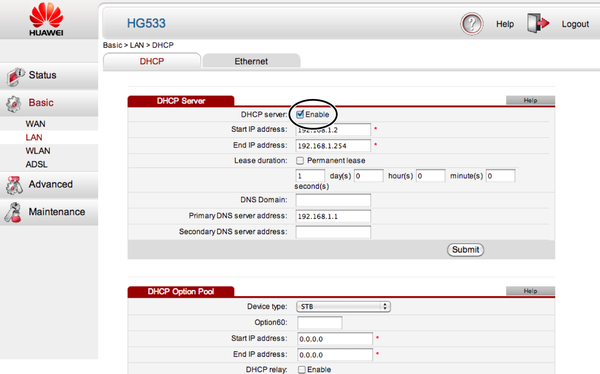
If the LEDs blink but you cannot connect to the Internet on your Raspberry Pi using a browser, check that DHCP is enabled on your network management console. Look for an option like that shown in Figure 2-2.
To connect to a wireless network, see Recipe 2.5.
You want to know the IP address of your Raspberry Pi so that you can communicate with it, whether connecting to it as a web server, exchanging files, or controlling it remotely with SSH (Recipe 2.7) or VNC (Recipe 2.8).
An IP address is a four-part number uniquely identifying a computer’s network interface within a network. Each part is separated by a dot.
To find the IP address of your Raspberry Pi, you need to issue this command in a Terminal window:
$ hostname -I
192.168.1.16
This is the local IP address of your Raspberry Pi on your home network.
A Raspberry Pi can have more than one IP address (i.e., one for each network connection). So if you have both a wired connection and a wireless connection to your Pi, it would have two IP addresses. Normally, however, you would only connect it by one method or the other, not both. To see all the network connections, use the ifconfig command:
$ sudo ifconfig

eth0      Link encap:Ethernet  HWaddr b8:27:eb:d5:f4:8f
          inet addr:192.168.1.16  Bcast:192.168.255.255  Mask:255.255.0.0
          UP BROADCAST RUNNING MULTICAST  MTU:1500  Metric:1
          RX packets:1114 errors:0 dropped:1 overruns:0 frame:0
          TX packets:1173 errors:0 dropped:0 overruns:0 carrier:0
          collisions:0 txqueuelen:1000
          RX bytes:76957 (75.1 KiB)  TX bytes:479753 (468.5 KiB)

lo        Link encap:Local Loopback
          inet addr:127.0.0.1  Mask:255.0.0.0
          UP LOOPBACK RUNNING  MTU:16436  Metric:1
          RX packets:0 errors:0 dropped:0 overruns:0 frame:0
          TX packets:0 errors:0 dropped:0 overruns:0 carrier:0
          collisions:0 txqueuelen:0
          RX bytes:0 (0.0 B)  TX bytes:0 (0.0 B)

wlan0     Link encap:Ethernet  HWaddr 00:0f:53:a0:04:57
          inet addr:192.168.1.13  Bcast:192.168.255.255  Mask:255.255.0.0
          UP BROADCAST RUNNING MULTICAST  MTU:1500  Metric:1
          RX packets:38 errors:0 dropped:0 overruns:0 frame:0
          TX packets:28 errors:0 dropped:0 overruns:0 carrier:0
          collisions:0 txqueuelen:1000
          RX bytes:6661 (6.5 KiB)  TX bytes:6377 (6.2 KiB)
Looking at the results of running this ifconfig, you can see that the Pi in question is connected by both a wired connection (eth0) with an IP address of 192.168.1.16, and a wireless one (wlan0) with an IP address of 192.168.1.13. The lo network interface is a virtual interface that allows the computer to communicate with itself.
Another way to find your IP address is to connect to the management console of your home hub and find the LAN page and then the IP table. There should be a device listed called raspberrypi with its IP address next to it.
Wikipedia has everything you want to know about IP addresses.
To set the IP address of your Raspberry Pi, whether using a wired or wireless network, you need to edit the configuration file /etc/network/interfaces.
If you view your /etc/network/interfaces file using the following command:
$ more /etc/network/interfaces
it should look something like this:
auto lo

iface lo inet loopback
iface eth0 inet dhcp

allow-hotplug wlan0
iface wlan0 inet manual
wpa-roam /etc/wpa_supplicant/wpa_supplicant.conf
iface default inet dhcp
This is telling you that Raspbian is aware of three network interfaces on your Raspberry Pi, each starting with the word iface.
loLoopback. You can ignore this.
eth0A network connection using the Ethernet socket.
wlan0A network interface using a USB WiFi adapter or the built-in WiFi hardware of the Raspberry Pi 3.
Your Raspberry Pi will have a different IP address for each network connection. In this example, you will just make the IP address for the Ethernet interface static. If you want to do the same for the WiFi interface, just edit that entry in the interfaces file instead.
To edit this file, type the following command:
$ sudo nano /etc/network/interfaces
First, decide on an IP address to use. You need to pick one that is both unused by any other machine on the network and within the allowed range of IP addresses for your home hub. In this case, I will use 192.168.1.116.
Modify the contents of the file, changing the word dhcp to static and adding the following lines:
    address 192.168.1.116
    netmask 255.255.255.0
    gateway 192.168.1.1
With the file changed as shown here, the static IP address of 192.168.1.116 has been assigned to the eth0 interface.
auto lo

iface lo inet loopback
iface eth0 inet static
    address 192.168.1.116
    netmask 255.255.255.0
    gateway 192.168.1.1

allow-hotplug wlan0
iface wlan0 inet manual
wpa-roam /etc/wpa_supplicant/wpa_supplicant.conf
iface default inet dhcp
For most networks, the netmask setting should be set to 255.255.255.0 and the gateway should be the IP address of your home router itself. This will be the same as the IP address you use to connect to the admin console of your router.
After you edit and save the file, run the following commands to clear out all the existing DHCP leases, and restart your Pi so that the changes will take effect.
$ sudo rm /var/lib/dhcp/*
$ sudo reboot
Internal IP addresses are typically something like 192.168.1.116, where just the last number is changed for each of the different computers. Another common format for internal IP addresses is 10.0.0.16.
Wikipedia has everything you want to know about IP addresses.
Changing the name of your Pi is pretty straightforward. There are just two files that need to be changed.
First, edit the file /etc/hostname. You can do this by opening a Terminal window and typing the command:
$ sudo nano /etc/hostname
Replace “raspberrypi” with a name of your choice. This should remain one word, without any punctuation or unusual characters (including the _ character.)
Second, open the file /etc/hosts in an editor using the command:
$ sudo nano /etc/hosts
The file will look something like this:
127.0.0.1       localhost
::1             localhost ip6-localhost ip6-loopback
fe00::0         ip6-localnet
ff00::0         ip6-mcastprefix
ff02::1         ip6-allnodes
ff02::2         ip6-allrouters

127.0.1.1       raspberrypi
Change the text at the end that uses the old name (“raspberrypi”) to the new name.
Restart the Pi, and you should find that the name has changed when you view it on the network from another computer.
Changing the name of your Pi can be very useful, especially if you have more than one Pi connected to your network.
See also Recipe 2.3 to change the IP address of your Raspberry Pi.
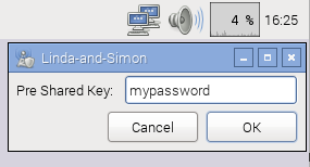
If you have the latest version of Raspbian, then setting up WiFi is really easy. Just plug in a USB WiFi adapter and then click on the Network icon at the top right of your screen (Figure 2-3). You will then be presented with a list of WiFi networks. Select your network and you will be prompted to enter your Pre Shared Key (password). Enter your password, and after a while, the Network Icon will switch to show the standard WiFi symbol and you will be connected.
If you have an older distribution of Raspbian, you will have to use the WiFi Config utility with a shortcut on the desktop. If you are not using a recent distribution, then you should update to one anyway (see Recipe 1.4).
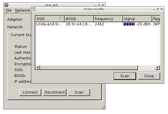
If you have a Raspberry Pi 3, then the the board already has WiFi hardware built-in. If you have an older Raspberry Pi, plug a compatible USB wireless adapter (most are compatable) into one of the USB sockets on your Raspberry Pi, and launch the WiFi Config utility (Figure 2-4). You will find the WiFi Configuration tool under the Preferences section of the Raspberry start menu. Then click the Scan button to search for access points. Double-click on the access point (for your home hub) that you want to join and then enter the password in the PSK field.
Finally, click Connect to join the network.
USB WiFi adapters can use quite a lot of power, so if you find your Pi rebooting unexpectedly or not booting properly, then you may need to use a larger power supply for it. Look for a supply that is 1.5A or more.
If you’re using a keyboard and mouse as well, you may find you’ve run out of USB sockets. In that case, a USB hub is the answer. Choosing a hub with its own power supply will also help with the power problem.
If you are using your Raspberry Pi as a media center (see Recipe 4.1), then there will be a settings page to allow you to connect the media center to your network using WiFi.
You can also set up a wireless connection by using just the command line. To do so, first edit the file /etc/network/interfaces by using the command:
$ sudo nano /etc/network/interfaces
Then find the section of the file relating to the wlan0 interface and change it to be:
allow-hotplug wlan0
iface wlan0 inet dhcp
wpa-roam /etc/wpa_supplicant/wpa_supplicant.conf
The first line specifies that the WiFi connection should automatically start when a USB WiFi dongle is inserted. The second specifies that the Raspberry Pi should allocate the IP address using DHCP. If you want to use a static IP address, replace the word dhcp with static and add in the extra lines described in Recipe 2.3 to allocate a static IP address.
The final line specifies the location of a supplicant file. This is the file that actually contains the SSID (network name) and PSK (password) for your wireless network. So, next you will edit this file using the command:
$ sudo nano /etc/wpa_supplicant/wpa_supplicant.conf
Modify the file, setting the values of ssid and pskfoobar for your wireless network.
ctrl_interface=DIR=/var/run/wpa_supplicant GROUP=netdev
update_config=1
network={
        ssid="My-Network-Name"
        psk="My-password"
        proto=RSN
        key_mgmt=WPA-PSK
        pairwise=TKIP
        auth_alg=OPEN
}
For the changes to the file to take effect, reboot your Raspberry Pi.
For wired connections, see also Recipe 2.1. For a list of WiFi adapters that are compatible with the Raspberry Pi, go to http://elinux.org/RPi_VerifiedPeripherals.
For more information on setting up a wired network, see Recipe 2.1.
Use a console cable to connect to a Raspberry Pi.
Console cables are great for a Pi that is going to be used headless—that is, without keyboard, mouse, or monitor. The console cable shown in Figure 2-5 is available from Adafruit.
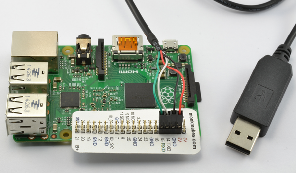
Connect the lead as follows:
Connect the red (5V) lead to the 5V pin one pin to the left of the edge of the GPIO header.
Connect the black (GND) lead to GND on the next pin to the left on the Raspberry Pi.
Connect the white lead (RX) to Raspberry Pi GPIO 14 (TXD) to the left of the black lead.
Connect the green lead (RX) to 15 (RXD) to the left of the white lead on the Raspberry Pi.
If you use a different lead, the wire colors may well be different, so always check the documentation for the lead else or you may damage your Raspberry Pi.
Note that the USB lead also provides 5V on the red wire, with enough power for the Pi on its own but not with a lot of devices attached.
If you are a Windows or Mac OS X user, you will need to install drivers for the USB lead, which are available for Windows and for Mac OS X. Linux users usually don’t need to install any drivers for these leads.
To connect to the Pi from Mac OS X, you will need to run the Terminal and enter the command:
$ sudo cu -l /dev/cu.NoZAP-PL2303-00001004 -s 115200
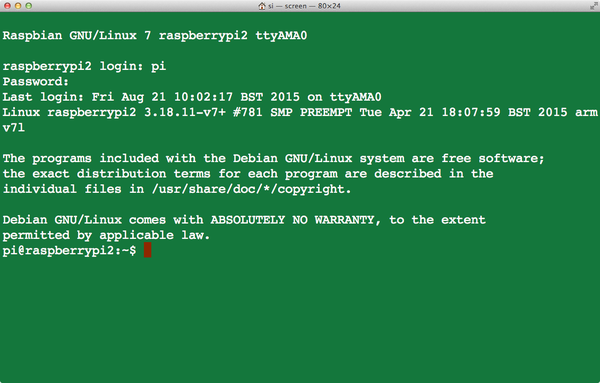
The exact device name will be different, but if you press Tab after cu.P, it will autocomplete. After connecting, press Enter, and the Raspberry Pi login prompt should appear (Figure 2-6). The default username and password are pi and raspberry, respectively.
If you are trying to connect to your Raspberry Pi from a Windows computer, you need to download the terminal software called Putty.
When you run Putty, change the “Connection type” to Serial and set the speed to 115200. You also need to set the “Serial line” to be the COM port in use by the cable. This may be COM7, but if that does not work, check into using the Windows Device manager.
When you click Open and press Enter, the Terminal session should start with a login prompt.
The console cable can be a very convenient way of using your Pi if you are traveling light, as it provides both power and a way to control the Pi remotely.
The console lead has a chip in the USB end that provides a USB-to-serial interface. This sometimes (depending on your operating system) requires the installation of drivers on your PC. The lead used here is one supplied by Adafruit (product code 954). You should be able to use any USB-to-serial converter as long as it has the necessary drivers for your PC.
Plugging the sockets of the lead into the right places is made easier if you carefully glue the four sockets together in the right order so that they fit over the GPIO header in a block.
Finding the right position on the GPIO header is made easier if you use a GPIO template like the Raspberry Leaf (see Recipe 9.1).
You can find out more about using the serial console at this Adafruit tutorial. Adafruit also sells console cables.
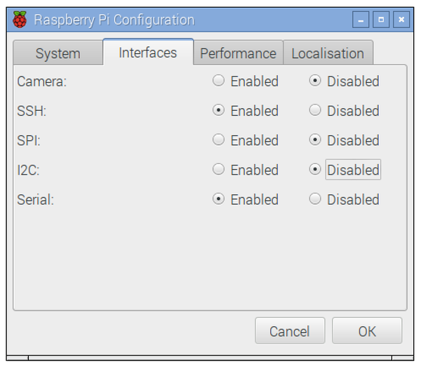
Before you can connect to your Raspberry Pi using SSH, you must enable SSH. On newer versions of Raspbian, you can use the Raspberry Pi Configuration tool (Figure 2-7) that you will find on the main menu under Preferences. Just check the box for SSH and click OK. You will be prompted to restart.
If you have an older version of Raspbian, use the raspi_config application. Start this at any time by entering the following command in Terminal:
$ sudo raspi-config
Scroll down to the SSH option and enable it.
On newer versions of Raspbian, SSH is automatically enabled and there is no setting to change.
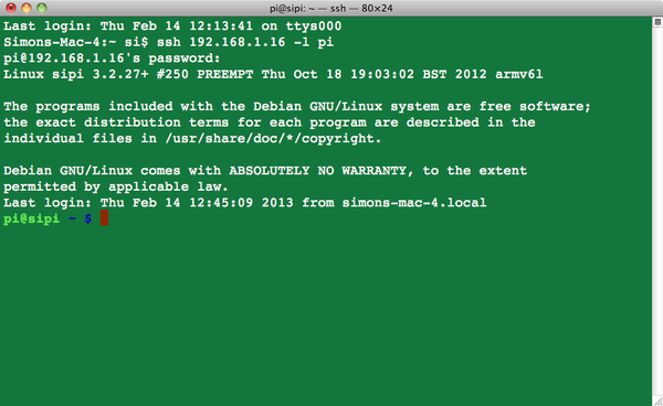
If you are using Mac OS X or have Linux installed on the computer from which you want to connect your Pi, then all you need to do to connect is open a Terminal window and enter the command:
$ ssh 192.168.1.16 -l pi
where the IP address (192.168.1.16) is the IP address of your Pi (see Recipe 2.2). You will be prompted for your password and then logged in to the Pi (Figure 2-8).
To connect from a Windows computer, you will need to use Putty (Recipe 2.6) to start an SSH session.
SSH is a very common way of connecting to remote computers; any commands that you could issue on the Pi itself, you can use from the secure shell. It is also, as the name suggests, secure because the communication is encrypted.
Perhaps the only drawback is that it is a command-line rather than graphical environment. If you need access to the full Raspberry Pi desktop environment remotely, then you need to use VNC (Recipe 2.8) or RDP (Recipe 2.9).
See also this Adafruit tutorial.
Install a Virtual Network Connection (VNC) server.
Open a Terminal session (or SSH session) on the Pi and run the following commands:
$ sudo apt-get update
$ sudo apt-get install tightvncserver
Having installed the VNC server, run it using the command:
$ vncserver :1
The first time you run this, you will be prompted to create a new password so that anyone connecting remotely has to enter the password before being granted access to the Pi.
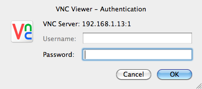
To connect to the Pi from a remote computer, you need to install a VNC client. RealVNC is a popular choice and connects well with tightvnc and is available for Windows, Linux, and Mac OS X.
When you run the client program on Mac OS X or a PC, you will be asked to enter the IP address of the VNC server you want to connect to (the IP address of your Pi). Enter “:1” after the IP address to indicate that you wish to connect to display number 1.
You will then be prompted for the password. Remember, this is the password you set previously after installing tightvncserver and is not necessarily the same as your normal Raspberry Pi password.
Although you can do most things with SSH, sometimes it is useful to have access to the graphical environment of the Pi.
If you want the VNC server to automatically start whenever you restart your Raspberry Pi, follow these steps:
$ cd /home/pi
$ cd .config
$ mkdir autostart
$ cd autostart
$ nano tightvnc.desktop
Paste the following into the editor window:
[Desktop Entry]
Type=Application
Name=TightVNC
Exec=vncserver :1
StartupNotify=false
As long as your Raspberry Pi is set to automatically log in and boot into the windowing environment, the VNC server will automatically start when you reboot.
Install the XRDP software on your Raspberry Pi by entering the following commands:
$ sudo apt-get update
$ sudo apt-get install xrdp
Once the software is installed, it will automatically start the xrdp service, which means the service will automatically start when the Raspberry Pi is rebooted.
If you have Windows 7 or later, then it already includes an RPD client for connecting to your Raspberry Pi. You will find it on your Start menu under All Programs/Accessories/Remote Desktop Connection. For older versions of Windows, you can download the client from: ModMyPi.
Mac OS X users can download the Microsoft RDP client for OS X from Microsoft’s website.
A client for Linux machines is available from http://www.rdesktop.org/.
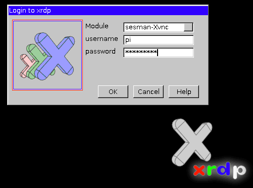
When you start your RDP client, you will be prompted for the computer you want to connect to. Enter the IP address of your Raspberry Pi. You will then be prompted for the username and password (Figure 2-10), which are the same as your usual Raspberry Pi login—that is, a username of pi and a password of raspberry unless you have changed it.
RDP does the same job as VNC but works more efficiently and therefore refreshes the contents of the screen more smoothly. The only downside is that for Mac OS X users, it does not integrate with the Share Screen feature of OS X.
See also Recipe 2.8.
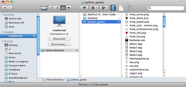
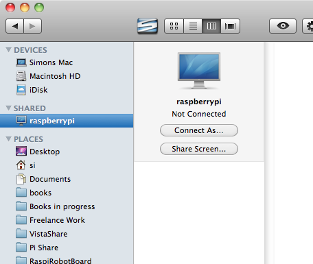
The Mac OS X operating system includes built-in support for file viewing in Finder over the network (Figure 2-11). However, you must make some configuration changes on your Raspberry Pi for OS X to pick these up.
You will need to know the IP address of your Raspberry Pi (Recipe 2.2).
Now, on the Raspberry Pi, install netatalk by using the command:
$ sudo apt-get install netatalk
Then, back on your Mac, in the Finder menu, select Go→Connect to Server and enter afp://192.168.1.16 as the server address (but use the IP address for your Raspberry Pi instead of the one shown here). Then click Connect. You will be prompted to log in. I had to reboot my Raspberry Pi before I got the login prompt.
Log in using the name pi and your password, which will be raspberry by default. The Finder should then show you the contents of your home directory on the Raspberry Pi.
There are a few more configuration changes to make on the Raspberry Pi.
$ sudo apt-get install avahi-daemon
$ sudo update-rc.d avahi-daemon defaults
Next, type the command:
$ sudo nano /etc/avahi/services/afpd.service
Paste the following code into the file:
<?xml version="1.0" standalone='no'?><!--*-nxml-*-->
<!DOCTYPE service-group SYSTEM "avahi-service.dtd">
<service-group>
   <name replace-wildcards="yes">%h</name>
   <service>
      <type>_afpovertcp._tcp</type>
      <port>548</port>
   </service>
</service-group>
To set the daemon running, type the command:
$ sudo /etc/init.d/avahi-daemon restart
Switch back to your Mac, and you should now see your Raspberry Pi in the Finder.
Being able to move files easily between your Mac and your Raspberry Pi is very useful. It means that you can use files on your Pi without having to hook up a separate keyboard, mouse, and monitor.
You can also open files on the Raspberry Pi as if they were on your Mac. This has the advantage that you can edit them with TextMate or your favorite OS X text editor.
If you’re using Windows or Linux, you can also share files by configuring your Raspberry Pi to work as Network Attached Storage (NAS); see Recipe 2.12.
The instructions here were adapted from this tutorial, which credits Matt Richardson and Shawn Wallace’s book Getting Started with Raspberry Pi (O’Reilly) as the original source.
First, follow Recipe 2.8 to install VNC. You will also need to complete Recipe 2.10.
Then enter the command:
$ sudo nano /etc/avahi/services/rfb.service
and paste the following into the editor:
<?xml version="1.0" standalone='no'?>
<!DOCTYPE service-group SYSTEM "avahi-service.dtd">
<service-group>
  <name replace-wildcards="yes">%h</name>
  <service>
    <type>_rfb._tcp</type>
    <port>5901</port>
  </service>
</service-group>
Now enter the command:
$ sudo /etc/init.d/avahi-daemon restart
You should now be able to see the Share Screen option shown in Figure 2-12. When prompted for a password, use the password you set up for VNC, not your general Raspberry Pi password.
This recipe just adds a little convenience to the process of sharing the screen of your Raspberry Pi.
If you have more than one Raspberry Pi on your network, you need to give them different names so that you can identify them on the network (Recipe 2.4).
If you are a Windows or Linux user, you can still connect to a Raspberry Pi using VNC (Recipe 2.8).
The instructions here were adapted from this tutorial, which credits Matt Richardson and Shawn Wallace’s book Getting Started with Raspberry Pi (O’Reilly) as the original source.
The solution to this problem is to install and configure Samba. To do this, issue the commands:
$ sudo apt-get install samba
$ sudo apt-get install samba-common-bin
Now, attach the USB hard drive to the Raspberry Pi. It will automatically mount in your /media folder. To check that it’s there, use the command:
$ cd /media
$ ls
The drive should be listed with whatever name you gave it when you formatted it. It will automatically mount itself whenever the Raspberry Pi reboots.
You now need to configure Samba so the drive can be shared on the network. To do this, you first need to add a Samba user (pi). Enter the following command and type in a password:
$ sudo smbpasswd -a pi
New SMB password:
Retype new SMB password:
Added user pi.
You now need to make some changes to the file /etc/samba/smb.conf, so enter the command:
$ sudo nano /etc/samba/smb.conf
The first line you’re looking for is near the top of the file:
workgroup = WORKGROUP
You only need to change this if you plan to connect from a Windows machine. This should be the name of your Windows workgroup. For Windows XP, the default is MSHOME; for newer versions of Windows, it is HOME. (But check on your Windows network.)
The next change to be made is further down the file in the Authentication section. Find the line:
# security = user
Remove the # from the front to turn security on.
Finally, scroll right to the end of the file and add the following lines:
[USB]
path = /media/NAS
comment = NAS Drive
valid users = pi
writeable = yes
browseable = yes
create mask = 0777
public = yes
Save the file and then restart Samba by entering the command:
$ sudo /etc/init.d/samba restart
If all is well, your USB drive should now be shared on your network.
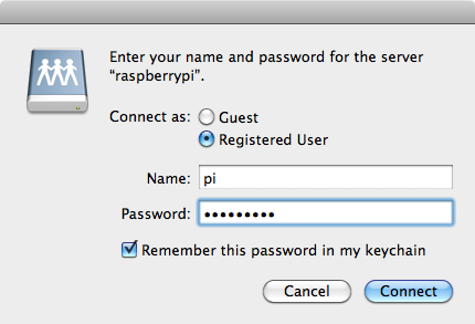
To connect to the drive on a Mac OS X, just select Go→Connect to Server from the Finder menu. Then enter smb://raspberrypi/USB in the Server Address field. You will see a login dialog box, where you need to change the username to pi (Figure 2-13).
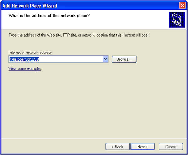
If you are connecting to the NAS from a Windows machine, the exact procedure will vary depending on your version of Windows. However, the basic principle is that at some point you will need to enter the network address, which should be \\raspberrypi\USB (Figure 2-14).
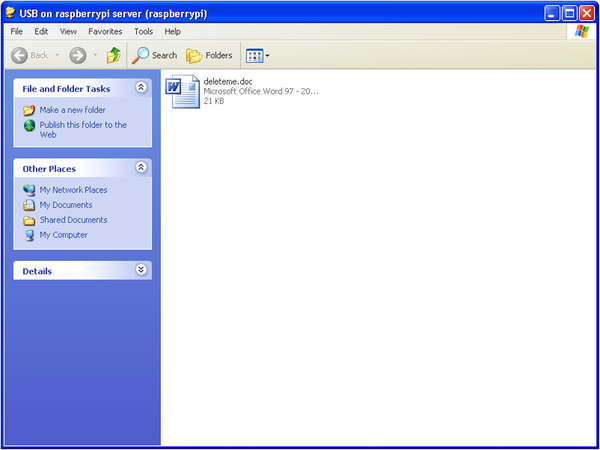
You will then be prompted for the username and password before you can use the NAS disk (Figure 2-15).
If you are a Linux user, this command should mount the NAS drive for you:
$ sudo mkdir /pishare
$ sudo smbmount -o username=pi,password=raspberry //192.168.1.16/USB /pishare
You may wish to change your Raspberry Pi’s network name to something inappropriate like piNAS (see Recipe 2.4).
Use Common Unix Printing System (CUPS).
Start by entering the following command into a Terminal to install CUPS. This may take some time.
$ sudo apt-get install cups
Give yourself admin privileges for CUPS by entering the following command:
$ sudo usermod -a -G lpadmin pi
CUPS is configured via a web interface. Neither the Midori or Dillo web browsers work very well with the CUPS administration pages, but Iceweasel works just fine. You can install the Iceweasel browser by entering the following command:
$ sudo apt-get install iceweasel
Start Iceweasel from the Internet group of your Start menu and navigate to the address http://localhost:631.
Go to the Administration tab and choose the Add Printer option. This will display a list of printers that are on the network or connected directly to the Raspberry Pi’s USB port (Figure 2-16).
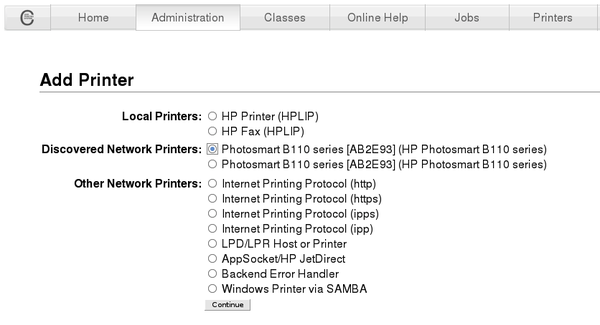
Follow the series of dialog boxes to set up the printer.
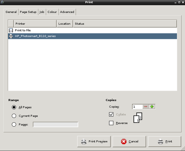
When you’re finished, you can test out the printer by firing up AbiWord (see Recipe 4.2). Type some text, and when you’re ready to print it, you should see your newly added printer available for printing (Figure 2-17).
See also the official CUPS website.
Use the File Manager.
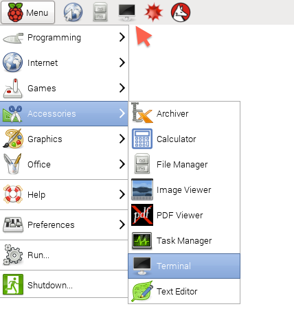
You can find this program on your Start menu in the Accessories group (Figure 3-1).
Using the File Manager, you can drag a file or directory from one directory to another or use the Edit menu to copy a file from one location and paste it to a second. This operates in much the same way as the Windows File Manager or Mac OS X Finder.
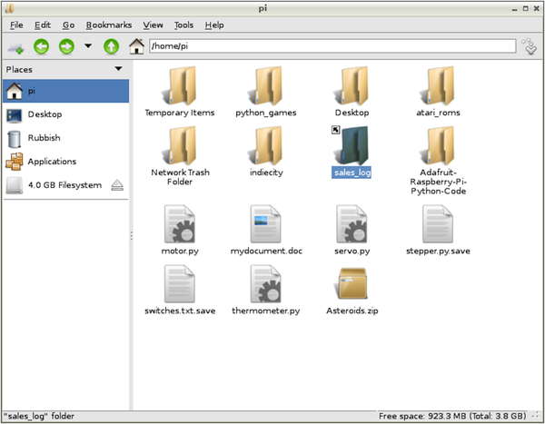
The lefthand side of the File Manager shows the volumes that are mounted, so if you connect a USB flash drive or external USB drive, it will appear here.
The central area displays the files in the current folder, which you can navigate using the buttons in the toolbar or by typing a location in the file path area at the top.
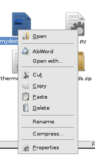
Right-click a file to reveal options that can be used on that file (Figure 3-2).
See also Recipe 3.4.
Select the LX Terminal icon (looks like a black computer monitor) at the top of the Raspberry Pi Desktop, or select the Terminal menu option on the Start menu in the Accessories group (Figure 3-3).
When the LX Terminal starts, it is set to your home directory (/home/pi).
You can open as many Terminal sessions as you want. It is often useful to have a couple of sessions open in different directories so that you don’t have to constantly switch directories using cd (Recipe 3.3).
In the next section (Recipe 3.3), you will look at navigating the directory structure using the Terminal.
The main command used for navigating the filesystem is cd (change directory). After cd, you have to specify the directory that you want to change to. This can either be a relative path to a directory inside your current directory, or an absolute path to somewhere else on the filesystem.
To see what the current directory is, you can use the command pwd (print working directory).
Try out a few examples. Open a Terminal session, and you should see a prompt like this:
pi@raspberrypi ~ $
The prompt that you will see after each command (pi@raspberrypi ~ $) is a reminder of your username (pi) and your computer name (raspberrypi). The ~ character is shorthand for your home directory (/home/pi). So, at any point, you can change your current directory to your home directory as follows:
$ cd ~
Throughout the book, I use a $ at the start of each line where you are expected to type a command. The response from the command line will not be prefixed by anything; it will appear just as it does on the Raspberry Pi’s screen.
You can confirm that the command did indeed set the directory to the home directory by using the pwd command:
$ pwd
/home/pi
If you want to move up one level in the directory structure, you can use the special value .. (two dots) after the cd command, as shown here:
$ cd ..
$ pwd
/home
As you may have deduced by now, the path to a particular file or directory is made up of words separated by a /. So the very root of the whole filesystem is /, and to access the home directory within / you would refer to /home/. Then, to find the pi directory within that, you would use /home/pi/. The final / can be omitted from a path.
Paths can also be absolute (starting with a / and specifying the full path from the root), or they can be relative to the current working directory, in which case they must not start with a /.
You will have full read and write access to the files in your home directory, but once you move into the places where system files and applications are kept, your access to some files will be restricted to read only. You can override this (Recipe 3.11), but some care is required.
Check out the root of the directory structure by entering the following commands:
$ cd /
$ ls
bin   dev  home  lost+found  mnt  proc  run   selinux  sys  usr
boot  etc  lib   media       opt  root  sbin  srv      tmp  var
The ls command (list) shows us all the files and directories underneath / the root directory. You will see that there is a home directory listed, which is the directory you have just come from.
Now change into one of those directories by using the command:
$ cd etc
$ ls
adduser.conf                   hosts.deny      polkit-1
alternatives                   hp              profile
apm                            iceweasel       profile.d
apparmor.d                     idmapd.conf     protocols
apt                            ifplugd         pulse
asound.conf                    init            python
You will notice a couple of things. First, there are a lot of files and folders listed, more than can fit on the screen at once. Use the scroll bar on the side of the Terminal window to move up and down.
Second, you will see that the files and folders have some color-coding. Files are displayed in white, whereas directories are blue.
Unless you particularly like typing, the Tab key offers a convenient shortcut. If you start typing the name of a file, pressing the Tab key allows the autocomplete feature to attempt to complete the filename. For example, if you’re going to change directory to network, type the command cd netw and then press the Tab key. Because netw is enough to uniquely identify the file or directory, pressing the Tab key will autocomplete it.
If what you have typed is not enough to uniquely identify the file or directory name, then pressing the Tab key another time will display a list of possible options that match what you have typed so far. So, if you had stopped at net and pressed the Tab key, you would see the following:
$ cd net
netatalk/ network/
You can provide an extra argument after ls to narrow down the things you want to list. Change directory to /etc and then run the following:
$ ls f*
fake-hwclock.data  fb.modes  fstab  fuse.conf

fonts:
conf.avail  conf.d  fonts.conf  fonts.dtd

foomatic:
defaultspooler  direct  filter.conf

fstab.d:
pi@raspberrypi /etc $
The * character is called a wildcard. In specifying f* after ls, we are saying that we want to list everything that starts with an f.
Helpfully, the results first list all the files within /etc that start with f, and then the contents of all the directories in that folder starting with f.
A common use of wildcards is to list all files with a certain extension (e.g., ls *.docx).
A convention in Linux (and many other operating systems) is to prefix files that should be hidden from the user by starting their name with a period. Any so-named files or folders will not appear when you type ls unless you also supply ls with the option -a. For example:
$ cd ~
$ ls -a
.                                  Desktop               .pulse
..                                 .dillo                .pulse-cookie
Adafruit-Raspberry-Pi-Python-Code  .dmrc                 python_games
.advance                           .emulationstation     sales_log
.AppleDB                           .fltk                 servo.py
.AppleDesktop                      .fontconfig           .stella
.AppleDouble                       .gstreamer-0.10       stepper.py.save
Asteroids.zip                      .gvfs                 switches.txt.save
atari_roms                         indiecity             Temporary Items
.bash_history                      .local                thermometer.py
.bash_logout                       motor.py              .thumbnails
.bashrc                            .mozilla              .vnc
.cache                             mydocument.doc        .Xauthority
.config                            Network Trash Folder  .xsession-errors
.dbus                              .profile              .xsession-errors.old
As you can see, most of the files and folders in your home directory are hidden.
See also Recipe 3.13.
Use the cp command to copy files and directories.
You can, of course, copy files by using the File Manager and its copy and paste menu options (Recipe 3.1).
The simplest example of copying in a Terminal session is to make a copy of a file within your working directory. The cp command is followed first by the file to copy, and then by the name to be given to the new file.
For example, the following example creates a file called myfile.txt and then makes a copy of it with the name myfile2.txt. You can find out more about the trick of creating a file using the > command in Recipe 3.8.
$ echo "hello" > myfile.txt
$ ls
myfile.txt
$ cp myfile.txt myfile2.txt
$ ls
myfile.txt    myfile2.txt
Although in this example, both file paths are local to the current working directory, the file paths can be to anywhere in the filesystem where you have write access. The following example copies the original file to an area /tmp, which is a location for temporary files. Do not put anything important in that folder.
$ cp myfile.txt /tmp
Note that in this case, the name to be given to the new file is not specified, just the directory where it is to go. This will create a copy of myfile.txt in /tmp with the same name of myfile.tmp.
Sometimes, rather than copying just one file, you may want to copy a whole directory full of files and possibly other directories. To copy such a directory, you need to use the -r option (for recursive). This will copy the directory and all its contents.
$ cp -r mydirectory mydirectory2
Whenever you are copying files or folders, if you do not have permission, the result of the command will tell you that. You will need to either change the permissions of the folder into which you are copying (Recipe 3.13) or copy the files with superuser privileges (Recipe 3.11).
The mv (move) command is used in a similar way to the cp command, except that the file or folder being moved is simply renamed rather than a duplicate being made.
For example, to simply rename a file from my_file.txt to my_file.rtf, you use the command:
$ mv my_file.txt my_file.rtf
Changing a directory name is just as straightforward, and you don’t need the recursive -r option you used when copying because changing a directory’s name implicitly means that everything within it is contained in a renamed directory.
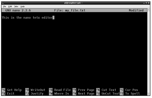
Use the editor nano included with most Raspberry Pi distributions.
To use nano, simply type the command nano followed by the name or path to the file that you want to edit. If the file does not exist, it will be created when you save it from the editor. However, this will only happen if you have write permissions in the directory where you are trying to write the file.
From your home directory, type the command nano my_file.txt to edit or create the file nano my_file.txt. Figure 3-4 shows nano in action.
You cannot use the mouse to position the cursor; use the arrow keys instead.
The area at the bottom of the screen lists a number of commands that you access by holding down the Ctrl key and pressing the letter indicated. Most of these are not that useful. The ones that you are likely to use most of the time are:
Exit. You will be prompted to save the file before nano exits.
Next page. Think of it as an arrow pointing downward. This allows you to move through a large file one screen at a time.
Previous page.
Where is. This allows you to search for a piece of text.
There are also some fairly crude cut-and-paste type options there, but in practice, it’s easier to use the normal clipboard from the menu that you access with a right-click.
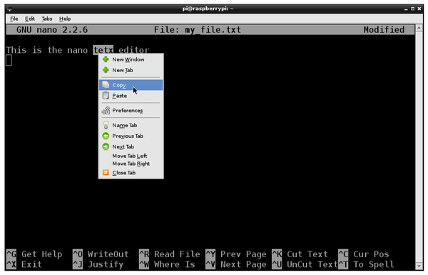
Using this clipboard also allows you to copy and paste text between other windows such as your browser.
When you’re ready to save your changes to the file and exit nano, use the command Ctrl-X. Type Y to confirm that you want to save the file. nano then displays the filename as the default name to save the file under. Press Enter to save and exit.
If you want to abandon changes you have made, enter N in place of Y.
Editors are very much a matter of personal taste. Many other editors that are available for Linux will work just fine on Raspberry Pi. The vim (vi improved) editor has many fans in the Linux world. This is also included in the popular Raspberry Pi distributions. It is not, however, an easy editor for the beginner. You can run it in the same way as nano, but using the command vi instead of nano. There are more details on using vim at http://newbiedoc.sourceforge.net/text_editing/vim.html.en.
The cat command displays the whole contents of the file, even if it is longer than will fit on the screen.
The more command just displays one screen of text at a time. Press the space bar to display the next screen.
You can also use cat to concatenate (join together) a number of files (Recipe 3.30).
Another popular command related to more is less. less is like more except it allows you to move backward in the file as well as forward.
This can be useful for quickly creating a file.
To use the more command to view files without using an editor, see Recipe 3.7.
To use > to capture other kinds of system output, see Recipe 3.29.
To create a directory, use the mkdir command. Try out the following example:
$ cd ~
$ mkdir my_directory
$ cd my_directory
$ ls
You need to have write permission in the directory within which you are trying to create the new directory.
For general information on using the Terminal to navigate the filesystem, see Recipe 3.3.
The rm (remove) command will delete a file or directory and its contents. It should be used with extreme caution.
Deleting a single file is simple and safe. The following example will delete the file my_file.txt from the home directory:
$ cd ~
$ rm my_file.txt
$ ls
You need to have write permission in the directory within which you are trying to carry out the deletion.
You can also use the * wildcard when deleting files. This example will delete all the files starting with my_file. in the current directory:
$ rm my_file.*
You could also delete all the files in the directory by typing:
$ rm *
If you want to recursively delete a directory and all its contents, including any directories that it contains, you can use the -r option:
$ rm -r mydir
When deleting files from a Terminal window, remember that you do not have the safety net of a recycle bin from which files can be undeleted. Also, generally speaking, you won’t be given the option to confirm; the files will just be immediately deleted. This can be totally devastating if you combine it with the command sudo (Recipe 3.11).
See also Recipe 3.3.
If you are concerned about accidentally deleting files or folders, you can force the rm command to confirm by setting up a command alias (Recipe 3.34).
The sudo (substitute user do) command allows you to perform actions with superuser privileges. Just prefix the command with sudo.
Most tasks that you want to perform on the command line can usually be performed without superuser privileges. The most common exceptions to this are when you’re installing new software and editing configuration files.
For example, if you try to use the command apt-get update, you will receive a number of permission denied messages:
$ apt-get update
E: Could not open lock file /var/lib/apt/lists/lock - open (13: Permission denied)
E: Unable to lock directory /var/lib/apt/lists/
E: Could not open lock file /var/lib/dpkg/lock - open (13: Permission denied)
E: Unable to lock the administration directory (/var/lib/dpkg/), are you root?
The message at the end—are you root?—gives the game away. If you issue the same command prefixed with sudo, the command will work just fine:
$ sudo apt-get update
Get:1 http://mirrordirector.raspbian.org wheezy InRelease [12.5 kB]
Hit http://archive.raspberrypi.org wheezy InRelease
Get:2 http://mirrordirector.raspbian.org wheezy/main Sources [6,241 kB]
Hit http://archive.raspberrypi.org wheezy/main armhf Packages
Ign http://archive.raspberrypi.org wheezy/main Translation-en_GB
Ign http://archive.raspberrypi.org wheezy/main Translation-en
40% [2 Sources 2,504 kB/6,241 kB 40%]
If you have a whole load of commands to run as superuser and don’t want to have to prefix each command with sudo, you can use the following command:
$ sudo sh
#
Note how the prompt changes from $ to #. All subsequent commands will be run as superuser. When you want to revert to being a regular user, enter the command:
# exit
$
To understand more about file permissions, see Recipe 3.12.
To install software using apt-get, see Recipe 3.16.
Run the command ls -l, and you will see a result like this:
$ ls -l
total 16
-rw-r--r-- 1 pi pi    5 Apr 23 15:23 file1.txt
-rw-r--r-- 1 pi pi    5 Apr 23 15:23 file2.txt
-rw-r--r-- 1 pi pi    5 Apr 23 15:23 file3.txt
drwxr-xr-x 2 pi pi 4096 Apr 23 15:23 mydir
Figure 3-6 shows the different sections of the listing information. The first section contains the permissions. In the second column, the number 1 (labeled “Files”) indicates how many files are involved. This field only makes sense if the listing entry is for a directory; if it is a file, it will mostly be just 1. The next two entries (both pi) are the owner and group of the file. The size entry (the fifth column) indicates the size of the file in bytes. The modified date will change every time the file is edited or changed and the final entry is the actual name of the file or directory.
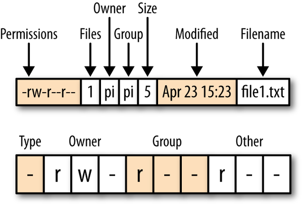
The permissions string is split into four sections (Type, Owner, Group, and Other). The first section is the type of the file. If this is a directory, it will be the character d; if it is just a file, the entry will be just a -.
The next section of three characters specifies the owner permissions for that file. Each character is a flag that is either on or off. So if the owner has read permissions, there will be a r in the first character position. If he has write permissions, there will be a w in the second slot. The third position, which is - in this example, can be x if the file is executable (a program or script) for the owner.
The third section has the same three flags but for any users in the group. Users can be organized into groups. So, in this case, the file has a user pi and a group ownership of pi. If there were any other users in the group pi, they would have the permissions specified here.
The final section specifies the permissions for any other users who are neither pi nor in the group pi.
Since most people will only ever use the Raspberry Pi as the user pi, the permissions of most interest are in the first section.
To change file permissions, see Recipe 3.13.
Common reasons why you might want to change file permissions include needing to edit a file that is marked as read-only and giving a file execute permissions so that it can run as a program or script.
The chmod command allows you to add or remove permissions for a file. There are two syntaxes for doing this; one requires the use of octal (base 8) and the other is text-based. You will use the easier-to-understand text method.
The first parameter to chmod is the change to make, and the second is the file or folder to which it should apply. This change parameter takes the form of the permission scope (+, -, = for add, remove, and set, respectively) and then the permission type.
For example, the following code will add execute (x) rights to the file for the owner of the file file2.txt.
$ chmod u+x file2.txt
If we now list the directory, we can see that the x permission has been added.
$ ls -l
total 16
-rw-r--r-- 1 pi pi    5 Apr 23 15:23 file1.txt
-rwxr--r-- 1 pi pi    5 Apr 24 08:08 file2.txt
-rw-r--r-- 1 pi pi    5 Apr 23 15:23 file3.txt
drwxr-xr-x 2 pi pi 4096 Apr 23 15:23 mydir
If we wanted to add execute permission for the group or other users, then we could use g and o, respectively. The letter a will add the permission to everyone.
For background on file permissions, see Recipe 3.12.
See Recipe 3.14 for changing file ownership.
As we discovered in Recipe 3.12, any file or directory has both an owner and a group associated with it. Since most users of the Raspberry Pi will just have the single user of pi, we don’t really need to worry about groups.
Occasionally, you will find files on your system that have been installed with a different user than pi. If this is the case, you can change the ownership of the file by using the chown command.
To just change the owner of a file, use chown followed by the new owner and group, separated by a colon, and then the name of the file.
You will probably find that you need superuser privileges to change ownership, in which case, prefix the command with sudo (Recipe 3.11).
$ sudo chown root:root file2.txt
$ ls -l
total 16
-rw-r--r-- 1 pi   pi      5 Apr 23 15:23 file1.txt
-rwxr--r-- 1 root root    5 Apr 24 08:08 file2.txt
-rw-r--r-- 1 pi   pi      5 Apr 23 15:23 file3.txt
drwxr-xr-x 2 pi   pi   4096 Apr 23 15:23 mydir
For background on file permissions, see Recipe 3.12.
Also see Recipe 3.13 for changing file permissions.
Install and use the delightfully named scrot screen capture software.
To install scrot, run the following command from Terminal:
$ sudo apt-get install scrot
The simplest way to trigger a screen capture is to just enter the command scrot. This will immediately take an image of the primary display and save it in a file named something like 2013-04-25-080116_1024x768_scrot.png within the current directory.
Sometimes you want a screenshot to show a menu being opened or something that generally disappears when the window in which you are interested loses focus. For such situations, you can specify a delay before the capture takes place using the -d option.
$ scrot -d 5
The delay is specified in seconds.
If you capture the whole screen, you can crop it later with image editing software, such as Gimp (Recipe 4.11). However, it is more convenient to just capture an area of the screen in the first place, which you can do using the -s option.
To use this option, type this command and then drag out the area of screen that you want to capture with the mouse.
$ scrot -s
The filename will include the dimensions in pixels of the image captured.
The scrot command has a number of other options to control things like using multiple screens and changing the format of the saved file. You can find out more about scrot from its manpage by entering the following command.
$ man scrot
For more information on installing with apt-get, see Recipe 3.16.
The most frequently used tool for installing software from a Terminal session is apt-get.
The basic format of the command, which you must run as a superuser, is:
$ sudo apt-get install <name of software>
For example, to install the AbiWord word processing software, you would enter the command:
$ sudo apt-get install abiword
The apt-get package manager uses a list of available software. This list is included with the Raspberry Pi operating system distribution that you use but is likely to be out-of-date. So if the software that you try to install is reported by apt-get as not found, run the following command to update the list:
$ sudo apt-get update
The list and the software packages for installation are all on the Internet, so none of this will work unless your Raspberry Pi has an Internet connection.
If you find that when you update, you get an error like E: Problem with MergeList /var/lib/dpkg/status, try running these commands:
sudo rm /var/lib/dpkg/status
sudo touch /var/lib/dpkg/status
The installation process can often take a while because the files have to be downloaded and installed. Some installations will also add shortcuts to your desktop, or the program groups on your Start menu.
You can search for software to install using the command apt-get search followed by a search string such as abiword. This will then display a list of matching packages that you could install.
See Recipe 3.17 for removing programs that you no longer need so that you can free up space.
See also Recipe 3.20 for downloading source code from GitHub.
The apt-get utility has an option (remove) that will remove a package, but it will only remove packages that have been installed with apt-get install.
For example, if you wanted to remove AbiWord, you would use the command:
$ sudo apt-get remove abiword
Removing a package like this does not always delete everything, as packages often also have prerequisite packages that are installed as well. To remove these, you can use the autoremove option, as shown here:
$ sudo apt-get autoremove abiword
$ sudo apt-get clean
The apt-get clean option will do some further tidying up of unused package installation files.
See Recipe 3.16 for installing packages using apt-get.
If you have the latest version of Raspbian, then pip will already be installed and you can run pip from the command line as shown in the example here, which is taken from Recipe 8.1 where it is used to install the Python library svgwrite.
$ sudo pip install svgwrite
If pip is not installed on your system, then you can install it by using the commands:
$ sudo apt-get install python-pip
Although many Python libraries can be installed using apt-get (see Recipe 3.16), some cannot and you must use pip.
To install software using apt-get, see Recipe 3.16.
Use the wget command to fetch a file from the Internet.
For example:
$ wget http://www.icrobotics.co.uk/wiki/images/c/c3/Pifm.tar.gz
--2013-06-07 07:35:01--  http://www.icrobotics.co.uk/wiki/images/c/c3/Pifm.tar.gz
Resolving www.icrobotics.co.uk (www.icrobotics.co.uk)... 155.198.3.147
Connecting to www.icrobotics.co.uk (www.icrobotics.co.uk)|155.198.3.147|
:80... connected.
HTTP request sent, awaiting response... 200 OK
Length: 5521400 (5.3M) [application/x-gzip]
Saving to: `Pifm.tar.gz'

100%[==================================================>] 5,521,400    601K/s

2013-06-07 07:35:11 (601 KB/s) - `Pifm.tar.gz' saved [5521400/5521400]
If your URL contains any special characters, it is a good idea to enclose it in double quotes. This example URL is from Recipe 4.10.
You will find instructions for installing software that rely on using wget to fetch files. It is often more convenient to do this from the command line rather than use a browser, find the file, download it, and then copy it to the place you need it.
The wget command takes the URL to download as its argument and downloads it into the current directory. It’s typically used to download an archive file of some type but will also download any web page.
For more information on installing with apt-get, see Recipe 3.16.
For information on selecting and using a browser, see Recipe 4.3.
To use code in Git repositories, you need to use the git clone command to fetch the files.
For example, the following command will fetch all the source code examples from this book:
$ git clone https://github.com/simonmonk/raspberrypi_cookbook_ed2.git
Modify your rc.local file to run the program you want.
Edit the file /etc/rc.local by using the command:
$ sudo nano /etc/rc.local
Add the following line after the first block of comment lines that begin with #:
$ /usr/bin/python /home/pi/my_program.py &
It is important to include the & on the end of the command line so that it is run in the background; otherwise, your Raspberry Pi will not boot.
This way of autorunning a program needs a very careful edit of rc.local, or you may stop your Raspberry Pi from booting.
A safer way of autorunning a program is detailed in Recipe 3.22.
Debian Linux, upon which most Raspberry Pi distributions are based, uses a dependency-based mechanism for automating the running of commands at startup. This is a little tricky to use and involves creating a configuration file for the script or program that you want to run in a folder called init.d.
The following example shows you how to run a Python script in your home directory. The script could do anything, but in this case, the script runs a simple Python web server, which is described further in Recipe 7.17.
The steps involved in this are:
Create an init script.
Make the init script executable.
Tell the system about the new init script.
First, create the init script. This needs to be created in the folder /etc/init.d/. The script can be called anything, but in this example, you will call it my_server.
Create the new file by using nano with the following command:
$ sudo nano /etc/init.d/my_server
Paste the following code into the editor window and save the file:
### BEGIN INIT INFO# Provides: my_server# Required-Start: $remote_fs $syslog $network# Required-Stop: $remote_fs $syslog $network# Default-Start: 2 3 4 5# Default-Stop: 0 1 6# Short-Description: Simple Web Server# Description: Simple Web Server### END INIT INFO#! /bin/sh# /etc/init.d/my_serverexportHOMEcase"$1"in start)echo"Starting My Server"sudo /usr/bin/python /home/pi/myserver.py 2>&1&;;stop)echo"Stopping My Server"PID=`ps auxwww|grep myserver.py|head -1|awk'{print $2}'`kill-9$PID;;*)echo"Usage: /etc/init.d/my_server {start|stop}"exit1;;esacexit0
This is quite a lot of work to automate the running of a script, but most of it is boiler-plate code. To run a different script, just work your way through the script, changing the descriptions and the name of the Python file you want to run.
The next step is to make this file executable for the owner, which you do using this command:
$ sudo chmod +x /etc/init.d/my_server
Now that the program is set up as a service, you can test that everything is OK before you set it to autostart as part of the boot sequence, using the following command:
$ /etc/init.d/my_server start
Starting My Server
Bottle v0.11.4 server starting up (using WSGIRefServer())...
Listening on http://192.168.1.16:80/
Hit Ctrl-C to quit.
Finally, if that runs OK, use the following command to make the system aware of the new service that you have defined:
$ sudo update-rc.d my_server defaults
For a simpler approach to making a program run automatically, see Recipe 3.21.
For more information on changing file and folder permissions, see Recipe 3.12.
Use the Linux crontab command.
To do this, the Raspberry Pi needs to know the time and date, and therefore needs a network connection or a real-time clock. See Recipe 12.13.
The command crontab allows you to schedule events to take place at regular intervals. This can be daily or hourly, and you can even define complicated patterns so different things happen on different days of the week. This is useful for backup tasks that you might want to run in the middle of the night.
You can edit the scheduled events by using the following command:
$ crontab -e
If the script or program that you want to run needs to be run by a superuser, then prefix all the crontab commands with sudo (Recipe 3.11).
The comment line indicates the format of a crontab line. The digits are, in order, minute, hour, day of month, month, day of week, and then the command that you want to run.
The first line that starts with a # is just a comment line to remind you of the format for a crontab line.
If there is a * in the digit position, that means every; if there is a number there instead, the script will only be run at that minute/hour/day of the month.
So, to run the script every day at 1 a.m., you would add the line shown in Figure 3-7.
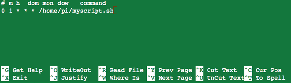
Using only a single digit, you can specify ranges to run the script just on weekdays; for example:
0 1 * * 1-5 /home/pi/myscript.sh
If your script needs to be run from a particular directory, you can use a semicolon (;) to separate multiple commands as shown here:
0 1 * * * cd /home/pi; python mypythoncode.py
You can see the full documentation for crontab by entering this command:
$ man crontab
Starting with a directory specified in the command, the find command will search, and if it finds the file, display its location. For example:
$ find /home/pi -name gemgem.py
/home/pi/python_games/gemgem.py
You can start the search higher up the tree, even at the root of the whole filesystem (/). This will make the search take a lot longer, and will also produce error messages. You can redirect these error messages by adding 2>/dev/null to the end of the line.
To search for the file throughout the entire filesystem, use the following command:
$ find / -name gemgem.py 2>/dev/null
/home/pi/python_games/gemgem.py
You can also use wildcards with find as follows:
$ find /home/pi -name match*
/home/pi/python_games/match4.wav
/home/pi/python_games/match2.wav
/home/pi/python_games/match1.wav
/home/pi/python_games/match3.wav
/home/pi/python_games/match0.wav
/home/pi/python_games/match5.wav
The find command has a number of other advanced features for searching. To see the full manpage documentation for find, use this command:
$ man find
Use the up and down arrow keys to select previous commands from the command history, and the history command with grep to find older commands.
You can access the previous command you ran by pressing the up arrow key. Pressing it again will take you to the command before that, and so on. If you overshoot the command you wanted, the down arrow key will take you back in the other direction.
If you want to cancel without running the selected command, use Ctrl-C.
Over time, your command history will grow too large to find a command that you used ages ago. To find a command from way back, you can use the history command.
$ history
    1  sudo nano /etc/init.d/my_server
    2  sudo chmod +x /etc/init.d/my_server
    3  /etc/init.d/my_server start
    4  cp /media/4954-5EF7/sales_log/server.py myserver.py
    5  /etc/init.d/my_server start
    6  sudo apt-get update
    7  sudo apt-get install bottle
    8  sudo apt-get install python-bottle
This lists all your command history and is likely to have far too many entries for you to find the one you want. To remedy this, you can pipe the history command into the grep command, which will just display results matching a search string. So, for example, to find all the apt-get (Recipe 3.16) commands that you’ve issued, you can use the line:
$ history | grep apt-get
    6  sudo apt-get update
    7  sudo apt-get install bottle
    8  sudo apt-get install python-bottle
   55  history | grep apt-get
Each history item has a number next to it, so if you find the line you were looking for, you can run it using ! followed by the history number, as shown here:
$ !6
sudo apt-get update
Hit http://mirrordirector.raspbian.org wheezy InRelease
Hit http://mirrordirector.raspbian.org wheezy/main armhf Packages
Hit http://mirrordirector.raspbian.org wheezy/contrib armhf Packages
.....
To find files rather than commands, see Recipe 3.24.
Use the Task Manager utility, which you’ll find on the Start menu in the System Tools program group (Figure 3-8).
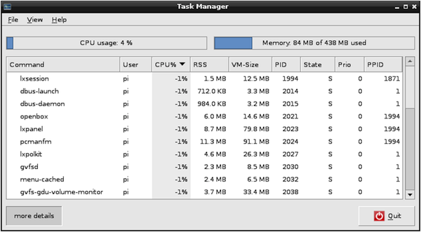
The Task Manager allows you to see at a glance how much CPU and memory are being used. You can also right-click on a process and select the option to kill it from the pop-up menu.
The graphs at the top of the window display the total CPU usage and memory. The processes are listed below that, and you can see the CPU share each is taking.
If you prefer to do this type of thing from the command line, use the Linux top command to display very similar data about processor and memory and which processes are using the most resources (Figure 3-9). You can then use the kill command to kill a process. You will need to do this as superuser.
In this case, you can see that the top process is a Python program that uses 97% of CPU. The first column shows its process ID (2447). To kill this process, enter this command:
$ kill 2447
It is quite possible to kill some vital operating system process this way, but if you do, powering off your Pi and turning it back on again will restore things to normal.
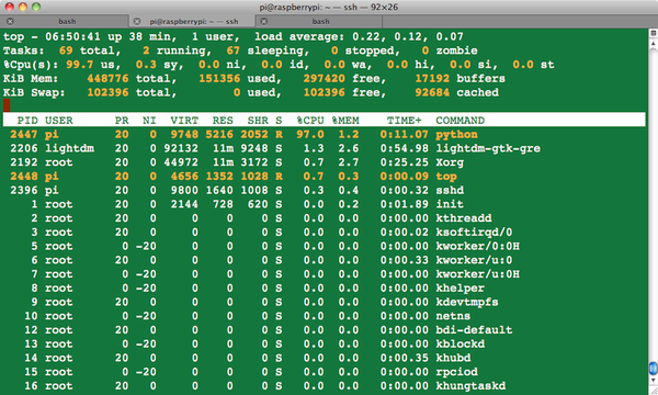
Sometimes, you may have a process running that is not immediately visible when you use top. If this is the case, you can search all the processes running by using the ps command and piping (Recipe 3.31) the results to the grep command, which will search the results and highlight items of interest.
For example, to find the process ID for our CPU-hogging Python process, we could run the following command:
$ ps -ef | grep "python"
pi        2447  2397 99 07:01 pts/0    00:00:02 python speed.py
pi        2456  2397  0 07:01 pts/0    00:00:00 grep --color=auto python
In this case, the process ID for the Python program speed.py is 2447. The second entry in the list is the process for the ps command itself.
A variation on the kill command is the killall command. Use this with caution, as it kills all processes that match its argument. So, for example, the following command will kill all Python programs running on the Raspberry Pi:
$ sudo killall python
See also the manpages for top, ps, grep, kill, and killall. You can view these by typing man followed by the name of the command, as shown here:
$ man top
If the file that you want to uncompress just has the extension .gz, you can unzip it using the command:
$ gunzip myfile.gz
You also often find files (called tarballs) that contain a directory that has been archived with the Linux tar utility and then compressed with gzip into a file with a name like myfile.tar.gz.
You can extract the original files and folders out of a tarball by using the tar command:
$ tar -xzf myfile.tar.gz
You can find out more about tar from the manpages, which you can access by using the command man tar.
Use the lsusb command. This will list all the devices attached to the USB ports on your Raspberry Pi:
$ lsusb
Bus 001 Device 002: ID 0424:9512 Standard Microsystems Corp.
Bus 001 Device 001: ID 1d6b:0002 Linux Foundation 2.0 root hub
Bus 001 Device 003: ID 0424:ec00 Standard Microsystems Corp.
Bus 001 Device 004: ID 15d9:0a41 Trust International B.V. MI-2540D [Optical mouse]
This command will tell you whether a device is connected or not, but it will not guarantee that it is working correctly. There may be drivers to install or configuration changes to make for the hardware.
For an example of using lsusb when attaching an external webcam, see Recipe 4.5.
Use the > command to redirect output that would otherwise appear on the command line.
For example, to copy a directory listing into a file called myfiles.txt, do the following:
$ ls > myfiles.txt
$ more myfiles.txt
Desktop
indiecity
master.zip
mcpi
You can use the > command on any Linux command that produces output, even if you are running, say, a Python program.
You can also use the opposite (<) command to redirect user input, although this is not nearly as useful as >.
To use cat to join together a number of files, see Recipe 3.30.
Joining files is the real purpose of the cat command. You can supply as many filenames as you like, and they will all be written to the file you direct to. If you do not redirect the output, then it will just appear in your Terminal window. If they are big files, this might take some time!
See also Recipe 3.7, where cat is used to display the contents of a file.
Use the pipe command, which is the bar symbol (|) on your keyboard, to pipe the output of one command to another. For example:
$ ls -l *.py | grep Jun
-rw-r--r-- 1 pi pi 226 Jun  7 06:49 speed.py
This example will find all the files with the extension py that also have Jun in their directory listing, indicating that they were last modified in June.
At first sight, this looks rather like output redirection using > (Recipe 3.29). The difference is that +>_ will not work where the target is another program. It will only work for redirecting to a file.
You can chain together as many programs as you like, as shown here, although this isn’t something you will do often:
$ command1 | command2 | command3
See Recipe 3.26 for an example of using grep to find a process, and Recipe 3.25 to search your command history, using a pipe and grep.
Redirect the output to /dev/null using >.
For example:
$ ls > /dev/null
This example illustrates the syntax but is otherwise pretty useless. A more common use is where you’re running a program and the developer has left a lot of trace messages in her code, which you don’t really want to see. The following example hides superfluous output from the find command (see Recipe 3.34).
$ find / -name gemgem.py 2>/dev/null
/home/pi/python_games/gemgem.py
For more information about redirecting standard output, see Recipe 3.29.
Run the program or command in the background using the & command.
For example:
$ python speed.py &
[1] 2528
$ ls
Rather than wait until the program has finished running, the command line displays the process ID (the second number) and immediately allows you to continue with whatever other commands you want to run. You can then use this process ID to kill the background process (Recipe 3.26).
To bring the background process back to the foreground, use the fg command:
$ fg
python speed.py
This will report the command or program that is running and then wait for it to finish.
Output from the background process will still appear in the Terminal.
An alternative to putting processes in the background is to just open more than one Terminal window.
For information on managing processes, see Recipe 3.26.
Edit the file ~/.bashrc using nano (Recipe 3.6), and then move to the end of the file and add as many lines as you want, like this:
alias l='ls -a'
This creates an alias called l that, when entered, will be interpreted as the command ls -a.
Save and exit the file using Ctrl-X and Ctrl-Y, and then to update the Terminal with the new alias, type the following command:
$ source .bashrc
Many Linux users set up an alias for rm like the following, so that it confirms deletions.
$ alias rm='rm -i'
This is not a bad idea, as long as you do not forget when you use someone else’s system that doesn’t have this alias set up!
For more information about rm, see Recipe 3.10.
Use the Linux date command.
The date and time format is MMDDHHMMYYYY, where MM is the month number, DD is the day of the month, HH and MM are the hours and minutes, respectively, and YYYY is the year.
For example:
$ sudo date 010203042013
Wed Jan  2 03:04:00 UTC 2013
If the Raspberry Pi is connected to the Internet, then as it boots up it will automatically set its own time using an Internet time server.
You can also use date to display the UTC time by just entering date on its own:
$ date
Wed Jan  2 03:08:14 UTC 2013
If you want your Raspberry Pi to maintain the correct time even when there is no network, then you can use a real-time clock (RTC) module (Recipe 12.13).
Use the Linux df command:
$ df -h
Filesystem      Size  Used Avail Use% Mounted on
rootfs          3.6G  1.7G  1.9G  48% /
/dev/root       3.6G  1.7G  1.9G  48% /
devtmpfs        180M     0  180M   0% /dev
tmpfs            38M  236K   38M   1% /run
tmpfs           5.0M     0  5.0M   0% /run/lock
tmpfs            75M     0   75M   0% /run/shm
/dev/mmcblk0p1   56M   19M   38M  34% /boot
To use your Raspberry Pi as a media center, you should definitely go for the superior performance of the Raspberry Pi 3 or 2 Model B, as video playing is very processor-intensive.
You can set up your Raspberry Pi as a media center during the NOOBS installation process (Recipe 1.5). Instead of selecting Raspbian as the distribution to install, select either OpenELEC_Pi1 if you have a Raspberry Pi 1 or OpenELEC_Pi2 if you have a Raspberry Pi 2.
OpenELEC is a distribution that optimizes your Raspberry Pi as a media center. It incudes the Kodi media center software, which is based on the XBMC open source project that was originally developed to convert Xbox game consoles into media centers. The code has since been ported to many platforms including the Raspberry Pi (Figure 4-1).

Raspberry Pi is perfectly capable of playing full HD video as well as streamed music, MP3 files, and Internet radio.
Kodi is a powerful piece of software with many features. Perhaps the simplest way to check that it is working is to put some music and/or video files onto a USB flash drive or external USB hard disk and connect it to the Raspberry Pi. You should be able to play them from Kodi.
Since the Raspberry Pi is likely to be sitting near your TV, you may find that your TV has a USB port that can provide enough current to run the Raspberry Pi. If this is the case, you won’t need a separate power supply.
A wireless keyboard and mouse are a good idea because if you buy them as a pair, they will use a single USB port for the dongle, which avoids the need for wires trailing all over the place. You can also buy mini-keyboards with built-in trackpads that are useful in this situation.
A wired network connection is generally higher performance and better than a WiFi connection, but it is not always convenient to have the Pi near an Ethernet socket. If this is the case, then you can set up XBMC to use a WiFi dongle for a network connection.
Setting up Kodi is very intuitive, and you can find full instructions on using the software at http://kodi.wiki/.
You can add an IR remote to Raspberry Pi to control XBMC.
Raspberry Pi is, after all, a Linux computer, so there are several office applications that you can install to use spreadsheets and word processor documents.
Programs for the Raspberry Pi are downloaded from the Internet, so you’ll need an Internet connection.
Before you install any new software, it is a good idea to open a Terminal and run the following command:
$ sudo apt-get update
To install the AbiWord word processor, run this command:
$ sudo apt-get install abiword
You will be asked to confirm the installation by typing Y; after a minute or so, installation will be complete. If you look on your Start menu, you will see a new section called Office, where you will find AbiWord (Figure 4-2).
AbiWord will open .doc, .docx, and other common word processing document formats.
If you need to use a spreadsheet, Gnumeric is a good choice. Install it by using the command:
$ sudo apt-get install gnumeric
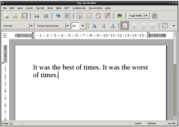
If you find that the office applications run a bit too slowly, try overclocking your Raspberry Pi (Recipe 1.10) to speed things up. A Raspberry Pi 3 or 2 will also run office applications much better than an older Raspberry Pi.
There are efforts in progress to port other office software to the Raspberry Pi, such as Libre Office (a fork of Open Office). Check the Internet for the latest news on office software ports.
See Recipe 3.16 for information on using apt-get.
You can use a number of browsers on the Raspberry Pi. The Pi is not a powerful computer, and modern browsers and web pages can put quite a load on it. This means that when you use a browser on a Raspberry Pi, there is always a trade-off between features and performance.
Chromium (Figure 4-3), as the name suggests, will be familiar to users of Google Chrome. It is full-featured but noticeably slow when you try to scroll up and down a busy web page. You can install Chromium by using the following command, which will put a new link in the Internet section of your Start menu:
$ sudo apt-get install chromium-browser

Another popular alternative to Midori is Iceweasel (Figure 4-4). This browser is based on Firefox and will perform faster than Chromium because it uses the mobile version of websites (when available), which will normally be much simpler HTML. You can download and install Iceweasel by using this command:
$ sudo apt-get install iceweasel

Since browsers require a certain amount of power for many websites, you really need a Raspberry Pi 3 or 2 to avoid a frustratingly slow experience.
For more information on installing with apt-get, see Recipe 3.16.
The Pi Store (Figure 4-5) is the Raspberry Pi equivalent of Apple’s App Store or Google’s Play Store; it is a place from which you can download, install, and run all sorts of applications, both free and for sale.
You will find a shortcut on your Start menu for the Pi Store application in the Internet section.

The first time you try to download an app, you will be asked to register. After you register, the app will download and appear in the My Library tab. To run the app, just double-click it.
This is a convenient way to browse for interesting programs to use on your Raspberry Pi. More and more apps are finding their way into the store.
See the official Pi Store website.
Download the motion software. This will allow you to set up a Raspberry Pi with a USB webcam connected to it so you can connect to a web page and view the webcam.
To install the software, enter the following command in a Terminal window:
$ sudo apt-get install motion
Plug in your USB webcam and type lsusb to see if the webcam is connected:
$ lsusb
Bus 001 Device 001: ID 1d6b:0002 Linux Foundation 2.0 root hub
Bus 001 Device 002: ID 0424:9512 Standard Microsystems Corp.
Bus 001 Device 003: ID 0424:ec00 Standard Microsystems Corp.
Bus 001 Device 004: ID 3538:0059 Power Quotient International Co., Ltd
Bus 001 Device 006: ID eb1a:299f eMPIA Technology, Inc.
If you can’t see an entry that obviously looks like a webcam, try disconnecting it, run the command again, and see if one of the entries vanishes from the list. In this case, the final entry in the list is for the webcam.
There are now a few configuration changes that you need to make. First, edit the file /etc/motion/motion.conf using the command:
$ sudo nano /etc/motion/motion.conf
This is quite a big configuration file. Right near the top of the file, you will find the line daemon off; change this to daemon on.
The other change is much further down the file. You need to change webcam_localhost = on to webcam_localhost = off.
There is one other file that you need to change. Enter the command:
$ sudo nano /etc/default/motion
Change start_motion_daemon=no to start_motion_daemon=yes.
To get the web service running, issue the command:
$ sudo service motion start
You should now be able to open your web browser and view the webcam. To do this, you will need to know the IP address of your Raspberry Pi (Recipe 2.2).
From another computer on the same network, open a browser and go to the URL http://192.168.1.16:8081/. You will need to change the URL to match the IP address of your Raspberry Pi, but keep the :8081 port number on the end of the URL.
If all goes well, you should see something like Figure 4-6.
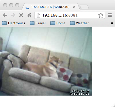
The motion software is actually really powerful; there are many other settings you can tweak to change how your webcam works.
By default, the webcam will be viewable only from within your network. If you want your webcam to be visible to the whole Internet, you need to set up port forwarding on your home hub. This will require you to log in to the admin console for the hub, look for the port forwarding option, and enable it for port 8081 for the IP address of the Raspberry Pi.
You will then be able to view the webcam by using the external IP address allocated by your ISP. This is usually shown on the front page of your admin console. But beware: unless you pay your ISP for a static IP address, this IP address is likely to change every time you restart your home hub modem.
Services such as No-ip can also be used to provide dynamic DNS, so that you can register a domain name that automatically follows changes to your IP address.
There is thorough documentation on the motion website.
You can find a list of webcams compatible with the Raspberry Pi at http://elinux.org/RPi_USB_Webcams.
The Raspberry Pi has a plug-in camera module (Recipe 1.14). At the time of writing, this is not compatible with motion, but it may be by the time you read this.
To use a webcam for computer vision projects, see Chapter 8.
See Recipe 3.16 for information on using apt-get.
There are a number of emulators around for game consoles from the 1980s. One of the most popular is Stella, an emulator for the Atari 2600 (Figure 4-7).

It is worth noting that even though these games are ancient, they are still owned by someone. The ROM image files that you need to play the games on an emulator like Stella—although easy to find on the Internet—are not necessarily yours to take. So, please stick to the law.
To install Stella, simply enter the following command in a Terminal window:
$ sudo apt-get install stella
Once it’s installed, you will find a new program in Games on your Start menu. Do not run it yet—you need to obtain the ROM image for a game.
If you are outside of the US and own the actual game, you are entitled to take a copy of the ROM image for backup purposes in many, but not all, countries. You can also find ROM images for some games that have been released without any license restrictions.
Now that you have the ROM image for the game you wish to play, create a folder called roms and place the ROM image in that folder. Then start Stella.
Click the image file to start a game. By default, the cursor keys are mapped to the joystick controls and the space bar is fire. You can change a number of settings for the emulator—for example, you almost certainly want to go to Video Settings and set it to fullscreen mode.
You can also use Input Settings and the Emul Events tab to map controller buttons to your keyboard.
The emulator uses a surprisingly large amount of the Raspberry Pi’s meager resources, so you may find that you need to use a Raspberry Pi 3 or 2.
If you search the Internet, you will find that many people have taken this basic setup and added a retro USB controller, like the widely available and quite low-cost Nintendo Retrolink USB Super SNES Classic Controller, and built the Pi and a monitor into a big arcade-style housing.
There are a number of other console emulators available—at various stages of maturity, and thus reliability—on the Raspberry Pi. One to consider is Mame, which emulates a number of different game platforms.
For more information on installing with apt-get, see Recipe 3.16.
Mojang, the original developers of Minecraft, have ported it to the Raspberry Pi and Minecraft Pi is pre-installed on the latest Raspbian distribution.
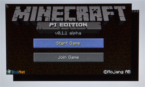
To get Minecraft to fit on the Raspberry Pi, the developers made some shortcuts in the graphics code. This means that you can only play the game directly on the Raspberry Pi with the keyboard, mouse, and monitor connected directly to it. It will not work over a remote VNC connection.
The Pi edition of Minecraft is based on the mobile version of Minecraft and lacks some features, most notably Redstone.
Find out more about the Raspberry Pi port of Minecraft.
You can also run a full version of the Minecraft Server on a Raspberry Pi (Recipe 4.8), although a Raspberry Pi 3 or 2 will perform a lot better (see Recipe 1.1).
Minecraft Pi also includes a Python programming interface, and in Recipe 7.20, you will learn how to send commands to Python over an SSH connection to do automated building.
The first step is to install the Java runtime environment by using these commands:
$ sudo apt-get update
$ sudo apt-get install openjdk-7-jdk
Then create a directory to contain the server code and fetch the spigot Minecraft server using the commands:
$ mkdir mcserver
$ cd mcserver
$ wget http://getspigot.org/spigot18/spigot_server.jar
Start the server using the command:
$ java -Xms512M -Xmx800M -jar spigot_server.jar nogui
The server will soon give you the following error message:
[15:51:26 WARN]: Failed to load eula.txt
[15:51:26 INFO]: You need to agree to the EULA in order to run
the server. Go to eula.txt for more info.
[15:51:26 INFO]: Stopping server
This is telling you that you need to accept the terms of the license agreement by editing the file called eula.txt that the server has just created for you. So, open eula.txt using nano using the command:
$ nano eula.txt
Change the line that says eula=false to eula=true and save the file, then run, and then start the server again. This time it will take several minutes to create a world and start up the server. Don’t worry, the next time you run it, it will be a lot quicker.
Eventually, the server will start and you can test it by connecting to it from another computer running Minecraft on your network.
Start Minecraft and click on Multiplayer and then Direct Connect. Enter the IP address of your Raspberry Pi (Figure 4-9) and then click Connect.
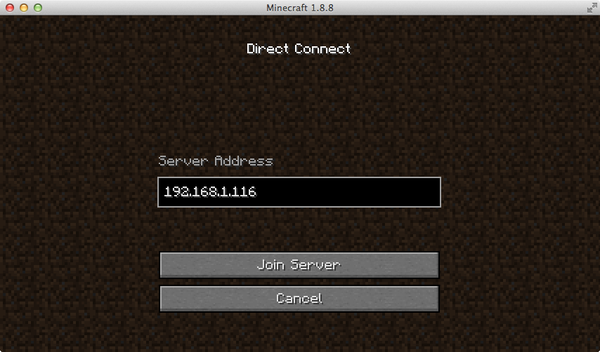
Once you are connected, you and anyone else on your network can join the server and start playing (Figure 4-10).

You will probably want to give yourself operator status in the game by typing the command:
> op YourName
where YourName is your nickname in the game.
A Raspberry Pi 2 with its four processor cores and 1 GB of memory will run a pretty decent Minecraft server. The parameters -Xms512M and -Xmx800M set the minimum and maximum amounts of memory that Java should use for the server.
The LXTerminal or SSH window will let you know when anyone connects to the server, and you can also issue various server admin commands from here. Type help for a list of commands.
When you want to stop the server, enter the command stop.
[17:41:10 INFO]: UUID of player SimonMonk is 4e3e1a27-4e7e-4bfb-b331-a30af5bd49ec
[17:41:11 INFO]: SimonMonk[/192.168.1.5:58831] logged in with entity id
382 at ([world]257.23244892748414, 67.0, 185.3728463324922)
>stop
[17:41:20 INFO]: Stopping the server
[17:41:20 INFO]: Stopping server
[17:41:20 INFO]: Saving players
[17:41:20 INFO]: SimonMonk lost connection: Server closed
[17:41:20 INFO]: SimonMonk left the game.
[17:41:21 INFO]: Saving worlds
[17:41:21 INFO]: Saving chunks for level 'world'/Overworld
[17:41:24 INFO]: Saving chunks for level 'world_nether'/Nether
[17:41:24 INFO]: Saving chunks for level 'world_the_end'/The End
>pi@Pi2headless ~/mcserver $
To allow your friends from the wider Internet to play on your server, you will need to use your router’s admin console to set up port forwarding.
You do not need to be directly connected to the Raspberry Pi to start a Minecraft server; it will work just fine if started from SSH (Recipe 2.7).
For information on running your own Minecraft server, check out http://uk.ign.com/wikis/minecraft/Admin_and_Server_Commands.
See also the Minecraft Pi edition (Recipe 4.7).
Download and run Open Arena (Figure 4-11) from the Pi Store.

Not surprisingly, you will find Open Arena in the Games section of the Pi Store. Since the game is quite violent and bloody, it comes under a plain wrapper.
Find out more about Open Arena.
For more information on using the Pi Store, see Recipe 4.4.
Be sure to check out the accompanying video for this recipe at http://razzpisampler.oreilly.com.
You want to convert your Raspberry Pi into a high-powered FM transmitter that will send a radio signal to a normal FM radio receiver (Figure 4-12).
The clever folks at Imperial College, London, have created some C code and a Python wrapper that allow you to do just this. The download even includes the theme from Star Wars to play as a sample.
All you need is a short length of wire attached to GPIO pin 4. A female-to-male header lead will work just fine for this. In fact, it should work with the radio right next to your Pi without any kind of antenna—such is the strength of the transmission.
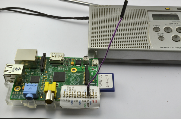
The first step is to install the pifm library using the following commands:
$ mkdir pifm
$ cd pifm
$ wget http://www.icrobotics.co.uk/wiki/images/c/c3/Pifm.tar.gz
$ tar -xzf Pifm.tar.gz
Next, find yourself an FM radio receiver and tune it to 103.0 MHz. If this frequency is already occupied by some other transmission, pick another frequency and make note of it.
Now run the following command (changing the final parameter from 103.0 if you had to change frequency):
sudo ./pifm sound.wav 103.0
If all is well, you should hear the stirring tones of the Star Wars theme.
You need to know that this project may not be legal in your country. The power output is higher than that of FM transmitters used with MP3 players.
You can play other .wav files, but they must be 16-bit 44.1kHz.
The code also includes a Python library that you can use within your own Python programs. So, you could write a user interface to allow the selection and playing of tunes.
The following fragment of code illustrates the use of the Python interface:
pi@raspberrypi ~/pifm $ sudo python
Python 2.7.3 (default, Jan 13 2013, 11:20:46)
[GCC 4.6.3] on linux2
Type "help", "copyright", "credits" or "license" for more information.
>>> import PiFm
>>> PiFm.play_sound("sound.wav")
Were you to put a Raspberry Pi in your vehicle, this would be a great way of outputting sound through the vehicle’s audio system—especially if you use the features of the latest version of pifm, which allow you to stream music to the FM transmitter from various sources.
This description is based on the original post from Imperial College London. This also includes clever tricks for piping music from various sources to pifm including from a USN microphone, which opens up all sorts of opportunities.
You want to edit an image.
Download and run the GNU image manipulation program (GIMP; see Figure 4-13).
To install GIMP, open a Terminal session and type the following command:
$ sudo apt-get install gimp
Once GIMP is installed, you’ll find a new entry in your Start menu under the Graphics heading called GNU Image Manipulation Program.
Despite being very hungry for memory and processor power, GIMP is quite usable on a Raspberry Pi model B.
Find out more from the GIMP website.
GIMP has a lot of features and is a very sophisticated image editing program, so it does take a little learning. You’ll find an online manual for the software at the GIMP website, under the Documentation tab.
For more information on installing with apt-get, see Recipe 3.16.
Install the VLC media player by running the following command:
sudo apt-get install vlc
Once it’s installed, you can find VLC in the Sound & Video section of your Start menu.
Run the program and select the Open Network Stream option on the Media menu. This will open a dialog box (see Figure 4-14) where you can enter the URL of the Internet radio station that you wish to play.
You will need to plug headphones or amplified speakers into the audio socket on the Raspberry Pi.
VLC can also be run from the command line:
$ vlc http://www.a-1radio.com/listen.pls -I dummy
VLC will probably produce a series of error messages, but then play the audio just fine.
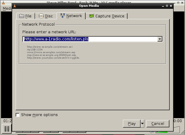
This recipe borrows heavily from this tutorial, where Jan Holst takes things a step further and adds radio-style controls to the project.
For UK readers, you can find a list of the BBC radio stream URLs online.
Although there are many languages that can be used to program the Raspberry Pi, Python is the most popular. In fact, the Pi in Raspberry Pi is inspired by the word Python.
In this chapter, you will find a host of recipes to help you get programming with Raspberry Pi.
Use both. Use Python 3 until you face a problem that is best solved by reverting to version 2.
Although the latest version of Python is Python 3 and has been for years, you will find that a lot of people stick to Python 2. In fact, in the Raspbian distribution, both versions are supplied and version 2 is just called Python, whereas version 3 is called Python 3. You even run Python 3 by using the command python3. The examples in this book are written for Python 3 unless otherwise stated. Most will run on both Python 2 and Python 3 without modification.
This reluctance on the part of the Python community to ditch the old Python 2 is largely because Python 3 introduced some changes that broke compatibility with version 2. This means that some of the huge body of third-party libraries that have been developed for Python 2 won’t work under Python 3.
My strategy is to write in Python 3 wherever possible, and revert to Python 2 when I have to because of compatibility problems.
For a good summary of the Python 2 versus Python 3 debate, see the Python wiki.
The common Raspberry Pi distributions come with the IDLE Python development tool in both the Python 2 and Python 3 versions. If you are using Raspbian, you will find shortcuts to both versions of IDLE labeled Python 2 and Python 3 in the Programming section of your Start menu (Figure 5-1).
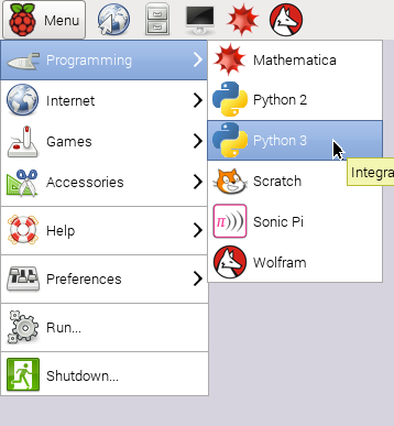
IDLE and IDLE 3 appear to be identical; the only difference is the version of Python that they use, so open IDLE 3 (Figure 5-2).
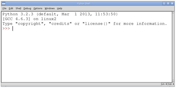
The window that opens is labeled Python Shell. This is an interactive area where you can type Python and see the results immediately. So try typing the following into the shell next to the >>> prompt:
>>>2+24>>>
Python has evaluated the expression 2 + 2 and given us the answer of 4.
The Python Shell is fine for trying things out, but if you want to write programs, then you need to use an editor. To open a new file to edit using IDLE, select New Window from the File menu (Figure 5-3).
You can now enter your program into the editor window. Just to try things, paste the following text into the editor, save the file as count.py, and then select Run Module from the Run menu. You can see the results of the program running in the Python console:
foriinrange(1,10):(i)
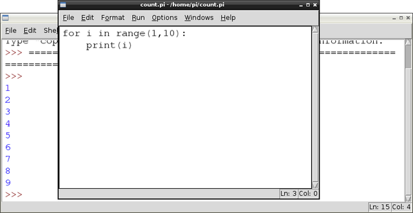
Python is unusual for a programming language in that indentation is a fundamental part of the language. Whereas many C-based languages use { and } to delimit a block of code, Python uses the indentation level. So in the preceding example, Python knows that print is to be invoked repeatedly as part of the for loop because it is indented out four spaces.
The convention used in this book is to use four spaces for a level of indentation.
When you’re starting out in Python, it’s not uncommon to see an error such as IndentationError: unexpected indent, which means that somewhere things are not indented correctly. If everything appears to line up, double-check that none of the indents contain Tab characters. Python treats tabs differently.
Notice how IDLE uses color-coding to highlight the structure of the program.
Many of the recipes in this chapter use IDLE to edit Python examples.
As well as using IDLE to edit and run Python files, you can also edit files in nano (Recipe 3.6) and then run them from a Terminal session (Recipe 5.4).
Use the Python console, either within IDLE (Recipe 5.2) or in a Terminal session.
To start a Python 2 console in a Terminal window, just type the command python; for a Python 3 console, enter the command python3.
The >>> prompt indicates that you can type Python commands. If you need to type multiline commands, then the console will automatically provide a continuation line indicated by three dots. You still need to indent any such lines, by four spaces, as shown in the following session:
>>>foriinrange(1,10):...(i)...123456789>>>
You will need to press Enter twice after your last command for the console to recognize the end of the indented block and run the code.
The Python console also provides a command history so that you can move back and forth through your previous commands using the up and down keys.
If you have more than a couple of lines that you want to type in, then chances are you would be better off using IDLE (Recipe 5.2) to edit and run a file.
Use the python or python3 command in a Terminal, followed by the filename containing the program you want to run.
To run a Python 2 program from the command line, use a command like this:
$ python myprogram.py
If you want to run the program using Python 3, then change the command python to python3. The Python program that you wish to run should be in a file with the extension .py.
You can run most Python programs as a normal user; however, there are some, especially those that use the GPIO port, that you need to run as superuser. If this is the case for your program, prefix the command with sudo:
$ sudo python myprogram.py
In the earlier examples, you have to include python in the command to run the program, but you can also add a line to the start of a Python program so that Linux knows it is a Python program. This special line is called a shebang (a contraction of hash-bang) and the following single-line example program has it as its first line.
#!/usr/bin/python
print("I'm a program, I can run all by myself")
Before you can run this directly from the command line, you have to give the file write permissions by using the command below (see Recipe 3.13).
$ chmod +x test.py
The parameter +x means add execute permission.
Now you will be able to run the Python program test.py by using the single command:
$ ./test.py
I'm a program, I can run all by myself
$
The ./ at the start of the line is needed for the command line to find the file.
Recipe 3.23 allows you to run a Python program as a timed event.
To automatically run a program at startup, see Recipe 3.22.
Assign a value to a name using =.
In Python, you don’t have to declare the type of a variable, you can just assign it a value, as shown in the following examples:
a=123b=12.34c="Hello"d='Hello'e=True
You can define character-string constants using either single or double quotes. The logical constants in Python are True and False, and are case-sensitive.
By convention, variable names begin with a lowercase letter and if the variable name consists of more than one word, the words are joined together with an underscore character. It is always a good idea to give your variables descriptive names.
Some examples of valid variable names are x, total, and number_of_chars.
Variables can also be assigned a value that is a list (Recipe 6.1) or dictionary (Recipe 6.12).
For more information on arithmetic with variables, see Recipe 5.8.
Use the print command. You can try the following example in the Python console (Recipe 5.3):
>>>x=10>>>(x)10>>>
In Python 2, you can use the print command without brackets. However, this is not true in Python 3, so for compatibility with both versions of Python, use brackets around the value you are printing.
To read user input, see Recipe 5.7.
Use the input (Python 3) or raw_input (Python 2) command. You can try the following example in the Python 3 console (Recipe 5.3):
>>>x=input("Enter Value:")EnterValue:23>>>(x)23>>>
In Python 2, raw_input must be substituted for input in the preceding example.
Python 2 also has an input function, but this validates the input and attempts to convert it into a Python value of the appropriate type, whereas raw_input does the same thing as input in Python 3 and just returns a string.
Find more information on Python 2 input.
Use the +, -, *, and / operators.
The most common operators for arithmetic are +, -, *, and /, which are, respectively, add, subtract, multiply, and divide.
You can also group parts of the expression together with parentheses, as shown in the following example, which, given a temperature in degrees Celsius, converts it to degrees Fahrenheit:
>>>tempC=input("Enter temp in C: ")EntertempinC:20>>>tempF=(int(tempC)*9)/5+32>>>(tempF)68.0>>>
Other arithmetic operators include % (modulo remainder) and ** (raise to the power of). For example, to raise 2 to the power of 8, you would write the following:
>>>2**8256
See Recipe 5.7 on using the input command, and Recipe 5.12 on converting the string value from input to a number.
The Math library has many useful math functions that you can use.
Use the assignment operator and a string constant to create a new string. You can use either double or single quotation marks around the string, but they must match.
For example:
>>>s="abc def">>>(s)abcdef>>>
If you need to include double or single quotes inside a string, then pick the type of quotes that you don’t want to use inside the string as the beginning and end markers of the string. For example:
>>>s="Isn't it warm?">>>(s)Isn't it warm?>>>
Sometimes you’ll need to include special characters such as tab or newline inside your string. This requires the use of what are called escape characters. To include a tab, use \t, and for a newline, use \n. For example:
>>>s="name\tage\nMatt\t14">>>(s)nameageMatt14>>>
For a full list of escape characters, see the Python Reference Manual.
Use the + (concatenate) operator.
For example:
>>>s1="abc">>>s2="def">>>s=s1+s2>>>(s)abcdef>>>
In many languages, you can have a chain of values to concatenate, some of which are strings and some of which are other types such as numbers; numbers will automatically be converted into strings during the concatenation. This is not the case in Python, and if you try the following command, you will get an error:
>>>"abc"+23Traceback(mostrecentcalllast):File"<stdin>",line1,in<module>TypeError:Can't convert 'int' object to str implicitly
You need to convert each component that you want to concatenate to a string before concatenating, as shown in this example:
>>>"abc"+str(23)'abc23'>>>
See Recipe 5.11 for more information about converting numbers to strings using the str function.
Use the str Python function. For example:
>>>str(123)'123'>>>
A common reason for wanting to convert a number into a string is so you can then concatenate it with another string (Recipe 5.10).
For the reverse operation of turning a string into a number, see Recipe 5.12.
Use the int or float Python function.
For example, to convert -123 into a number, you could use:
>>>int("-123")-123>>>
This will work on both positive and negative whole numbers.
To convert a floating-point number, use float instead of int:
>>>float("00123.45")123.45>>>
Both int and float will handle leading zeros correctly and are tolerant of any spaces or other whitespace characters around the number.
You can also use int to convert a string representing a number in a number base other than the default of 10 by supplying the number base as the second argument. The following example converts the string representation of binary 1001 into a number:
>>>int("1001",2)9>>>
This second example converts the hexadecimal number AFF0 to an integer:
>>>int("AFF0",16)45040>>>
For the reverse operation of turning a number into a string, see Recipe 5.11.
Use the len Python function.
For example, to find the length of the string abcdef, you would use:
>>>len("abcdef")6>>>
The len command also works on lists (Recipe 6.3).
Use the find Python function.
For example, to find the starting position of the string def within the string abcdefghi, you would use:
>>>s="abcdefghi">>>s.find("def")3>>>
Note that the character positions start at 0, so a position of 3 means the fourth character in the string.
If the string you’re looking for doesn’t exist in the string being searched, then find returns the value -1.
The replace function is used to find and then replace all occurrences of a string (Recipe 5.16).
Use the Python [:] notation.
For example, to cut out a section from the second character to the fifth character of the string abcdefghi, you would use:
>>>s="abcdefghi">>>s[1:5]'bcde'>>>
Note that the character positions start at 0, so a position of 1 means the second character in the string, and 5 means the sixth, but the character range is exclusive at the high end so the letter f is not included in this example.
The [:] notation is actually quite powerful. You can omit either argument, in which case, the start or end of the string is assumed as appropriate. For example:
>>>s[:5]'abcde'>>>
and
>>>s="abcdefghi">>>s[3:]'defghi'>>>
You can also use negative indices to count back from the end of the string. This can be useful in situations such as when you want to find the three-letter extension of a file, as in the following example:
>>>"myfile.txt"[-3:]'txt'
Recipe 5.10 describes joining strings together rather than splitting them.
Recipe 6.10 uses the same syntax but with lists rather than strings.
Use the replace function.
For example, to replace all occurrences of X with times, you would use:
>>>s="It was the best of X. It was the worst of X">>>s.replace("X","times")'It was the best of times. It was the worst of times'>>>
The string being searched for must match exactly; that is, the search is case-sensitive and will include spaces.
See Recipe 5.14 for searching a string without performing a replacement.
Use the upper or lower function as appropriate.
For example, to convert aBcDe to uppercase, you would use:
>>>"aBcDe".upper()'ABCDE'>>>
To convert it to lowercase, you would use:
>>>"aBcDe".lower()'abcde'>>>
Like most functions that manipulate a string in some way, upper and lower do not actually modify the string but rather return a modified copy of the string.
For example, the following code returns a copy of the string s, but note how the original string is unchanged.
>>>s="aBcDe">>>s.upper()'ABCDE'>>>s'aBcDe'>>>
If you want to change the value of s to be all uppercase, then you need to do the following:
>>>s="aBcDe">>>s=s.upper()>>>s'ABCDE'>>>
See Recipe 5.16 for replacing text within strings.
Use the Python if command.
The following example will print the message x is big only if x has a value greater than 100:
>>>x=101>>>ifx>100:...("x is big")...xisbig
After the if keyword, there is a condition. This condition often, but not always, compares two values and gives an answer that is either True or False. If it is True, then the subsequent indented lines will all be executed.
It is quite common to want to do one thing if a condition is True and something different if the answer is False. In this case, the else command is used with if, as shown in this example:
x=101ifx>100:("x is big")else:("x is small")("This will always print")
You can also chain together a long series of elif conditions. If any one of the conditions succeeds, then that block of code is executed and none of the other conditions are tried. For example:
x=90ifx>100:("x is big")elifx<10:("x is small")else:("x is medium")
This example will print x is medium.
See Recipe 5.19 for more information on different types of comparisons you can make.
You used the < (less than) and > (greater than) operators in Recipe 5.18. Here’s the full set of comparison operators:
| < | Less than |
| > | Greater than |
| <= | Less than or equal to |
| >= | Greater than or equal to |
| == | Exactly equal to |
| != | Not equal to |
Some people prefer to use the <> operator in place of !=. Both work the same.
You can test these commands using the Python console (Recipe 5.3), as shown in the following exchange:
>>>1!=2True>>>1!=1False>>>10>=10True>>>10>=11False>>>10==10True>>>
A common mistake is to use = (set a value) instead of == (double equals) in comparisons. This can be difficult to spot because if one half of the comparison is a variable, it is perfectly legal syntax and will run, but it will not produce the result you were expecting.
As well as comparing numbers, you can also compare strings by using these comparison operators, as shown here:
>>>'aa'<'ab'True>>>'aaa'<'aa'False
The strings are compared lexicographically—that is, in the order that you would find them in a dictionary.
This is not quite correct because, for each letter, the uppercase version of the letter is considered less than the lowercase equivalent. Each letter has a value that is its ASCII code.
Use one of the logical operators: and, or, and not.
As an example, you may want to check whether a variable x has a value between 10 and 20. For that, you would use the and operator:
>>>x=17>>>ifx>=10andx<=20:...('x is in the middle')...xisinthemiddle
You can combine as many and and or statements as you need and also use brackets to group them if the expressions become complicated.
Use the Python for command and iterate over a range.
For example, to repeat a command 10 times, use the following example:
>>>foriinrange(1,11):...(i)...12345678910>>>
If the condition for stopping the loop is more complicated than simply repeating a number of times, see Recipe 5.22.
If you are trying to repeat commands for each element of a list or dictionary, see Recipes 6.7 or 6.15, respectively.
You need to repeat some program code until something changes.
Use the Python while statement. The while statement repeats its nested commands until its condition becomes false. The following example will stay in the loop until the user enters X for exit:
>>>answer=''>>>whileanswer!='X':...answer=input('Enter command:')...Entercommand:AEntercommand:BEntercommand:X>>>
Note that the preceding example uses the input command as it works in Python 3. To run the example in Python 2, substitute the command raw_input for input.
If you just want to repeat some commands a number of times, see Recipe 5.21.
If you are trying to repeat commands for each element of a list or dictionary, then see Recipes 6.7 or 6.15, respectively.
Use the Python break statement to exit either a while or for loop.
The following example behaves in exactly the same way as the example code in Recipe 5.22:
>>>whileTrue:...answer=input('Enter command:')...ifanswer=='X':...break...Entercommand:AEntercommand:BEntercommand:X>>>
Note that this example uses the input command as it works in Python 3. To run the example in Python 2, substitute the command raw_input for input.
This example behaves in exactly the same way as the example of Recipe 5.22. However, in this case, the condition for the while loop is just True, so the loop will never end unless we use break to exit the loop when the user enters X.
You can also leave a while loop by using its condition; see Recipe 5.18.
Create a function that groups together lines of code, allowing it to be called from multiple places.
Creating and then calling a function in Python is illustrated in the following example:
defcount_to_10():foriinrange(1,11):(i)count_to_10()
In this example, we have defined a function using the def command that will print out the numbers between 1 and 10 whenever it is called:
count_to_10()
The conventions for naming functions are the same as for variables in Recipe 5.5; that is, they should start with a lowercase letter, and if the name consists of more than one word, the words should be separated by underscores.
The example function is a little inflexible because it can only count to 10. If we wanted to make it more flexible—so it could count up to any number—then we can include the maximum number as a parameter to the function, as this example illustrates:
defcount_to_n(n):foriinrange(1,n+1):(i)count_to_n(5)
The parameter name n is included inside the parentheses and then used inside the range command, but not before 1 is added to it.
Using a parameter for the number you want to count up to means that if you usually count to 10 but sometimes count to a different number, you will always have to specify the number. You can, however, specify a default value for a parameter, and hence have the best of both worlds, as shown in this example:
defcount_to_n(n=10):foriinrange(1,n+1):(i)count_to_n()
This will now count to 10 unless a different number is specified when you call the function.
If your function needs more than one parameter, perhaps to count between two numbers, then the parameters are separated by commas:
defcount(from_num=1,to_num=10):foriinrange(from_num,to_num+1):(i)count()count(5)count(5,10)
All these examples are functions that do not return any value; they just do something. If you need a function to return a value, you need to use the return command.
The following function takes a string as an argument and adds the word please to the end of the string.
defmake_polite(sentence):returnsentence+" please"(make_polite("Pass the cheese"))
When a function returns a value, you can assign the result to a variable, or as in this example, print out the result.
To return more than one value from a function, see Recipe 7.3.
In Chapter 5, you looked at the basics of the Python language. In this chapter, you look at two key Python data structures: lists and dictionaries.
Use a list. In Python, a list is a collection of values stored in order so that you can access them by position.
You create a list using [ and ] to contain its initial contents:
>>>a=[34,'Fred',12,False,72.3]>>>
Unlike the more rigid arrays in languages like C, you don’t need to specify the size of a list in Python when you declare it. You can also change the number of elements in the list any time you like.
As this example illustrates, the items in a list do not have to be all of the same type, although they often are.
If you want to create an empty list that you can add items to later, you can write:
>>>a=[]>>>
Use the [] notation to access elements of a list by their position in the list. For example:
>>>a=[34,'Fred',12,False,72.3]>>>a[1]'Fred'
The list positions (indices) start at 0 for the first element.
As well as using the [] notation to read values out of a list, you can also use it to change values at a certain position. For example:
>>>a=[34,'Fred',12,False,72.3]>>>a[1]=777>>>a[34,777,12,False,72.3]
If you try to change (or, for that matter, read) an element of a list using an index that is too large, you will get an “Index out of range” error:
>>>a[50]=777Traceback(mostrecentcalllast):File"<stdin>",line1,in<module>IndexError:listassignmentindexoutofrange>>>
Use the len Python function. For example:
>>>a=[34,'Fred',12,False,72.3]>>>len(a)5
The len command also works on strings (Recipe 5.13).
Use the append, insert, or extend Python functions.
To add a single item to the end of a list, use append:
>>>a=[34,'Fred',12,False,72.3]>>>a.append("new")>>>a[34,'Fred',12,False,72.3,'new']
Sometimes you don’t want to add the new elements to the end of a list, but rather you want to insert them at a certain position in the list. For this, use the insert command. The first argument is the index where the item should be inserted, and the second argument is the item to be inserted:
>>>a.insert(2,"new2")>>>a[34,'Fred','new2',12,False,72.3]
Note how all the elements after the newly inserted element are shuffled up one position.
Both append and insert add only one element to a list. The extend function adds all the elements of one list to the end of another:
>>>a=[34,'Fred',12,False,72.3]>>>b=[74,75]>>>a.extend(b)>>>a[34,'Fred',12,False,72.3,74,75]
Use the pop Python function.
The command pop with no parameters removes the last element of a list:
>>>a=[34,'Fred',12,False,72.3]>>>a.pop()72.3>>>a[34,'Fred',12,False]
Notice that pop returns the value removed from the list.
To remove an item in a position rather than the last element, use pop with a parameter of the position from which the item will be removed:
>>>a=[34,'Fred',12,False,72.3]>>>a.pop(0)34
If you use an index position that is beyond the end of the list, you will get an “Index out of range” exception.
Use the split Python string function.
The command split with no parameters separates the words out of a string into individual elements of an array:
>>>"abc def ghi".split()['abc','def','ghi']
If you supply split with a parameter, then it will split the string, using the parameter as a separator. For example:
>>>"abc--de--ghi".split('--')['abc','de','ghi']
This command can be very useful when you are, say, importing data from a file. The split command can optionally take an argument that is the string to use as a delimiter when you are splitting the string. So, if you were to use commas as a separator, you could split the string as follows:
>>>"abc,def,ghi".split(',')['abc','def','ghi']
Use the for Python language command:
>>>a=[34,'Fred',12,False,72.3]>>>forxina:...(x)...34Fred12False72.3>>>
The for keyword is immediately followed by a variable name (in this case, x). This is called the loop variable and will be set to each of the elements of the list specified after in.
The indented lines that follow will be executed one time for each element in the list. Each time around the loop, x will be given the value of the element in the list at that position. You can then use x to print out the value, as shown in the previous example.
Use the for Python language command along with the enumerate command.
>>>a=[34,'Fred',12,False,72.3]>>>for(i,x)inenumerate(a):...(i,x)...(0,34)(1,'Fred')(2,12)(3,False)(4,72.3)>>>
It’s quite common to need to know the position of something in the list while enumerating each of the values. An alternative method is to simply count with an index variable and then access the value by using the [] syntax:
>>>a=[34,'Fred',12,False,72.3]>>>foriinrange(len(a)):...(i,a[i])...(0,34)(1,'Fred')(2,12)(3,False)(4,72.3)>>>
All the recipes between Recipes 6.1 and 6.11 involve the use of lists.
See Recipe 6.7 to iterate over a list without needing to know each item’s index position.
Use the sort Python language command:
>>>a=["it","was","the","best","of","times"]>>>a.sort()>>>a['best','it','of','the','times','was']
When you sort a list, you’ll actually be modifying it rather than returning a sorted copy of the original list. This means that if you also need the original list, you need to use the copy command in the standard library to make a copy of the original list before sorting it:
>>>importcopy>>>a=["it","was","the","best","of","times"]>>>b=copy.copy(a)>>>b.sort()>>>a['it','was','the','best','of','times']>>>b['best','it','of','the','times','was']>>>
Use the [:] Python language construction. The following example returns a list containing the elements of the original list from index position 1 to index position 2 (the number after the : is exclusive):
>>>l=["a","b","c","d"]>>>l[1:3]['b','c']
Note that the character positions start at 0, so a position of 1 means the second character in the string, and 5 means the sixth, but the character range is exclusive at the high end, so the letter d is not included in this example.
The [:] notation is actually quite powerful. You can omit either argument, in which case the start or end of the list is assumed as appropriate. For example:
>>>l=["a","b","c","d"]>>>l[:3]['a','b','c']>>>l[3:]['d']>>>
You can also use negative indices to count back from the end of the list. The following example returns the last two elements in the list:
>>>l[-2:]['c','d']
Incidentally, l[:-2] returns ['a', 'b'] in the preceding example.
All the recipes between Recipes 6.1 and 6.11 involve the use of lists.
See Recipe 5.15 where the same syntax is used for strings.
Use the Python language feature called comprehensions.
The following example converts each string element of the list to uppercase and returns a new list that is the same length as the old one, but with all the strings in uppercase:
>>>l=["abc","def","ghi","ijk"]>>>[x.upper()forxinl]['ABC','DEF','GHI','IJK']
Although it can get confusing, there is no reason why you can’t combine these kinds of statements, nesting one comprehension inside another.
This is a very concise way of doing comprehensions. The whole expression has to be enclosed in brackets ([]). The first element of the comprehension is the code to be evaluated for each element of the list. The rest of the comprehension looks rather like a normal list iteration command (Recipe 6.7). The loop variable follows the for keyword, and the list to be used follows the in keyword.
Use a Python dictionary.
Arrays are great when you need to access a list of items in order or you always know the index of the element that you want to use. Dictionaries are an alternative to lists for storing collections of data, but they are organized very differently.
Figure 6-1 shows how a dictionary is organized.
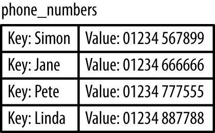
A dictionary stores key/value pairs in such a way that you can use the key to retrieve that value very efficiently and without having to search the whole dictionary.
To create a dictionary, you use the {} notation:
>>>phone_numbers={'Simon':'01234 567899','Jane':'01234 666666'}
In this example, the keys of the dictionary are strings, but they do not have to be; they could be numbers or in fact any data type, although strings are most commonly used.
The values can also be of any data type, including other dictionaries or lists. The following example creates one dictionary (a) and then uses it as a value in a second dictionary (b):
>>>a={'key1':'value1','key2':2}>>>a{'key2':2,'key1':'value1'}>>>b={'b_key1':a}>>>b{'b_key1':{'key2':2,'key1':'value1'}}
When you display the contents of a dictionary, you will notice that the order of the items in the dictionary may not match the order in which they were specified when the dictionary was created and initialized with some contents:
>>>phone_numbers={'Simon':'01234 567899','Jane':'01234 666666'}>>>phone_numbers{'Jane':'01234 666666','Simon':'01234 567899'}
Unlike lists, dictionaries have no concept of keeping items in order. Because of the way they are represented internally, the order of a dictionary’s contents will be—for all intents and purposes—random.
The reason the order appears to be random is that the underlying data structure is a hash table. Hash tables use a hashing function to decide where to store the value; the hashing function calculates a numeric equivalent to any object.
You can find out more about hash tables at Wikipedia.
Use the Python [] notation. Use the key of the entry to which you need access inside the brackets:
>>>phone_numbers={'Simon':'01234 567899','Jane':'01234 666666'}>>>phone_numbers['Simon']'01234 567899'>>>phone_numbers['Jane']'01234 666666'
The lookup process is in one direction only, from key to value.
If you use a key that is not present in the dictionary, you will get a key error. For example:
{'b_key1':{'key2':2,'key1':'value1'}}>>>phone_numbers={'Simon':'01234 567899','Jane':'01234 666666'}>>>phone_numbers['Phil']Traceback(mostrecentcalllast):File"<stdin>",line1,in<module>KeyError:'Phil'>>>
As well as using the [] notation to read values from a dictionary, you can also use it to add new values or overwrite existing ones.
The following example adds a new entry to the dictionary with a key of Pete and a value of 01234 777555:
>>>phone_numbers['Pete']='01234 777555'>>>phone_numbers['Pete']'01234 777555'
If the key is not in use in the dictionary, a new entry is automatically added. If the key is already present, then whatever value was there before will be overwritten by the new value.
This is in contrast to trying to read a value from the dictionary, where an unknown key will cause an error.
All the recipes between Recipes 6.12 and 6.15 involve the use of dictionaries.
For information on handling errors, see Recipe 7.10.
Use the pop command, specifying the key for the item that you want to remove:
>>>phone_numbers={'Simon':'01234 567899','Jane':'01234 666666'}>>>phone_numbers.pop('Jane')'01234 666666'>>>phone_numbers{'Simon':'01234 567899'}
The pop command returns the value of the item removed from the dictionary.
Use the for command to iterate over the keys of the dictionary:
>>>phone_numbers={'Simon':'01234 567899','Jane':'01234 666666'}>>>fornameinphone_numbers:...(name)...JaneSimon
There are a couple of other techniques that you can use to iterate over a dictionary. The following form can be useful if you need access to the values as well as the keys:
>>>phone_numbers={'Simon':'01234 567899','Jane':'01234 666666'}>>>forname,numinphone_numbers.items():...(name+" "+num)...Jane01234666666Simon01234567899
In this chapter, you will explore some of the more advanced concepts in the Python language—in particular, object-oriented Python, reading and writing files, handling exceptions, using modules, and Internet programming.
Apply a format string to the number. For example:
>>>x=1.2345678>>>"x={:.2f}".format(x)'x=1.23'>>>
The formatting string can contain a mixture of regular text and markers delimited by { and }. The parameters to the format function (there can be as many as you like) will be substituted in place of the marker, according to the format specifier.
In the preceding example, the format specifier is :.2f, which means that the number will be specified with two digits after the decimal place and is a float f.
If you wanted the number to be formatted so that the total length of the number is always seven digits (or padding spaces), then you would add another number before the decimal place like this:
>>>"x={:7.2f}".format(x)'x= 1.23'>>>
In this case, since the number is only three digits long, there are four spaces of padding before the 1. If you wanted the padding to take the form of leading zeros, you would use:
>>> "x={:07.2f}".format(x)
'x=0001.23'
>>>
A more complicated example might be to display the temperature in both degrees Celsius and degrees Fahrenheit, as shown here:
>>>c=20.5>>>"Temperature {:5.2f} deg C, {:5.2f} deg F.".format(c,c*9/5+32)'Temperature 20.50 deg C, 68.90 deg F.'>>>
Apply format string to the date object.
For example:
>>>fromdatetimeimportdatetime>>>d=datetime.now()>>>"{:%Y-%m-%d%H:%M:%S}".format(d)'2015-12-09 16:00:45'>>>
The Python formatting language includes some special symbols for formatting date. %Y, %m, and %d correspond to year, month, and day numbers, respectively.
Other symbols useful for formatting the date are %B, which supplies the full name of the month and %Y, which gives the year in four digit format, as shown here:
>>> "{:%d %B %Y}".format(d)
'09 December 2015'
See Recipe 7.1 for formatting of numbers.
Formatting in Python actually involves a whole formatting language. You will find full details of this at http://strftime.org/.
Return a Python tuple and use the multiple variable assignment syntax. A tuple is a Python data structure that’s a little like a list, except that tuples are enclosed in parentheses rather than brackets. They are also of fixed size.
For example, you could have a function that converts a temperature in Kelvin into both Fahrenheit and Celsius. You can arrange for this function to return the temperature in both these units by separating the multiple return values by commas:
>>>defcalculate_temperatures(kelvin):...celsius=kelvin-273...fahrenheit=celsius*9/5+32...returncelsius,fahrenheit...>>>c,f=calculate_temperatures(340)>>>>>>(c)67>>>(f)152.6
When you call the function, you just provide the same number of variables before the = and each of the return values will be assigned to the variables in the same position.
Sometimes when you just have one or two values to return, this is the right way to return multiple values. However, if the data is complex, you might find that the solution is neater if you use Python’s object-oriented features and define a class that contains the data. That way, you can return an instance of the class rather than a tuple.
See Recipe 7.4 for information on defining classes.
Define a class and provide it with the member variables you need.
The following example defines a class to represent an address book entry:
classPerson:'''This class represents a person object'''def__init__(self,name,tel):self.name=nameself.tel=tel
The first line inside the class definition uses the triple quotes to denote a documentation string. This should explain the purpose of the class. Although entirely optional, adding a documentation string to a class allows others to see what the class does. This is particularly useful if the class is made available for others to use.
Doc strings are not like normal comments because, although they are not active lines of code, they do get associated with the class, so, at any time, you can read the doc string for a class by using the following command:
Person.__doc__
Inside the class definition is the constructor method, which will be called automatically whenever you create a new instance of the class. A class is like a template, so in defining a class called Person, we do not create any actual Person objects until later:
def__init__(self,name,tel):self.name=nameself.tel=tel
The constructor method must be named as shown with double underscores on either side of the word init.
One way in which Python differs from most object-oriented languages is that you have to include the special variable self as a parameter to all the methods that you define within the class. This is a reference to, in this case, the newly created instance. The variable self is the same concept as the special variable this that you find in Java and some other languages.
The code in this method transfers parameters that were supplied to it into member variables. The member variables do not need to be declared in advance, but do need to be prefixed by self..
So the following line:
self.name=name
creates a variable called name that’s accessible to every member of the class Person and initializes it with the value passed into the call to create an instance, which looks like this:
p=Person("Simon","1234567")
We can then check that our new Person object, p, has a name of "Simon" by typing the following:
>>>p.nameSimon
In a complex program, it is good practice to put each class in its own file with a filename that matches the class name. This also makes it easy to convert the class into a module (see Recipe 7.11).
See Recipe 7.5 for information on defining methods.
The following example shows how you can include a method within a class definition:
classPerson:'''This class represents a person object'''def__init__(self,first_name,surname,tel):self.first_name=first_nameself.surname=surnameself.tel=teldeffull_name(self):returnself.first_name+" "+self.surname
The full_name method concatenates the first name and surname attributes of the person, with a space in between.
You can think of methods as just functions that are tied to a specific class and may or may not use member variables of that class in their processing. So, as with a function, you can write whatever code you like in a method and also have one method call another.
If one method calls another within the same class, the call to the method has to be prefixed with self.
See Recipe 7.4 for information on defining a class.
Use inheritance to create a subclass of an existing class and add new member variables and methods.
By default, all new classes that you create are subclasses of object. You can change this by specifying the class you want to use as a superclass in parentheses after the class name in a class definition. The following example defines a class (Employee) as a subclass of Person and adds a new member variable (salary) and an extra method (give_raise):
classEmployee(Person):def__init__(self,first_name,surname,tel,salary):super().__init__(first_name,surname,tel)self.salary=salarydefgive_raise(self,amount):self.salary=self.salary+amount
Note that the preceding example is for Python 3. For Python 2, you can’t use super the same way. Instead, you must write:
classEmployee(Person):def__init__(self,first_name,surname,tel,salary):Person.__init__(self,first_name,surname,tel)self.salary=salarydefgive_raise(self,amount):self.salary=self.salary+amount
See Recipe 7.4 for information on defining a class.
The Python inheritance mechanism is actually very powerful and supports multiple inheritance, where a subclass inherits from more than one superclass. For more on multiple inheritance, see the official documentation for Python.
Once you have opened the file, you can make as many writes to it as you like before you close the file. Note that it is important to use close because although each write should update the file immediately, it may be buffered in memory and data could be lost. It could also leave the file locked so that other programs can’t open it.
The open method takes two parameters. The first is the path to the file to be written. This can be relative to the current working directory, or if it starts with a /, an absolute path.
The second parameter is the mode in which the file should be opened. To overwrite an existing file or create the file with the name specified if it doesn’t exist, just use w. Table 7-1 shows the full list of file mode characters. You can combine these using +. So to open a file in read and binary mode, you would use:
>>>f=open('test.txt','r+b')
| Mode | Description |
|---|---|
|
r |
Read |
|
w |
Write |
|
a |
Append - to the end of an existing file rather than overwriting |
|
b |
Binary mode |
|
t |
Text mode (default) |
|
+ |
A shortcut for r+w |
Binary mode allows you to read or write binary streams of data, such as images, rather than text.
To read the contents of a file, see Recipe 7.8. For more information on handling exceptions, see Recipe 7.10.
You can also read text files one line at a time using the method readline.
The preceding example will throw an exception if the file does not exist or is not readable for some other reason. You can handle this by enclosing the code in a try/except construction like this:
try:f=open('test.txt')s=f.read()f.close()exceptIOError:("Cannot open the file")
To write things to a file and for a list of file open modes, see Recipe 7.7.
For more information on handling exceptions, see Recipe 7.10.
Use the Python pickling feature to dump the data structure to file in a format that can be automatically read back into memory as an equivalent data structure later on.
The following example saves a complex list structure to file:
>>>importpickle>>>mylist=['some text',123,[4,5,True]]>>>f=open('mylist.pickle','w')>>>pickle.dump(mylist,f)>>>f.close()
To unpickle the contents of the file into a new list, use the following:
>>>f=open('mylist.pickle')>>>other_array=pickle.load(f)>>>f.close()>>>other_array['some text',123,[4,5,True]]
Pickling will work on pretty much any data structure you can throw at it. It does not need to be a list.
The file is saved in a text format that is sort of human-readable, but you will not normally need to look at or edit the text file.
To write things to a file and for a list of file open modes, see Recipe 7.7.
Use Python’s try/except construct.
The following example, taken from Recipe 7.8, catches any problems in opening a file:
try:f=open('test.txt')s=f.read()f.close()exceptIOError:("Cannot open the file")
Because you wrapped the potentially error-prone commands to open the file in a try/except construction, any error that occurs will be captured before it displays any error message allowing you to handle it in your own way. In this case, that means displaying the friendly message "Cannot open the file".
A common situation where runtime exceptions can occur, in addition to during file access, is when you are accessing a list and the index you are using is outside the bounds of the list. For example, this happens if you try to access the fifth (index 4) element of a three-element list:
>>>list=[1,2,3]>>>list[4]Traceback(mostrecentcalllast):File"<stdin>",line1,in<module>IndexError:listindexoutofrange
Errors and exceptions are arranged in a hierarchy, and you can be as specific or general as you like when catching the exceptions.
Exception is pretty near the top of that tree and will catch almost any exception. You can also have separate except sections for catching different types of exception and handling, each in a different way. If you do not specify any exception class, all exceptions will be caught.
Python also allows you to have else and finally clauses in your error handling:
list=[1,2,3]try:list[8]except:("out of range")else:("in range")finally:("always do this")
The else clause will be run if there is no exception, and the finally clause will be run whether there is an exception or not.
Whenever an exception occurs, you can get more information about it by using the exception object, which is available only if you use the as keyword, as shown in the following example:
>>>list=[1,2,3]>>>try:...list[8]...exceptExceptionase:...("out of range")...(e)...outofrangelistindexoutofrange>>>
This allows you to handle the error in your own way, but also keep hold of the original error message.
Python documentation for Python exception class hierarchy.
Use the import command:
importrandom
There is a very large number of modules (sometimes called libraries) available for Python. Many are included with Python as part of the standard library and others can be downloaded and installed into Python.
Standard Python libraries include modules for random numbers, database access, various Internet protocols, object serialization, and many more.
One consequence of having so many modules is that there is the potential for conflict—for example, if two modules have a function of the same name. To avoid such conflicts, when importing a module, you can specify how much of the module is accessible.
For example, if you just use a command like this:
importrandom
there is no possibility of any conflicts because you will only be able to access any functions or variables in the module by prefixing them with random.. (Incidentally, you’ll be meeting the random package in the next recipe.)
If, on the other hand, you use the following command, everything in the module will be accessible without your having to put anything in front of it. Unless you know what all the functions are in all the modules you are using, there is a much greater chance of conflict.
fromrandomimport*
In between these two extremes, you can explicitly specify the components of a module that you need within a program so that they can be conveniently used without any prefix.
For example:
>>>fromrandomimportrandint>>>(randint(1,6))2>>>
A third option is to use the as keyword to provide a more convenient or meaningful name for the module when referencing it.
>>>importrandomasR>>>R.randint(1,6)
For a definitive list of the modules included with Python, see http://docs.python.org/2/library/.
Use the random library:
>>>importrandom>>>random.randint(1,6)2>>>random.randint(1,6)6>>>random.randint(1,6)5
The number generated will be between the two arguments (inclusive)—in this case, simulating a gaming dice.
The numbers generated are not truly random, but are what is known as a pseudorandom number sequence; that is, they are a long sequence of numbers that, when taken in a large enough quantity, show what statisticians call a random distribution. For games, this is perfectly good enough, but if you were generating lottery numbers, you would need to look at special randomizing hardware. Computers are just plain bad at being random; it’s not really in their nature.
A common use of random numbers is to select something at random from a list. You can do this by generating an index position and using that, but there is also a command in the random module specifically for this. Try the following example:
>>>importrandom>>>random.choice(['a','b','c'])'a'>>>random.choice(['a','b','c'])'b'>>>random.choice(['a','b','c'])'a'
See the official reference for the random package for more information on this.
If you are using Python 3 rather than Python 2, then you will need to change your example to:
importurllib.requestresponse=urllib.request.urlopen('http://python.org/')contents=response.read()(contents)
Having read the HTML, you are then likely to want to search it and extract the parts of the text that you really want. For this, you will need to use the string manipulation functions (see Recipes 5.14 and 5.15).
For more Internet-related examples using Python, see Chapter 15.
Import sys and use its argv property, as shown in the following example. This returns an array, the first element of which is the name of the program. The other elements are any parameters (separated by spaces) that were typed on the command line after the program name.
importsysfor(i,value)inenumerate(sys.argv):("arg:%d%s"%(i,value))
Running the program from the command line, with some parameters after it, results in the following output:
$ python cmd_line.py a b c
arg: 0 cmd_line.py
arg: 1 a
arg: 2 b
arg: 3 c
Being able to specify command-line arguments can be useful for automating the running of Python programs, either at startup (Recipe 3.21) or on a timed basis (Recipe 3.23).
For basic information on running Python from the command line, see Recipe 5.4.
In printing out argv, we used list enumerations (Recipe 6.8).
Use the system command.
For example, to delete a file called myfile.txt in the directory from which you started Python, you could do the following:
importosos.system("rm myfile.txt")
Sometimes rather than just execute a command blindly as in the example above, you need to capture the response of the command. Let’s say you wanted to use the 'hostname' command to find the IP address (see Recipe 2.2) of the Raspberry Pi. In this case, you can use the check_output function in the subprocess library.
importsubprocessip=subprocess.check_output(['hostname','-I'])
In this case, the variable ip will contain the IP address of the Raspberry Pi. Unlike system, check_output requires the command itself and any parameters to be supplied as separate elements of an array.
For documentation on the OS library, see http://www.pythonforbeginners.com/os/pythons-os-module.
For more information on the subprocess library, see https://docs.python.org/3/library/subprocess.html.
In Recipe 14.4, you will find an example using subprocess to display the IP address, hostname, and time of your Raspberry Pi on an LCD screen.
Python has a library for the Simple Mail Transfer Protocol (SMTP) that you can use to send emails:
importsmtplibGMAIL_USER='your_name@gmail.com'GMAIL_PASS='your_password'SMTP_SERVER='smtp.gmail.com'SMTP_PORT=587defsend_email(recipient,subject,text):smtpserver=smtplib.SMTP(SMTP_SERVER,SMTP_PORT)smtpserver.ehlo()smtpserver.starttls()smtpserver.ehlosmtpserver.login(GMAIL_USER,GMAIL_PASS)header='To:'+recipient+'\n'+'From: '+GMAIL_USERheader=header+'\n'+'Subject:'+subject+'\n'msg=header+'\n'+text+'\n\n'smtpserver.sendmail(GMAIL_USER,recipient,msg)smtpserver.close()send_email('destination_email_address','sub','this is text')
To use this example to send an email to an address of your choice, first change the variables GMAIL_USER and GMAIL_PASS to match your email credentials. If you are not using Gmail, then you will also need to change the values of the SMTP_SERVER and possibly SMTP_PORT.
You also need to change the destination email address in the last line.
The send_email message simplifies the use of the smtplib library into a single function that you can reuse in your projects.
Being able to send emails from Python opens up all sorts of project opportunities. For example, you could use a sensor such as the PIR sensor to send an email when movement is detected.
For a similar example that uses the IFTTT web service to send emails, see Recipe 15.3.
For performing HTTP requests from the Raspberry Pi, see Recipe 7.13.
For more information on the smtplib, see http://docs.python.org/2/library/smtplib.html.
For a whole load of Internet-related recipes, see Chapter 15.
Use the bottle Python library to run a pure Python web server that will respond to HTTP requests.
To install bottle, use the following command:
sudo apt-get install python-bottle
The following Python program (called bottle_test in the book resources) simply serves up a message displaying what time the Pi thinks it is. Figure 7-1 shows the page you see if you connect to the Raspberry Pi from a browser anywhere on your network:
frombottleimportroute,run,templatefromdatetimeimportdatetime@route('/')defindex(name='time'):dt=datetime.now()time="{:%Y-%m-%d%H:%M:%S}".format(dt)returntemplate('<b>Pi thinks the date/time is: {{t}}</b>',t=time)run(host='0.0.0.0',port=80)
To start the program, you need to run it with superuser privileges:
$ sudo python bottle_test.py
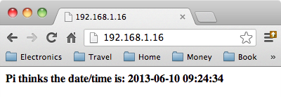
This example requires a little explanation.
After the import commands, the @route command links the URL path / with the handler function that follows it.
That handler function formats the date and time and then returns a string of the HTML to be rendered by the browser. In this case, it uses a template into which values can be substituted.
The final run line actually starts the web serving process. Port 80 is the default port for web serving, so if you wish to use a different port, then you need to add the port number with a : after the server address.
You can define as many routes and handlers as you like within the program.
bottle is perfect for small, simple web server projects, and because it’s written in Python, it’s very easy to write a handler function to control hardware in response to the user interacting with the page in a browser. You will find other examples using bottle in Chapter 15.
For more information, see the bottle project documentation.
For more on formatting dates and times in Python, see Recipe 7.2.
For a whole load of Internet-related recipes, see Chapter 15.
Use the Python thread library.
The following example, which you can download from the Downloads section of the Raspberry Pi Cookbook website, sets a thread running that will interrupt the counting of the main thread.
importthread,time,randomdefannoy(message):whileTrue:time.sleep(random.randint(1,3))(message)thread.start_new_thread(annoy,('BOO !!',))x=0whileTrue:(x)x+=1time.sleep(1)
The output on the console will look something like this:
$ python thread_test.py
0
1
BOO !!
2
BOO !!
3
4
5
BOO !!
6
7
8
When you start a new thread of execution using the Python thread library, you must specify a function that is to be run as that thread. In this example, the function is called annoy and it contains a loop that will continue indefinitely printing out a message after a random interval of between 1 and 3 seconds.
To start the thread, the start_new_thread function in the thread module is called. This function expects two parameters: the first is the name of the function to run (in this case annoy) and the second is a tuple that contains any parameters that are to be passed to the function (in this case 'BOO !!').
You can see that the main thread that is just happily counting will be interrupted every few seconds by the thread running in the annoy function.
Threads like these are also sometimes called lightweight processes because they are similar in effect to having more than one program or process running at the same time. They do, however, have the advantage that threads running in the same program have access to the same variables, and when the main thread of the program exits, so do any threads that are started in it.
For a good introduction to threading in Python, see http://www.tutorialspoint.com/python/python_multithreading.htm.
Use the sleep function in the time library as illustrated in the following code example that you can find with the downloads for the book called sleep_test.py.
importtimex=0whileTrue:(x)time.sleep(1)x+=1
The main loop of the program will delay for a second before printing the next number.
The function time.sleep takes a number of seconds as its parameter. But if you want shorter delays, you can specify decimals. For example, to delay for a millisecond, you would use time.sleep(0.001).
Its a good idea to put a short delay in any loop that continues indefinitely, or even just continues for more than a fraction of a second, because when sleep is being called, the processor is freed up to allow other processes to do some work.
For an interesting discussion of how time.sleep can reduce the CPU load of your Python program, see http://raspberrypi.stackexchange.com/questions/8077/how-can-i-lower-the-usage-of-cpu-for-this-python-program.
Use the Python interface that comes with Minecraft Pi edition to interact with Minecraft Pi while it is running.
Although you can switch back and forth between an LXTerminal session and the Minecraft game, the game will pause each time the window loses focus, so it is a lot easier to connect to the Raspberry Pi by using SSH on a second computer (Recipe 2.7). This has the added benefit that you get to see the Python script in action, live in the game.
The following example, which you can download from the Downloads section of the Raspberry Pi Cookbook website, builds a staircase at your current location (Figure 7-2):
frommcpiimportminecraft,blockmc=minecraft.Minecraft.create()mc.postToChat("Lets Build a Staircase!")x,y,z=mc.player.getPos()forxyinrange(1,50):mc.setBlock(x+xy,y+xy,z,block.STONE)
The Python library comes pre-installed in Raspbian, so if it’s not there, you should probably update your system (Recipe 1.5).
After the library imports, the variable mc is assigned to a new instance of the Minecraft class.
The postToChat method sends a message to the player’s screen telling him or her that the staircase is about to be built.
The variables x, y, and z are bound to the player’s position and then the for loop increments both the x and y (y is height) repeatedly to build the staircase using the setBlock method (Figure 7-2).

The mcpi library does not just allow you to post to chat, find the player’s location, and place a block, it also provides a whole load of other methods that allow you to:
There is no definitive documentation for the class other than this useful blog post.
For more information on the Minecraft Pi Edition, see Recipe 4.7.
To learn about running a Minecraft server on a Raspberry Pi, see Recipe 4.8.
Computer vision (CV) allows your Raspberry Pi to see things. In practical terms, this means that your Raspberry Pi can analyze an image, looking for items of interest and even recognizing faces and text.
If you link this with a camera to supply the images, all sorts of possibilities open up.
To install SimpleCV, first install the prerequisite packages using these commands:
$ sudo apt-get update
$ sudo apt-get install ipython python-opencv python-scipy
$ sudo apt-get install python-numpy python-setuptools python-pip
$ sudo pip install svgwrite
Then install SimpleCV itself using the command:
$ sudo pip install https://github.com/sightmachine/SimpleCV/zipball/master
Once installation is complete, you can check that everything worked by running this command:
$ simplecv
+-----------------------------------------------------------+
 SimpleCV 1.3.0 [interactive shell] - http://simplecv.org
+-----------------------------------------------------------+
Commands:
    "exit()" or press "Ctrl+ D" to exit the shell
    "clear()" to clear the shell screen
    "tutorial()" to begin the SimpleCV interactive tutorial
    "example()" gives a list of examples you can run
    "forums()" will launch a web browser for the help forums
    "walkthrough()" will launch a web browser with a walkthrough
This will open the SimpleCV console. This is a Python console, with extra features for SimpleCV.
SimpleCV is a Python wrapper around the OpenCV computer vision software. SimpleCV, as the name suggests, simplifies the use of OpenCV. If you want to unleash the full power of OpenCV, take a look at http://opencv.org/.
Computer vision is both processor- and memory-intensive, so although SimpleCV and OpenCV will work on an older Raspberry Pi, it can be frustratingly slow on anything earlier than a Raspberry Pi 3 or 2.
For information on OpenCV, see http://opencv.org/.
The home page for the SimpleCV project is http://simplecv.org.
The first recipe in this chapter to use SimpleCV is Recipe 8.4 and you will find useful details for getting started with SimpleCV there.
Use a USB webcam that is compatible with the Raspberry Pi (see http://elinux.org/RPi_USB_Webcams). Choose a good quality camera, and if you are working on a project where you need the camera close to the subject, select one that has a manual focus option. For getting really close to the subject, a low-cost USB endoscope can be useful.
Depending on your CV project, you may wish to set up a well-lighted area for your CV project. Figure 8-1 shows a simple light box made from a translucent plastic storage box illuminated from the sides and top to give even lighting. The webcam is attached to a hole in the top of the box. This arrangement is used in Recipe 8.4.

You can also buy commercial light tents designed for photography that work well.
You may need a little trial and error to get your system brightly and evenly illuminated. Shadows can be particularly problematic.
You can test out your USB camera from the SimpleCV console. Start SimpleCV and then enter the commands shown below in bold:
SimpleCV:1> c = Camera()
VIDIOC_QUERYMENU: Invalid argument
VIDIOC_QUERYMENU: Invalid argument
VIDIOC_QUERYMENU: Invalid argument
VIDIOC_QUERYMENU: Invalid argument
VIDIOC_QUERYMENU: Invalid argument
VIDIOC_QUERYMENU: Invalid argument
VIDIOC_QUERYMENU: Invalid argument

SimpleCV:2> i = c.getImage()
SimpleCV:3> i
SimpleCV:3: <SimpleCV.Image Object size:(640, 480), filename: (None),
at memory location: (0x2381af8)>
SimpleCV:4> i.show()
Don’t worry about the Invalid argument messages.
When you issue the command i.show(), a second window opens showing the image just captured from the camera.
Although you can use the Raspberry Pi Camera module (Recipe 8.3) with SimpleCV, it has a very short lead to the Raspberry Pi and you will probably find that you prefer working with a high-quality webcam.
To use a Raspberry Pi Camera Module with SimpleCV, see Recipe 8.3.
The Raspberry Pi Camera Module does not automatically show up as a camera device. The easiest way to make the module work with SimpleCV is to use the picamera Python module to capture an image with the camera.
The following code fragment will use picamera to capture an image, save it to a temporary file, and then load it as an Image suitable for use with SimpleCV.
import picamera
from SimpleCV import *

def get_camera_image():
    with picamera.PiCamera() as camera:
        camera.capture('tmp.jpg')
    return Image('tmp.jpg')
In Recipe 8.4, the program assumes a USB webcam. A second version of the program using the function above for the Raspberry Pi camera module is also provided in the file coin_count_pi_cam.py.
It may seem inefficient to write a file each time an image is captured, and indeed it is, but any processing that you apply to the image with SimpleCV on a Raspberry Pi is likely to take a lot longer than the time taken to load and save the image.
The picamera module allows you to set various features of the camera. Most usefully, you can control the resolution, automatic exposure, and white-balance adjustments, which can make it easier to get consistent results with CV.
The native resolution of the camera is 2592×1944, which will make for pretty slow image processing, so you may want to set the resolution to something closer to 1024×768 and turn off auto-white balance. The get_camera_image function can be modified to include these settings, as shown here:
import picamera
from SimpleCV import *

def get_camera_image():
    with picamera.PiCamera() as camera:
        camera.resolution = (1024, 768)
        camera.awb_mode = 'off'
        camera.capture('tmp.jpg')
    return Image('tmp.jpg')
See Recipe 1.14 for information on installing the Raspberry Pi camera module.
For information on the picamera Python module, see http://picamera.readthedocs.org/.
To use a USB camera with SimpleCV, see Recipe 8.2.
Use SimpleCV and its findCircle function to provide a real-time count of the number of coins placed under the webcam.
This is one use of CV where you really need good lighting and a camera fixed in position. I used the setup shown in Figure 8-1.
Before writing a Python program that will simply tell you the number of coins your Raspberry Pi can see, you need to experiment with the SimpleCV console to get the parameters for circle recognition right.
Start SimpleCV by using the command simplecv and then enter the commands below to start the camera, capture an image, and then display it in a separate window.
SimpleCV:1> c = Camera()
SimpleCV:2> i = c.getImage()
SimpleCV:3> i.show()
This should open up an image of your coins that looks something like Figure 8-2.

Circle detection needs the image to be inverted, or you can use a black background. To invert the image and then display it, run the commands below:
SimpleCV:4> i2 = i.invert()
SimpleCV:5> i2.show()
This command makes an inverted copy of i that looks like Figure 8-3.

Your image is now prepared, so the next step is to have SimpleCV search for circles using the findCircle command. This command takes three parameters that you will need to tune to prevent misidentification. The parameters are:
cannyThis is the threshold for edge detection. In CV terms, an edge is the line between significant changes in the image pixel colors. The default for this parameter is 100, and if you decrease this value, you will find more edges. This might not result in more circles being found because those extra edges might corrupt the good circle shapes. In the case of a coin, the edges could be writing or graphics on the coin.
threshHaving found edges, the circle detection then needs to decide which are strong enough to represent the circles. Decreasing this value will result in more circles being found.
distanceThis parameter sets the required gap (in pixels) between adjacent circles.
Run the following command to find some circles:
SimpleCV:6> coins = i2.findCircle(canny=100, thresh=70, distance=15)
SimpleCV:7> coins
 SimpleCV.Features.Detection.Circle at (237,297),
 SimpleCV.Features.Detection.Circle at (307,323),
 SimpleCV.Features.Detection.Circle at (373,305),
 SimpleCV.Features.Detection.Circle at (305,261),
 SimpleCV.Features.Detection.Circle at (385,253),
 SimpleCV.Features.Detection.Circle at (243,231),
 SimpleCV.Features.Detection.Circle at (307,383),
 SimpleCV.Features.Detection.Circle at (407,371),
 SimpleCV.Features.Detection.Circle at (235,373)]
If you don’t get any coins back, try decreasing the canny and thresh parameters. If you get too many, then increase thresh. We can check that SimpleCV is actually finding coins by superimposing the coin circles onto the original image using the following command.
SimpleCV:8> coins.draw(width=4)
SimpleCV:9> coins.show()
This will show the circles superimposed on the actual coins (Figure 8-4).
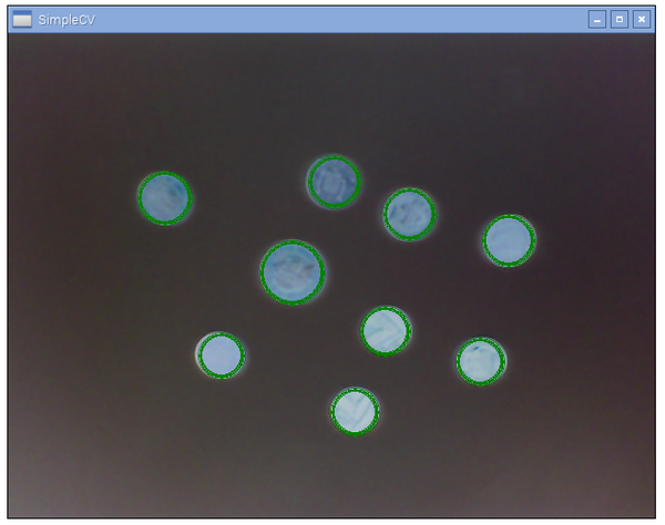
Try moving the coins around and adding and removing coins before capturing another photo and repeating the steps above to make sure things are reliable. You can tweak the parameters until you get the results you want.
We can bundle the commands that we used in the SimpleCV console into a Python program that will (as fast as the Raspberry Pi can) print out the number of coins detected. The program can be found with the other downloads for the book in the file coin_count.py.
fromSimpleCVimport*c=Camera()whileTrue:i=c.getImage().invert()coins=i.findCircle(canny=100,thresh=70,distance=1)(len(coins))
After importing the SimpleCV library, the commands are the same as the ones you typed into the console. The only difference is that rather than displaying the coins, the len function is used to display the count.
$ sudo python count_coins.py
9
9
9
10
10
Try adding a coin and moving the coins around to see how well the project works.
After the initial delay while the library loads and the camera is set up, I found I could get about two “countings” per second using a Raspberry Pi B+. Using a Raspberry Pi 2, this increased to about five readings per second.
Although not something that you would want to put into a vending machine, it would be an interesting project to use the diameter of the coins to identify their monetary value and add up the value of the coins on the table.
You can access the diameter by using the diameter method on one of the coins like this:
SimpleCV:10> coins[0].diameter() SimpleCV:11> 60
For information on installing SimpleCV, see Recipe 8.1.
For information on setting up a camera, see Recipe 8.2.
Use the Haar-like feature detection in SimpleCV to analyze an image and pick out the faces.
If you have not already done so, install SimpleCV (see Recipe 8.1). Open the SimpleCV console and load an image containing faces. You will find a suitable file with the downloads for the book called faces.jpg. Then run the following commands:
SimpleCV:1> i=Image("faces.jpg")
SimpleCV:2> faces = i.findHaarFeatures('face.xml', min_neighbors=5)
SimpleCV:3> faces.draw(width=4)
SimpleCV:4> i.show()
This opens the image viewing window with the faces marked with rectangles, as shown in Figure 8-5.
As well as interfacing with a camera, you can also load existing files into SimpleCV. In the previous example, the image i is loaded from the file faces.jpg. The method findHaarFeatures has one mandatory file, which is the type of feature that is being searched for. These features are called haar features and are described by an XML file. SimpleCV comes preloaded with some of these files, but you can also find more specific haar files on the Internet.
The second parameter used in this example (min_neighbors) will tune the haar function. Decreasing min_neighbors increases the number of false positives. When you see the false positives, they often have a face-ish element to them (mouth, nose, and eyes).
There are many built-in haar features. You can list them all by using the command:
SimpleCV:5> i.listHaarFeature() SimpleCV:4> fullbody.xml', 'face4.xml', 'face.xml', 'upper_body.xml', 'right_ear.xml', 'eye.xml', 'lower_body.xml', 'two_eyes_small.xml', 'nose.xml', 'face2.xml', 'lefteye.xml', 'right_eye.xml', 'two_eyes_big.xml', 'face3.xml', 'mouth.xml', 'glasses.xml', 'profile.xml', 'left_ear.xml', 'left_eye2.xml', 'upper_body2.xml', 'right_eye2.xml', 'face_cv2.xml'
As you can see, they are all associated with parts of the body.
Finding haar features takes a few seconds, even on a Raspberry Pi 3.

For information on installing SimpleCV, see Recipe 8.1.
For information on setting up a camera, see Recipe 8.2.
For a whole load of interesting Haar files, take a look at https://github.com/Itseez/opencv/tree/master/data/haarcascades.
Use SimpleCV to detect changes between successive frames from the camera.
The program below compares each captured image with the previous image. It then detects any blobs (areas of similar color) in the difference image and if there are any larger than MIN_BLOB_SIZE, it prints out a message saying that movement was detected.
fromSimpleCVimport*MIN_BLOB_SIZE=1000c=Camera()old_image=c.getImage()whileTrue:new_image=c.getImage()diff=new_image-old_imageblobs=diff.findBlobs(minsize=MIN_BLOB_SIZE)ifblobs:("Movement detected")old_image=new_image
Successive frames of the image might look like Figures 8-6 and 8-7. When the first image is subtracted from the first, the resulting image will look like Figure 8-8. Running blob detection on it will result in the outlined blobs shown in Figure 8-9.


Using a Raspberry Pi 2, the motion detection program above will process about five frames per second.
For information on installing SimpleCV, see Recipe 8.1 . For information on setting up a camera, see Recipe 8.2.
An alternative way to detect movement is to use a Passive Infrared (PIR) sensor; see Recipe 12.9.
Use the tesseract Optical Character Recognition (OCR) software to extract text from the image.
To install tesseract, run the following commands:
$ sudo apt-get install python-distutils-extra tesseract-ocr tesseract-ocr-eng libopencv-dev libtesseract-dev libleptonica-dev python-all-dev swig libcv-dev python-opencv python-numpy python-setuptools build-essential subversion $ sudo apt-get install tesseract-ocr-eng tesseract-ocr-dev libleptonica-dev python-all-dev swig libcv-dev $ sudo svn checkout http://python-tesseract.googlecode.com/svn/python-tesseract-0.7.4/ $ cd python-tesseract-0.7.4 $ sudo python setup.py build $ sudo python setup.py install
To try out tesseract, you will need an image file that contains some text. You will find one called ocr_example.png with the downloads for the book.
To convert the image to text, run the command:
$ tesseract ocr_example.png found Tesseract Open Source OCR Engine v3.02 with Leptonica $ more found.txt The quick brown fox jumped over the lazy dogs back. $
The tesseract library will work with most image types, including PDF, PNG, and JPG files.
For more information on the tesseract library, see https://github.com/tesseract-ocr/tesseract/wiki/TrainingTesseract.
This chapter contains some basic recipes for setting up and using the Raspberry Pi’s general-purpose input/output (GPIO) connector. This connector allows you to connect all sorts of interesting electronics to your Raspberry Pi.
Be sure to check out the accompanying video for this recipe at http://razzpisampler.oreilly.com.
There have actually been three versions of the Raspberry Pi GPIO connector. Two 26-pin layouts for the original Raspberry Pi and one 40-pin layout that came in with the Raspberry Pi “+” models.
Figure 9-1 shows the GPIO pinout for revisions 1 and 2 of the original Raspberry Pi Model B. The quick way to distinguish the boards is knowing that if you have one of the very first revision 1 boards, it has a black audio socket. The revision 2 boards have a blue audio socket.
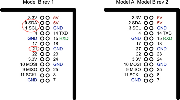
There were three changes to the GPIO connector between revision 1 and revision 2. These are highlighted in Figure 9-1. First, the I2C port was swapped. The two pins SDA and SCL are still SDA and SCL but use a different internal I2C interface. This means that if you’re using the pins as GPIO rather than I2C, then you will refer to them as 2 and 3 on a revision 2 board. Also, GPIO 21 was replaced by GPIO 27 on revision 2.
At the top of the connector, there are 3.3V and 5V power supplies. The GPIO uses 3.3V for all inputs and outputs. Any pin with a number next to it can act as a GPIO pin. Those that have another name after them also have some other special purpose, so 14 TXD and 15 RXD are the transmit and receive pins of the serial interface. SDA and SCL form the I2C interface, and MOSI, MISO, and SCKL from the SPI interface.
Figure 9-2 shows the current 40-pin layout, which is the same for all 40-pin GPIO Raspberry Pi models.
The top 26 pins are the same as the 26 pins of the original Raspberry Pi Model B revision 2. This allows the 40-pin Raspberry Pi models to use hardware and software designed for the earlier 26-pin Raspberry Pi designs. The extra pins of the 40-pin connector are made up of three useful extra GND connections and 9 GPIO pins. The ID_SD and ID_SC pins are intended for use in communicating with a special serial memory chip, which can be included on interface boards that conform to the Hardware At Top (HAT) standard and allows the Raspberry Pi to identify the board (see Discussion, next).
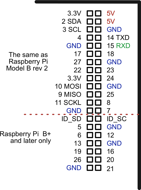
Working out which pin is which on a Raspberry Pi is quite error-prone if you rely on counting down the pin connector to find the pin you need. A better way of finding the right pin is to use a GPIO template like the Raspberry Leaf shown in Figure 9-3.
This paper template fits over the GPIO pins telling you which is which. Other GPIO templates include the Pi GPIO Reference Board.
The Hardware At Top standard is an interface standard that you can use with the Raspberry Pi 2, B+ and A+. This standard does not in any way stop you from just using GPIO pins directly; however, interface boards that conform to the HAT standard can call themselves HATs and differ from regular Raspberry Pi interface boards in that a HAT must contain a little Electrically Erasable Programmable Read-Only Memory (EEPROM) chip that is used to identify the HAT so that ultimately the Raspberry Pi can auto-install necessary software. At the time of writing, HATs have not quite met that level of sophistication, but the idea is a good one. The pins ID_SD and ID_SC are used to communicate with a HAT EEPROM.
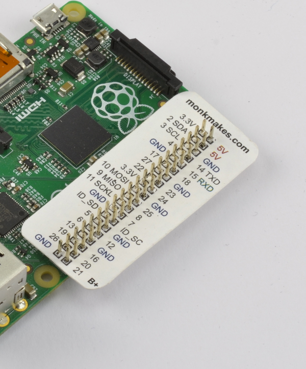
The Raspberry Pi GPIO connector only has digital inputs and outputs; it does not have the analog inputs found on some similar boards. You can get around this short-coming by using a separate ADC chip (Recipe 13.5) or using resistive sensors (Recipe 13.1).
For an example of a HAT, see the Sense HAT described in Recipe 9.16.
Obey these simple rules to reduce the risk of damaging your Raspberry Pi when using the GPIO connector:
Do not put more than 3.3V on any GPIO pin being used as an input.
Do not draw more than 16mA per output and keep the total for all outputs below 50mA in total for an older 26-pin Raspberry Pi, and below 100mA on a 40-pin Raspberry Pi.
When using LEDs, 3mA is enough to light a red LED reasonably brightly with a 470Ω series resistor.
Do not poke at the GPIO connector with a screwdriver or any metal object when the Pi is powered up.
Do not power the Pi with more than 5V.
Do not draw more than a total of 250mA from the 5V supply pins.
There is no doubt about it, the Raspberry Pi is a little fragile when it comes to adding external electronics. The newer Raspberry Pi models are a little more robust but still quite easy to break. Exercise caution and check what you have done before you power up the Raspberry Pi, or you run the risk of having to replace your Raspberry Pi.
Read this very good discussion of the Raspberry Pi’s GPIO output capabilities.
In the latest versions of Raspbian, enabling I2C is simply a matter of using the Raspberry Pi Configuration tool that you will find on the main menu under Preferences (Figure 9-4). Just check the box for I2C and click OK. You will be prompted to restart.

On older versions of Raspbian, the raspi-config tool does the same job.
Start raspi-config using the following command:
$ sudo raspi-config
Then select Advanced from the menu and scroll down to I2C (Figure 9-5).
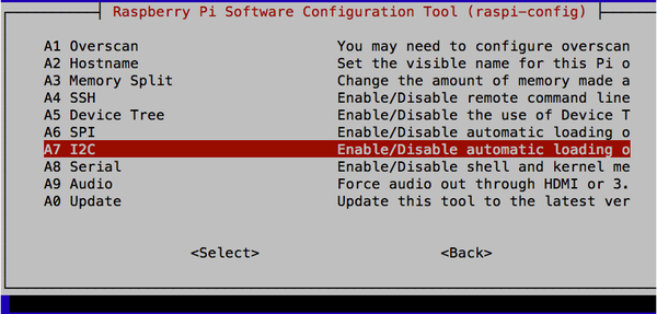
You will then be asked “Would you like the ARM I2C interface to be enabled?”, to which you should say “Yes.” You will also be asked if you want the I2C module loading at startup, to which you should also say “Yes.”
At this point, you will probably also want to install the Python I2C library by using the command:
$ sudo apt-get install python-smbus
You will then need to reboot the Raspberry Pi for the changes to take effect.
Using I2C modules is actually a really good way of interfacing with the Pi. It reduces the number of wires that you need to connect everything (to just four), and there are some really neat I2C modules available.
However, don’t forget to calculate the total of the current used by the I2C modules and make sure that it doesn’t exceed those specified in Recipe 9.2.
Figure 9-6 shows a selection of I2C modules available from Adafruit. Other suppliers, such as SparkFun, also have I2C devices. From left to right, there are LED matrix displays; a four-digit, seven-segment LED display; a 16-channel PWM/servo controller; and a real-time clock module.
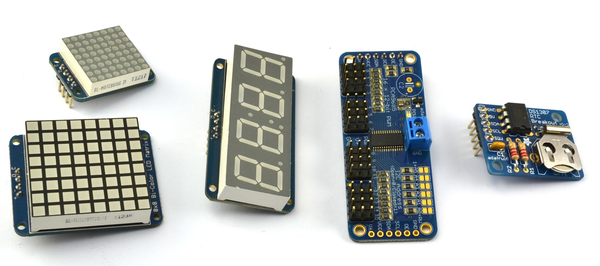
Other I2C modules include FM radio transmitters, ultrasonic rangefinders, OLED displays, and various types of sensors.
Install and use i2c-tools.
On newer distributions, you may find that i2c-tools is already installed.
From a Terminal window on your Pi, type the following commands to fetch and install the i2c-tools:
$ sudo apt-get install i2c-tools
Attach your I2C device to the Pi and run the command:
$ sudo i2cdetect -y 1
Note that if you are using a very old Raspberry Pi revision 1 board, you need to change 1 to 0 in the preceding line of code.
If I2C is available, you will see some output like that shown in Figure 9-7. This shows that two I2C addresses are in use—0x68 and 0x70.
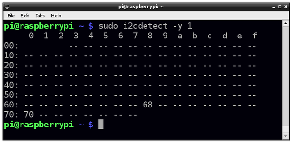
See some of the I2C recipes in this book, including Recipes 11.3, 14.1, 14.2, and 14.4.
For more information on installing with apt-get, see Recipe 3.16.
By default, Raspbian is not configured for the Raspberry Pi’s SPI interface to be enabled. To enable it, the procedure is almost the same as Recipe 9.3. Use the Raspberry Pi Configuration tool that you will find on the main menu under Preferences, or on older versions of Raspbian, use the raspi-config using the command:
$ sudo raspi-config
Then select Advanced, followed by SPI, and then Yes before rebooting your Raspberry Pi. After the reboot, SPI will be available.
SPI allows serial transfer of data between the Raspberry Pi and peripheral devices, such as analog-to-digital converter (ADC) and port expander chips, among other devices.
You may come across some examples of interfacing to SPI that do not use the SPI interface but instead use an approach called bit banging, where the RPi.GPIO library is used to interface with the four GPIO pins used by the SPI interface.
We use a SPI analog-to-digital converter chip in Recipe 13.5.
The library is pretty easy to use. Creating a connection uses the following syntax:
ser=serial.Serial(DEVICE,BAUD)
Where DEVICE is the device for the serial port (/dev/ttyAMA0) and BAUD is the baud rate as a number, not a string. For example:
ser=serial.Serial('/dev/ttyAMA0',9600)
Once a connection is established, you can send data over serial like this:
ser.write('some text')
Listening for a response normally involves a loop that reads and prints, as illustrated in this example:
whileTrue:(ser.read())
You will need to use this technique in recipes that connect hardware to the serial port, such as Recipe 12.10.
$ sudo apt-get install minicom
Once Minicom is installed, you can start a serial communications session with a serial device connected to the RXD and TXD pins of the GPIO connector by using this command:
$ minicom -b 9600 -o -D /dev/ttyAMA0
The parameter after -b is the baud rate, and after -D, the serial port. Remember to use the same baud rate as the one on the device you are communicating with.
This will start a Minicom session. One of the first things you want to do is turn on local echo so you can see the command that you are typing. To do this, press Ctrl-A and then Z; you’ll see the command list shown in Figure 9-8. Press E to turn on local echo.
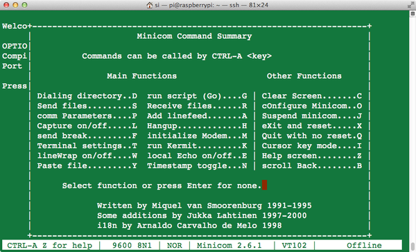
Now anything you type will be sent to the serial device, and all messages coming from the device will also be displayed.
Minicom is a great tool for checking out the messages coming from a serial device or making sure that it’s working.
Check out the Minicom documentation.
If you want to write a Python program to handle the serial communications, you will need the Python serial library (Recipe 9.6).
Use male-to-female jumper wires and a GPIO pin label template like the Raspberry Leaf (Figure 9-9).
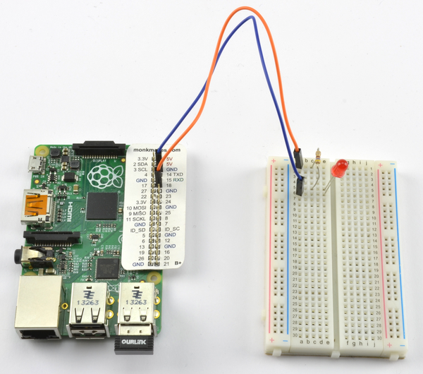
It’s not always easy to identify the pins you want on a bare Raspberry Pi board. You can greatly simplify this by printing out a template, like the Raspberry Leaf, to fit over the pins.
It is also useful to have a selection of male-to-male jumper wires for making connections from one part of the breadboard to another.
Female-to-female jumper wires are useful for connecting modules with male header pins directly to the Raspberry Pi, when no other components might warrant the use of a breadboard.
A good way of getting a breadboard, Raspberry Leaf, and set of jumper wires is to buy a starter kit based around a breadboard like the Electronics Starter Kit for Raspberry Pi from MonkMakes (see Appendix A).
This approach works well when you have a small number of connections. When you have more to make, a Pi Cobbler is better (see Recipe 9.9).
Use an Adafruit Pi Cobbler, a device consisting of a small printed circuit board (PCB) with header pins that are designed to fit into a solderless breadboard like a dual inline package (DIL) chip. The pins are all labeled and the PCB has a header socket. The supplied ribbon cable is used to link the Cobbler to the Raspberry Pi (see Figure 9-10).
The Pi Cobbler shown in Figure 9-10 is the 26-pin version of the product. There is also a 40-pin version designed for the newer Raspberry Pis, but this leaves little room on the breadboard for other components, so if you have enough GPIO pins for your project in the top 26 pins of the GPIO connector, then it can sometimes be better to use the 26-pin version of the Pi Cobbler even with a 40-pin Raspberry Pi.
A great advantage of the Cobbler is that you can assemble the components onto the breadboard and then plug in the ribbon cable when it’s ready.
Make sure that the red edge of the ribbon cable is toward the SD card edge of the Raspberry Pi. The cable only fits into the socket on the Pi Cobbler the correct way around.
Once you have built your breadboard prototype, you might decide to make a soldered version of the prototype. A great way to do this is to use an Adafruit Perma-Proto board like the ones shown in Figure 9-11.
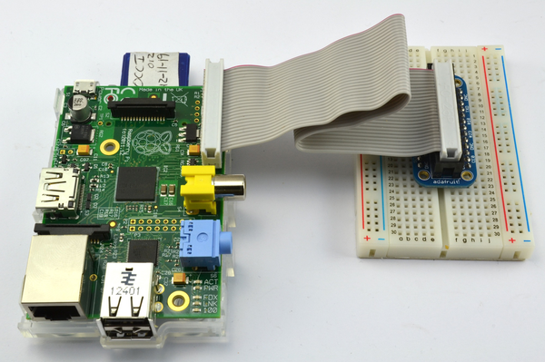
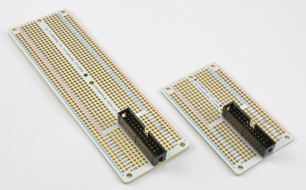
These boards are ready-made Printed Circuit Boards (PCB) that have the same layout of tracks and holes as a breadboard. This allows you to transfer your breadboard design to the Perma-Proto board without having to redesign it. The board comes complete with a socket to accept the cable and plug of the Cobbler.
Use a Raspberry Squid RGB LED (Figure 9-12).
The Raspberry Squid is an RGB LED with built-in series resistors and female header leads, so that it can be plugged directly onto the GPIO pins of a Raspberry Pi. The Squid has color-coded leads. The black lead goes to one of the GPIO GND pins and the red, green, and blue leads go to GPIO pins used for the red, green, and blue channels. The red, green, and blue outputs can be simple digital outputs or PWM outputs (Recipe 10.3) that allow you to mix different colors.
Instructions for making your own Squid can be found at https://github.com/simonmonk/squid, but you can also buy ready-made Squid from http://monkmakes.com.
The Squid has a Python library that is installed using the following commands:
$ git clone https://github.com/simonmonk/squid.git $ cd squid $ sudo python setup.py install
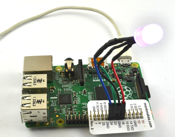
Inside the example folder, you will find the program test_led.py, which tells you pretty much all you need to know about using the Raspberry Squid.
fromsquidimport*importtimergb=Squid(18,23,24)rgb.set_color(RED)time.sleep(2)rgb.set_color(GREEN)time.sleep(2)rgb.set_color(BLUE)time.sleep(2)rgb.set_color(WHITE)time.sleep(2)rgb.set_color(WHITE,300)time.sleep(2)
Having imported the squid library, you can create a new Squid object, supplying the three pins to be used for its red, green, and blue channels (in this case, 18, 23, and 24). You can then set the color by using the set_color method, which takes either the name of a color constant (RED, GREEN, WHITE, etc.) or a tuple of three values each between 0 and 100 for the red, green, and blue channels. The optional second parameter to set_color is the overall brightness.
After the color is set, time.sleep(2) is used to create a two-second delay before the next color change.
You do not need to use all three color channels of a Squid, and it can be quite handy to just check that a GPIO pin is turning on and off as you expect before attaching some other electronics to it.
For information on the Squid library, see https://github.com/simonmonk/squid.
For information on the Squid Button, see Recipe 9.11.
Recipe 10.10 is an example project that controls an RGB LED (Squid or breadboard-based).
Use a Squid Button.
The Squid Button (Figure 9-13) is a push button with female header leads connected to the contacts so that you can plug it directly into the GPIO connector of a Raspberry Pi. The Squid Button also includes a low-value resistor that limits the current that would flow if the Squid Button were to be accidentally connected to a digital output rather than a digital input.

The Squid Button is a natural companion to the Squid RGB LED and shares the same Python library (see Recipe 9.10 to install this library).
The Squid Button could be used directly with the RPi.GPIO library, but the squid library provides key debouncing (see https://github.com/simonmonk/squid) to prevent accidental multiple presses of the button. The file test_button.py in the examples folder of the squid library illustrates the use of the button.
frombuttonimport*importtimeb=Button(7)whileTrue:ifb.is_pressed():(time.time())
The number (in this case, 7) indicates the GPIO pin that the button is connected to. The other pin is connected to GND.
The Squid button is useful for testing projects that use a digital input, but since the button is suitable for panel mounting, you can also build it into more permanent projects.
For information on the squid library, see https://github.com/simonmonk/squid.
For more information on using switches, see Recipes 12.1, 12.2, 12.3, 12.4, 12.5, and 12.6.
For information on the Squid RGB LED, see Recipe 9.10.
Use a pair of resistors as a potential divider to reduce the output voltage. Figure 9-14 shows how you might use the 5V serial connection of an Arduino to a Raspberry Pi.
To make this recipe, you will need:
270Ω resistor (see “Resistors and Capacitors” in Appendix A)
470Ω resistor (see “Resistors and Capacitors” in Appendix A)
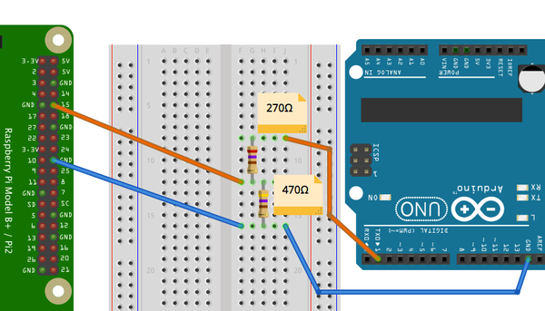
The TXD signal from the Pi is a 3.3V output. This can be connected directly to a 5V input on the Arduino without any problem. The Arduino module will recognize anything over about 2.5V as being high.
The problem arises when you need to connect the 5V output of the Arduino module to the RXD pin of the Pi. This must not be connected directly to the RXD input. The 5V signal could damage the Pi. Instead, the two resistors shown in Figure 9-14 are used.
The resistors used here will draw a current of 6mA. Given that the Pi uses a fairly hefty 500mA, this will not noticeably affect the current consumption of the Pi.
If you want to minimize the current used by the potential divider, then use larger value resistors, scaled proportionally—for example, 27kΩ and 47kΩ, which will draw a miserly 60 µA.
For more information on connecting Raspberry Pi to Arduino, see Chapter 16.
If you have multiple signals to convert between 3.3V and 5V, then it’s probably best to use a multichannel level converter module—see Recipe 9.13.
Use a bidirectional level converter module, such as the ones shown in Figure 9-15.
These modules are very easy to use. One side has the power supply at one voltage and a number of channels that can be either inputs or outputs at that voltage. The pins on the other side of the module have a power pin at the second voltage, and all the inputs and outputs on that side are automatically converted to the voltage level for that side.
These level converters are available with differing numbers of channels. The two shown in Figure 9-15 have four and eight channels.
Sources for such level converters can be found in Appendix A.
See Recipe 9.12, especially if you have only one or two levels to convert.
Normally 5V logic inputs will accept 3.3V outputs without a problem, however in some cases, such as when using LED strips (Recipe 14.7), this may not be the case, in which case a transistor or one of the modules described above can be used to raise the logic level.
A typical project using a Raspberry Pi requires 5V at up to about 600mA (see Recipe 1.3). The requirement for 5V is strict. You should not try to power your Pi from more or less than 5V. In practice, this means you are most likely to use a battery at a higher voltage than 5V—say, 9V—and use a voltage regulator to drop the voltage to 5V.
The relatively high power requirement of the Pi makes it unsuitable for powering from, say, a small 9V battery or even a set of AAA batteries. Most suitable would be a pack made up of six rechargeable AA batteries and a voltage regulator.
Figure 9-16 shows how you can use a voltage regulator with a battery pack to power a Pi through the 5V pin on the GPIO connector.
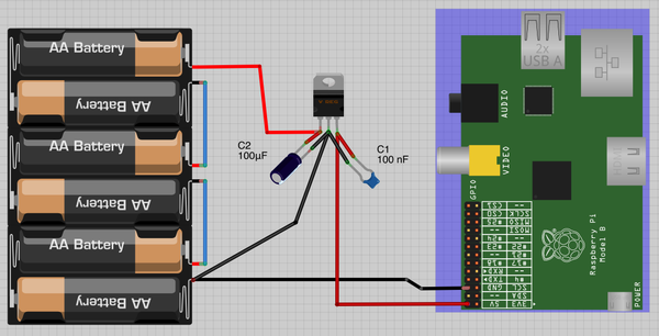
The 7805 voltage regulator will get pretty hot. If it gets too hot, its thermal cutout will kick in and the voltage at its output will drop, probably causing the Pi to reset. A heat sink that clips onto the integrated circuit (IC) will help with this.
An alternative solution, and a cooler one, is to use a RasPiRobot Board V3 (Recipe 9.18), as shown in Figure 9-17.
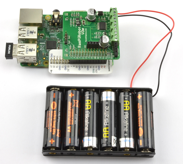
As well as being a motor driver, the RasPiRobot Board V3 has a built-in switched-mode power supply that will take an input of between 7V and 12V and supply the Raspberry Pi with 5V. Because the RasPiRobot Board V3 power supply is an efficient switching power supply rather than a linear regulator like the 7805, it will not get hot under normal use of the Raspberry Pi.
The 7805 requires the input voltage to be at least 2V above 5V. You can also buy low dropout (LDO) regulators, such as the LM2940. The LM2940 has the same pinout as the 7805 but only requires the input to be 0.5V above the 5V output. However, remember that nominally, 1.5V AA cells soon drop to about 1.2V. So a pack of four of them is unlikely to provide enough voltage for more than a few minutes. A pack of six will be fine.
The example above uses a 9V battery pack, but if you want to fit your Raspberry Pi into an automobile or RV’s 12V supply, this recipe will still work. You will also need to use a small monitor that can be powered from direct current (DC). Such devices are fairly easily found, as they are commonly used with closed-circuit camera systems.
Another way to power your Raspberry Pi from a battery is to use a ready-made cellphone charger that accepts AA batteries. Make sure that it can cope with 600mA or more.
Recipe 9.15 shows you how to power a Raspberry Pi from a LiPo battery pack.
For more information on using the RasPiRobot Board V3, see Recipe 9.18.
Use a boost regulator module (Figure 9-18). The module shown is from SparkFun, but similar designs are available on eBay more cheaply.
As always with such low-cost purchases from eBay, you should test the module thoroughly before using it. They do not always work exactly as advertised, and quality can be quite variable.
The advantage of this kind of module is that it acts as both a voltage regulator to supply 5V to the Pi and also has a USB socket of its own to supply power to its charging circuit. If you plug the Pi’s power adapter into the socket on the charger, the Pi will be powered and the battery charged, allowing you to unplug the USB power and use the Pi on the battery for as long as it has enough power.
With a 1300mA LiPo battery, you could expect the Pi to be powered for two or three hours.
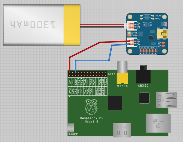
If you plan to handle the charging of the battery elsewhere, you can just go for a boost converter module, without the charger, at a lower cost.
The Raspberry Pi Sense HAT (Figure 9-19) is a useful and somewhat confusingly named interface board for the Raspberry Pi. Yes, it includes sensors—in fact, it can measure temperature, relative humidity, and atmospheric pressure (Recipe 13.10). It also has an accelerometer, gyroscope (Recipe 13.13), and magnetometer (Recipe 13.14) for navigation type projects. It also has a full-color 8×8 LED matrix display (Recipe 14.3).
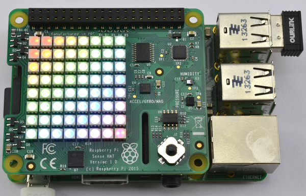
The Sense HAT requires a Raspberry Pi with a 40-pin GPIO header, so you will not be able to use it on an older Raspberry Pi with a 26-pin header.
The Sense HAT requires some software to be installed before you can use it. The process is not complicated, but it can take quite a while.
Note that by the time you read this, you might find that Raspbian already includes all the software that you need for the Sense HAT. If this is the case, running these commands will not cause any problems; the installer will just tell you that it has nothing to do.
Install the Sense HAT Python library by using the command:
$ sudo apt-get install sense-hat
This installer will actually enable I2C automatically, so you do not need to follow the usual I2C setup (Recipe 9.3).
The Sense HAT’s display uses a graphics library called Python Image Library (PIL), which must be installed by using the command:
$ sudo pip-3.2 install pillow
Installation will take a while, after which you should reboot if I2C was not already enabled.
There are more recipes that use the Sense HAT in this book, but for now, you can just check that everything is working by opening a Python console using:
$ sudo python
Then enter the following commands into the Python console:
>>> from sense_hat import SenseHat
>>> hat = SenseHat()
>>> hat.show_message('The Raspberry Pi Cookbook')
The LED matrix should then display the text of the message above, scrolling it across the screen.
The programming reference for the Sense HAT, at https://pythonhosted.org/sense-hat/api/.
To measure temperature, humidity, and atmospheric pressure, see Recipe 13.10.
To use the Sense HAT’s accelerometer and gyroscope, see Recipe 13.13.
To use the magnetometer to detect north and detect the presence of a magnet, see Recipes 13.14 and 13.16, respectively.
Plug the HAT into your Raspberry Pi and install the Explorer HAT Pro Python library.
Figure 9-20 shows a Pimoroni Explorer HAT Pro on a Raspberry Pi B+. Note that this HAT will only work on a 40-pin Raspberry Pi.
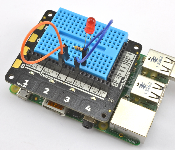
The Explorer HAT Pro has some useful input/output options as well as an area where a small solderless breadboard can be attached. Its features include:
To install the Python library for the Explorer HAT Pro, run the following command:
$ sudo pip install explorerhat
Once the library is installed, you can try a little experiment to make the built-in red LED blink.
importexplorerhat,timewhileTrue:explorerhat.light.red.on()time.sleep(0.5)explorerhat.light.red.off()time.sleep(0.5)
Open an editor (nano or IDLE) and paste in the following code. As with all the program examples in this book, you can download the program from the Code section of the Raspberry Pi Cookbook website, where it is called explorer_blink.py.
The Explorer HAT Pro provides four buffered inputs and outputs—that is inputs and outputs that are not connected directly to the Raspberry Pi, but to chips on the Explorer HAT Pro. This means that if you accidentally connect things incorrectly, the Explorer HAT Pro will be damaged rather than your Raspberry Pi.
You can use the Explorer HAT for capacitative touch sensing (Recipe 13.18).
Figure 9-21 shows the RaspiRobot board (version 3). The board has a dual-motor controller that can be used for two DC motors or a single stepper motor. It can supply 5V power to the Raspberry Pi by using its built-in switched-mode voltage regulator. The board has two switch inputs and two high-current (2A) outputs, and provides easy connections to a HC-SR04 rangefinder and the I2C interfaces of the Raspberry Pi.
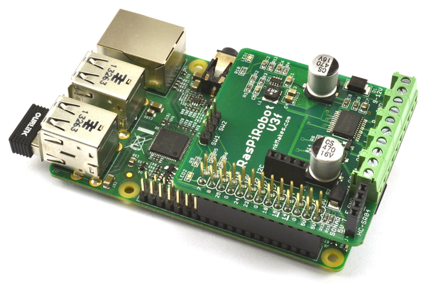
The RaspiRobot Board V3 has its own Python library that you need to download and install, using the following commands:
$ git clone https://github.com/simonmonk/raspirobotboard3.git $ cd raspirobotboard3/python $ sudo python setup.py install
Fit your RasPiRobot V3 onto your Raspberry Pi and then power up the Raspberry Pi. You can try out a few commands with the RaspiRobot board, using just the Python console without attaching external power or motors to the RaspiRobot board. Since the RaspiRobot board library uses the GPIO port, you will need to start Python as a superuser by using this command:
$ sudo python
When you first power up, you should find that both LEDs on the RaspiRobot board will be lit. Now enter the following commands, and both LEDs should turn off as the library is initialized:
>>>fromraspirobotboardimport*>>>rr=RRB3()
Try turning one of the LEDs on and off, using these commands:
>>>rr.set_led1(1)>>>rr.set_led1(0)
The RaspiRobot board has two pairs of pins, each designed to be connected to a switch. These are labeled SW1 and SW2 on the board. You can test whether SW1 is closed by using the command:
>>>(rr.sw1_closed())False
Shorting the two pins of SW1 together with a screwdriver and issuing the command again will return True.
Other commands are available to set the two open collector outputs (set_oc1 and set_oc2) and motor control commands (forward, reverse, left, right, and stop). See http://www.raspirobot.com for the full command reference.
To learn how to use this board to make a roving robot, see Recipe 11.10.
To use the RaspiRobot board to control a bipolar stepper motor, see Recipe 11.9.
The Pi Plate (Figure 9-22) is a prototyping board rather than an interface board like the RaspiRobot board (Recipe 9.18). In other words, it does not include any electronics—it is designed for you to solder your own components to a prototyping area.
The board has an area where a 16-pin, surface-mount chip can be used, and a row of four holes, spaced more widely, where a screw terminal can be soldered in place.
The board has screw terminals on two sides, which are connected to all the GPIO pins. You can ignore the prototyping area entirely and just use the screw terminals to attach wires to the GPIO pins.

The board design has a grid of holes at a pitch of the standard 0.1 inch used by most through-hole components, including DIL ICs. You solder components to the board by pushing the leads through the holes at the top and soldering the connections underneath.
The tracks that connect the holes are clearly visible on the top of the board, and the board is divided into several zones. There is an area with central power busses intended for DIL ICs, as well as a general prototyping area and areas for a surface-mount chip and extra screw terminals.
Having soldered the components into place, you will need extra wires to link everything together. These can be run on the bottom or top of the board, or both if the design is complicated.
It’s a good idea to plan out the layout before you start soldering.
In the following instructions, you will build an RGB LED onto a Pi Plate, using the layout shown in Figure 9-23. This recipe is a version of Recipe 10.10, which is the same except that the design is built onto a solderless breadboard.
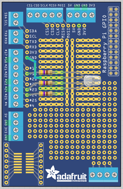
The first step is to solder the resistors into place. Bend the leads and push them through the appropriate holes in the board. Then flip the board over and touch the soldering iron to where the leads emerge from the holes for a second or so before applying the solder, which should flow around the lead (Figure 9-24).
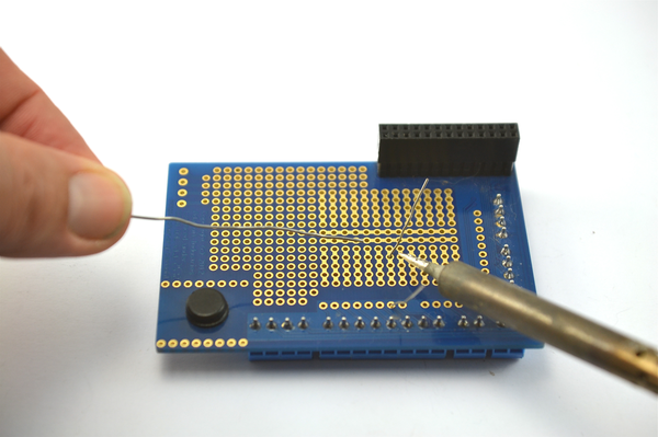
When you have soldered both ends, snip off the excess lead and repeat for the other two resistors (Figure 9-25).
Now solder the LED into place, taking care to get it facing the right way. The longest lead is the common cathode and should be the only LED lead attached to the strip of holes that is not connected to any resistor. Very occasionally, you will find LEDs where the longer lead is not the positive lead. This is often the case with infrared LEDs. If you aren’t sure, check the datasheet for the LED or the supplier’s information page.
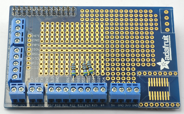
You will also need to solder a short length of wire from that row to the GND connection on the Pi Plate (Figure 9-26).
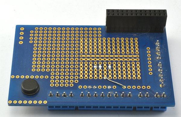
When the board is complete, it should look like Figure 9-27.
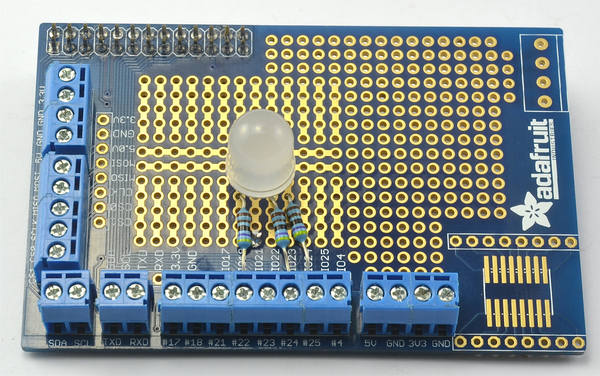
You can try out the LED using the Python program from Recipe 10.10.
There is more information about this product at the Adafruit website.
Use a Perma-Proto Pi HAT (Figure 9-28).
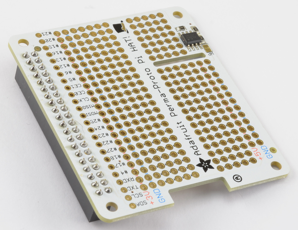
With the advent of the Raspberry Pi B+ with a 40-pin GPIO header, a new standard for add-on boards for the Raspberry Pi was defined, called HAT (Hardware At Top). You do not have to stick to this standard, especially if you are just making a one-off product for yourself, but if you are designing a product to sell, then it may make sense for you to conform to the HAT standard.
The HAT standard defines the size and shape of the PCB and also mandates that the PCB has an Electrically Erasable Read-Only Memory (EEPROM) chip soldered onto the board. This chip is connected to the ID_SD and ID_SC pins of the GPIO header, and in the future will allow some configuration of the Pi and even automatic loading of software to occur when the Raspberry Pi is booted up with a HAT attached.
The prototyping area of the board is made up of some power rails and a breadboard format layout of two rows of five holes plus power rails down both sides of the board.
If you don’t care about programming the EEPROM, then you can stop here. However, if you want to add your own custom information onto the HAT’s EEPROM, then read on to the Discussion next.
The HAT standard makes a lot of sense. However, at the time of writing, Raspbian does not make use of any information written in the HAT’s EEPROM. This is likely to change in the future and leads to the exciting possibility of HATs automatically doing things like enabling I2C and installing Python libraries for their hardware, just by being present on the Raspberry Pi.
To write data into the EEPROM, you first need to enable the hidden I2C port used by the ID_SD and ID_SC pins that are used to read and write to the EEPROM. To do that, you will need to edit /boot/config.txt by adding in or uncommenting the line:
dtparam=i2c_vc=on
Once this is done, reboot your Raspberry Pi, and you should then be able to detect that the I2C EEPROM is attached to the I2C bus using i2c tools (Recipe 9.4).
$ i2cdetect -y 0 0 1 2 3 4 5 6 7 8 9 a b c d e f 00: -- -- -- -- -- -- -- -- -- -- -- -- -- 10: -- -- -- -- -- -- -- -- -- -- -- -- -- -- -- -- 20: -- -- -- -- -- -- -- -- -- -- -- -- -- -- -- -- 30: -- -- -- -- -- -- -- -- -- -- -- -- -- -- -- -- 40: -- -- -- -- -- -- -- -- -- -- -- -- -- -- -- -- 50: 50 -- -- -- -- -- -- -- -- -- -- -- -- -- -- -- 60: -- -- -- -- -- -- -- -- -- -- -- -- -- -- -- -- 70: -- -- -- -- -- -- -- --
You can see from the result of the i2cdetect command that the EEPROM has an I2C address of 50. Note that the option -y 0 rather than the usual -y 1 is used because this is not the normal I2C bus on pins 2 and 3, but rather the I2C bus dedicated to the HAT EEPROM.
To read and write the EEPROM, you need to download some tools by using the commands below:
$ git clone https://github.com/raspberrypi/hats.git $ cd hats/eepromutils $ make
Writing the EEPROM is a three-step process. First, you must edit the file eeprom_settings.txt. Change at least the product_id, product_version, vendor, and product fields to be your company name and product name. Note that there are lots of other options in this file, which is well-documented. They include specifying back-powering options, GPIO pins used, etc.
Second, after editing the file, run the command below to convert the text file into a file suitable for writing to the EEPROM (rom_file.eep).
$ ./eepmake eeprom_settings.txt rom_file.eep Opening file eeprom_settings.txt for read UUID=7aa8b587-9c11-4177-bf14-00e601c5025e Done reading Writing out... Done.
Finally, copy rom_file.eep onto the EEPROM by running the command below:
sudo ./eepflash.sh -w -f=rom_file.eep -t=24c32 This will disable the camera so you will need to REBOOT after this... This will attempt to write to i2c address 0x50. Make sure there is... This script comes with ABSOLUTELY no warranty. Continue only if you... Do you wish to continue? (yes/no): yes Writing... 0+1 records in 0+1 records out 127 bytes (127 B) copied, 2.52071 s, 0.1 kB/s Done. pi@raspberrypi ~/hats/eepromutils $
Once writing is complete, you can read the ROM back using the commands below:
$ sudo ./eepflash.sh -r -f=read_back.eep -t=24c32 $ ./eepdump read_back.eep read_back.txt $ more read_back.txt
You can find the Raspberry Pi HAT design guide here: https://github.com/raspberrypi/hats.
There are many ready-made HATs on the market, including the Stepper Motor (Recipe 11.8), Capacitative Touch (Recipe 13.18), and 16-Channel PWM (Recipe 11.1) HATs from Adafruit, as well as the Pimoroni Explorer HAT Pro (Recipe 9.16).
Use a Raspberry Pi Compute module.
The Raspberry Pi Compute module (shown on the left of Figure 9-29 next to its IO board on the right) is a board containing the Raspberry Pi System on a Chip (SoC) with 512 MB RAM in the form factor of a SODIMM memory module such as you would fit into a laptop when upgrading its memory.
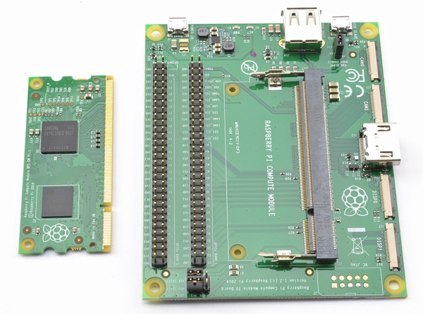
The hardware is based on the original Raspberry Pi, but instead of an SD card slot, there is a 4GB Flash chip built onto the board.
The idea behind this board is that product developers can create their own PCB with a SODIMM socket on it into which the Pi Compute module could be plugged. The companion IO board is just there for you to prototype your designs using the compute board.
This board was released before the Raspberry Pi Zero (Recipe 9.22), and at the time of writing seems somewhat redundant as it is more expensive than the Zero, does not perform as well, and is only slightly smaller. It also lacks any of the connectors present on the Pi Zero, which may be just what you need in your product without having to design your own PCB.
A smattering of products have been produced that use the Compute module, but without a hardware refresh and/or big price drop, this board may have an uncertain future.
For full information on the Pi Compute module, see https://www.raspberrypi.org/blog/raspberry-pi-compute-module-new-product/.
The small size and extremely low cost of the Pi Zero make it the ideal choice for embedding in electronics projects.
Figure 9-30 shows a Raspberry Pi Zero.
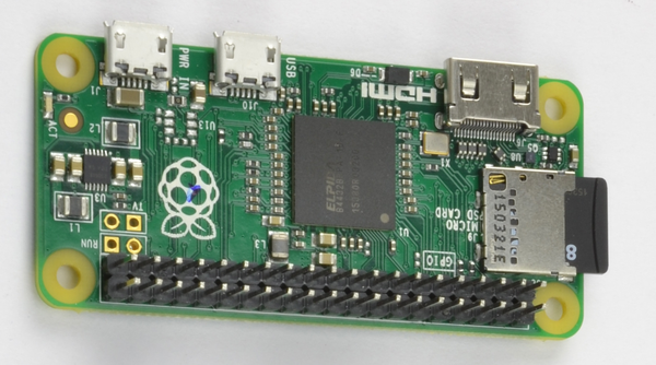
The Pi Zero is supplied without header pins attached, so your first job is likely to be to solder pins to it. Suitable header pins are available in Pi Zero starter kits, such as the one supplied by Pi Hut.
You can also use the easier-to-find single-row header pins, just by soldering two lengths side by side.
With only one USB connector—and a micro USB OTG (on the go) connector at that, you will need a USB adapter and USB hub to be able to plug in a USB WiFi dongle, keyboard, and mouse in order to set up the Pi Zero.
Alternatively, you can use a console cable as described in Recipe 2.6 to set up WiFi by editing /etc/network/interfaces as described in Recipe 2.5. Once that is set up, you can connect to the Pi Zero wirelessly using SSH (Recipe 2.7).
For a comparison of the Raspberry Pi models available, see Recipe 1.1.
In this chapter, you come to grips with the control of electronics through the Raspberry Pi’s GPIO connector.
Most of the recipes require the use of solderless breadboard and male-to-female and male-to-male jumper wires (see Recipe 9.8). To maintain compatibility with older 26-pin Raspberry Pi models, all the breadboard examples here only use the top 26 pins common to both GPIO layouts (see Recipe 9.1).
Be sure to check out the accompanying video for this recipe at http://razzpisampler.oreilly.com.
Connect an LED to one of the GPIO pins using a 470Ω or 1kΩ series resistor to limit the current. To make this recipe, you will need:
Breadboard and jumper wires (see “Prototyping Equipment”)
470Ω resistor (see “Resistors and Capacitors”)
LED (see “Opto-Electronics”)
Figure 10-1 shows how you can wire this LED using a solderless breadboard and male-to-female jumper leads.
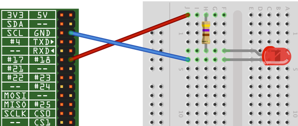
Having connected the LED, we need to be able to turn it on and off using commands from Python.
Start a Python console from the Terminal with superuser access and enter these commands:
$ sudo python >>> import RPi.GPIO as GPIO >>> GPIO.setmode(GPIO.BCM) >>> GPIO.setup(18, GPIO.OUT) >>> GPIO.output(18, True) >>> GPIO.output(18, False)
This will turn your LED on and off.
LEDs are a very useful, cheap, and efficient way of producing light, but you do have to be careful how you use them. If they are connected directly to a voltage source (such as a GPIO output) that is greater than about 1.7 volts, they will draw a very large current. This can often be enough to destroy the LED or whatever is providing the current—which is not good if your Raspberry Pi is providing the current.
You should always use a series resistor with an LED because the series resistor is placed between the LED and the voltage source, which limits the amount of current flowing through the LED to a level that is safe for both the LED and the GPIO pin driving it.
Raspberry Pi GPIO pins are only guaranteed to provide about 3mA or 16mA of current (depending on the board and number of pins in use)—see Recipe 9.2. LEDs will generally illuminate with any current greater than 1mA, but will be brighter with more current. Use Table 10-1 as a guide to selecting a series resistor based on the type of LED; the table also indicates the approximate current that will be drawn from the GPIO pin.
| LED type | Resistor | Current (mA) |
|---|---|---|
|
Red |
470Ω |
3.5 |
|
Red |
1kΩ |
1.5 |
|
Orange, yellow, green |
470Ω |
2 |
|
Orange, yellow, green |
1kΩ |
1 |
|
Blue, white |
100Ω |
3 |
|
Blue, white |
270Ω |
1 |
As you can see, in all cases, it is safe to use a 470Ω resistor. If you are using a blue or white LED, you can reduce the value of the series resistor considerably without risk of damaging your Raspberry Pi.
If you want to extend the experiments that you made in the Python console into a program that makes the LED blink on and off repeatedly, you could paste the following code into the IDLE (Recipe 5.2) or nano (Recipe 3.6) editors. Save the file as led_blink.py. You can also download the program from the Downloads section on the Raspberry Pi Cookbook website.
importRPi.GPIOasGPIOimporttimeGPIO.setmode(GPIO.BCM)GPIO.setup(18,GPIO.OUT)while(True):GPIO.output(18,True)time.sleep(0.5)GPIO.output(18,False)time.sleep(0.5)
Remember that to run the program, you must have superuser privileges for the RPi.GPIO library, so you need to use this command:
$ sudo python led_blink.py
Check out this handy series resistor calculator.
For more information on using breadboard and jumper wires with the Raspberry Pi, see Recipe 9.8.
Use a try: finally: construction and the GPIO.cleanup method.
The blink example from Recipe 10.1 can be rewritten to exit safely as shown below. The file for the code is called led_blink_safe.py.
importRPi.GPIOasGPIOimporttimeGPIO.setmode(GPIO.BCM)GPIO.setup(18,GPIO.OUT)try:while(True):GPIO.output(18,True)time.sleep(0.5)GPIO.output(18,False)time.sleep(0.5)finally:("Cleaning Up!")GPIO.cleanup()
Now, when you Ctrl-C the program to close it, GPIO.cleanup will be called before the program exits.
If cleanup is not called or the Pi is not rebooted, then pins set to be outputs will remain as outputs after the program has finished. If you were to start wiring up a new project, unaware of this problem, your new circuit might accidentally short a GPIO output to one of the supply rails or another GPIO pin in the opposite state.
A typical scenario where this might happen would be if you were to connect a push switch, connecting a GPIO pin that you had configured as an output and HIGH to GND, such as in Recipe 12.1.
In summary, either be careful when swapping hardware or use GPIO.cleanup as shown earlier, or reboot your Pi. In any case, its a good idea to power down your Pi while you are connecting new hardware to it.
For more information on exception handling in Python, see Recipe 7.10.
The RPi.GPIO library has a pulse-width modulation (PWM) feature that allows you to control the power to an LED and its brightness.
To try it out, connect an LED as described in Recipe 10.2 and run this test program (led_brightness.py):
importRPi.GPIOasGPIOled_pin=18GPIO.setmode(GPIO.BCM)GPIO.setup(led_pin,GPIO.OUT)pwm_led=GPIO.PWM(led_pin,500)pwm_led.start(100)whileTrue:duty_s=raw_input("Enter Brightness (0 to 100):")duty=int(duty_s)pwm_led.ChangeDutyCycle(duty)
If you are using Python 3 rather than Python 2, change the command raw_input to input.
Run the Python program, and you will be able to change the brightness by entering a number between 0 and 100:
pi@raspberrypi ~ $ sudo python led_brightness.py Enter Brightness (0 to 100):0 Enter Brightness (0 to 100):20 Enter Brightness (0 to 100):10 Enter Brightness (0 to 100):5 Enter Brightness (0 to 100):1 Enter Brightness (0 to 100):90
Exit the program by pressing Ctrl-C.
PWM is a clever technique where you vary the length of pulses while keeping the overall number of pulses per second (the frequency in Hz) constant. Figure 10-2 illustrates the basic principle of PWM.

At high frequencies, the measured PWM frequency varies somewhat from the frequency supplied as an argument. This might change in later versions of the PWM feature of RPi.GPIO.
You can change the PWM frequency by modifying this line:
pwm_led=GPIO.PWM(led_pin,500)
The value is in Hz, so in this case, the frequency is set to 500 Hz.
Table 10-2 compares frequencies specified in the second parameter to GPIO.PWM to the actual frequency on the pin measured with an oscilloscope.
| Requested frequency | Measured frequency |
|---|---|
|
50 Hz |
50 Hz |
|
100 Hz |
98.7 Hz |
|
200 Hz |
195 Hz |
|
500 Hz |
470 Hz |
|
1 kHz |
890 Hz |
|
10 kHz |
4.4 kHz |
I also found that as the frequency increased, its stability decreased. This means that this PWM feature is no good for audio but plenty fast enough for controlling the brightness of LEDs or the speed of motors.
For more information on PWM, see Wikipedia.
Recipe 10.10 uses PWM to change the color of an RGB LED, and Recipe 11.4 uses PWM to control the speed of a DC motor.
For more information on using breadboard and jumper wires with the Raspberry Pi, see Recipe 9.8. You can also control the brightness of the LED with a slider control—see Recipe 10.9.
For another approach to controlling the color of an RGB LED using the Squid RGB LED library, see Recipe 9.10.
Use a piezo-electric buzzer connected to a GPIO pin.
Most small piezo buzzers work just fine using the arrangement shown in Figure 10-3. The one I used is an Adafruit-supplied component (see “Miscellaneous”). You can connect the buzzer pins directly to the Raspberry Pi using female-to-female headers (see “Prototyping Equipment”).
These buzzers use very little current. However, if you have a large buzzer or just want to play it safe, then put a 470Ω resistor between the GPIO pin and the buzzer lead.
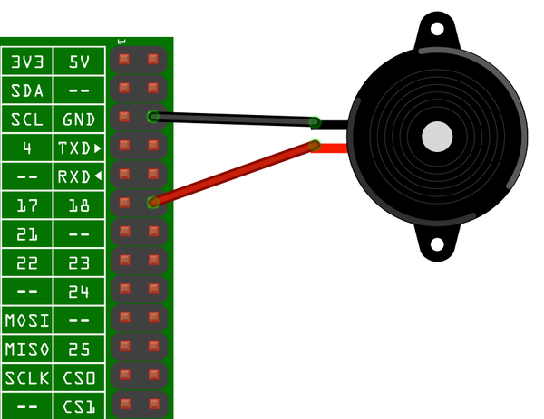
Paste the following code into the IDLE (Recipe 5.2) or nano (Recipe 3.6) editors. Save the file as buzzer.py. You can also download the program from the Downloads section of the Raspberry Pi Cookbook website.
importRPi.GPIOasGPIOimporttimebuzzer_pin=18GPIO.setmode(GPIO.BCM)GPIO.setup(buzzer_pin,GPIO.OUT)defbuzz(pitch,duration):period=1.0/pitchdelay=period/2cycles=int(duration*pitch)foriinrange(cycles):GPIO.output(buzzer_pin,True)time.sleep(delay)GPIO.output(buzzer_pin,False)time.sleep(delay)whileTrue:pitch_s=raw_input("Enter Pitch (200 to 2000): ")pitch=float(pitch_s)duration_s=raw_input("Enter Duration (seconds): ")duration=float(duration_s)buzz(pitch,duration)
When you run the program, it will first prompt you for the pitch in Hz and then the duration of the buzz in seconds:
$ sudo python buzzer.py Enter Pitch (2000 to 10000): 2000 Enter Duration (seconds): 20
Piezo buzzers don’t have a wide range of frequencies, nor is the sound quality remotely good. However, you can vary the pitch a little. The frequency generated by the code is very approximate.
The program works by simply toggling the GPIO pin 18 on and off with a short delay in between. The delay is calculated from the pitch. The higher the pitch (frequency), the shorter the delay needs to be.
You can find the datasheet for the piezo buzzer here: http://bit.ly/Iwkv2R.
These high-power LEDs use far too much current to light directly from a GPIO pin. They also require 12V rather than the 3.3V. To control such a high-power load, you need to use a transistor.
In this case, you will use a high-power type of transistor called a metal–oxide–semiconductor field-effect transistor (MOSFET), which costs less than a dollar but can handle loads up to 30 amps—many times more than is required for the high-power LEDs. The MOSFET used is a FQP30N06L (see “Transistors and Diodes”).
Figure 10-4 shows how you can connect a MOSFET on a breadboard. Make sure that you correctly identify the positive and negative supply leads for the LED module.
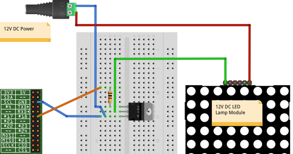
To make this recipe, you will need:
Breadboard and jumper wires (see “Prototyping Equipment”)
1kΩ resistor (see “Resistors and Capacitors”)
FQP30N06L N-Channel MOSFET or TIP120 Darlington transistor (see “Transistors and Diodes”)
12V power adapter
12V DC LED module
The Python code to turn the LED panel on and off is exactly the same as if we were controlling a single low-power LED without the MOSFET (see Recipe 10.1).
You can also use PWM with the MOSFET to control the brightness of the LED module (see Recipe 10.3).
Whenever you need to power anything significant using the GPIO connector, use batteries or an external power adapter. The GPIO connector can only supply relatively low currents (Recipe 9.2). In this case, you’ll use a 12V DC power adapter to provide the power to the LED panel. Pick a power adapter that has sufficient power handling. Therefore, if the LED module is 5W, then you need at least a 12V 5W power supply (6W would be better). If the power supply specifies a maximum current rather than power, then you can calculate its power by multiplying the voltage by the maximum current. Therefore, a 500mA 12V power supply can provide 6W of power.
The resistor is necessary to ensure that the peak currents that occur as the MOSFET switches from off to on and vice versa do not overload the GPIO pin. The MOSFET switches the negative side of the LED panel, so the positive supply is connected directly to the positive side of the LED panel, and the negative side of the LED panel is connected to the drain of the MOSFET. The source connection of the MOSFET is connected to GND, and the MOSFET’s gate pin controls the flow of current from the drain to the source. If gate voltage is above 2V or so, the MOSFET will turn on and current flows through both it and the LED module.
The MOSFET used here is a FQP30N06L. The L at then end means that it is a logic-level MOSFET whose gate threshold voltage is suitable for use with 3.3V digital outputs. The non-L version of this MOSFET is also likely to work just fine, but you cannot guarantee it as the specified range of gate threshold voltages is 2V to 4V. Therefore, if you were unlucky and got a MOSFET at the 4V end, it would not switch well.
An alternative to using a MOSFET is to use a power Darlington transistor like the TIP120. This has a compatible pinout with the FQP30N06L, so you can keep the same breadboard layout.
This circuit is suitable for controlling the power to other low-voltage DC devices. The only real exceptions are motors and relays, which require some extra treatment (see Recipe 10.6).
Check out the datasheet for the MOSFET.
If you would like to create a graphical user interface with which to control your LED module, see Recipe 10.8 for simple on/off control, and Recipe 10.9 for variable control of the brightness with a slider.
Use a relay and small transistor.
Figure 10-5 shows how you can connect a transistor and relay on a breadboard. Make sure that both the transistor and diode are placed the right way. The diode has a stripe at one end, and the transistor used here has one side flat and one curved.
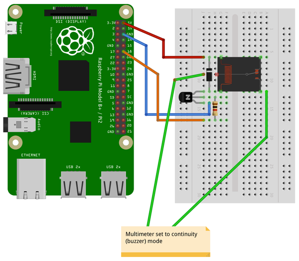
To make this recipe, you will need:
Breadboard and jumper wires (see “Prototyping Equipment”)
1kΩ resistor (see “Resistors and Capacitors”)
Transistor 2N3904 (see “Transistors and Diodes”)
1N4001 diode (see “Transistors and Diodes”)
5V relay (see “Miscellaneous”)
Multimeter
You can use the same LED blink program that you used in Recipe 10.1. If all is well, you’ll hear a click from the relay each time the contacts are closed. However, relays are slow mechanical devices, so don’t try to use them with PWM. It may damage the relay.
Relays have been around since the early days of electronics and have the great advantage of being easy to use, plus they’ll work in any situation where a switch would normally work—for example, when you’re switching AC (alternating current) or in situations where the exact wiring of the device being switched is unknown.
If the relay contacts are asked to exceed their specifications, then the relay’s life will be shortened. There will be arcing, and the contacts may eventually fuse together. There is also the possibility of the relay becoming dangerously hot. When in doubt, overspecify the relay contacts.
Figure 10-6 shows the schematic symbol, pin layout, and package of a typical relay.
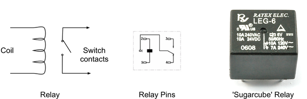
A relay is essentially a switch whose contacts are closed when an electromagnet pulls them together. Since the electromagnet and switch are not connected electrically in any way, this protects the circuit driving the relay coil from any high voltages on the switch side.
The downside of relays is that they are slow to operate and will eventually wear out after many hundreds of thousands of operations. This means they are only suitable for slow on/off control, and not for fast switching like PWM.
The coil of a relay requires about 50mA to close the connections. Because a Raspberry Pi GPIO pin is only capable of supplying about 3mA, you need to use a small transistor as a switch. You don’t need to use a high-power MOSFET like you did in Recipe 10.5, but instead you can just use a small transistor. This has three connections. The base (middle lead) is connected to the GPIO pin via a 1kΩ resistor to limit the current. The emitter is connected to GND, and the collector is connected to one side of the relay. The other side of the relay is connected to 5V on the GPIO connector. The diode is used to suppress any high-voltage pulses that occur when the transistor rapidly switches the power to the relay’s coil.
Although relays can be used to switch 110V or 240V AC, this voltage is very dangerous and should not be used on a breadboard. If you want to switch high voltages, use Recipe 10.7 instead.
For switching DC using a power MOSFET, see Recipe 10.5.
Use a PowerSwitch Tail II (see Figure 10-7). This handy device makes it really easy to switch AC equipment on and off from a Raspberry Pi. It has an AC socket on one end and a plug on the other, like an extension cable; the only difference is that the control box in the middle of the lead has three screw terminals. By attaching terminal 2 to GND and terminal 1 to a GPIO pin, the device acts like a switch to turn the appliance on and off.
You can use the same Python code that you did in Recipe 10.1 to use the PowerSwitch Tail, as shown in Figure 10-7.
The PowerSwitch Tail uses a relay, but to switch the relay, it uses a component called an opto-isolator, which has an LED shining onto a photo-TRIAC (a high-voltage, light-sensitive switch); when the LED is illuminated, the photo-TRIAC conducts, supplying current to the relay coil.
The LED inside the opto-isolator has its current limited by a resistor so that only 3mA flows through it when you supply it with 3.3V from a GPIO pin.
You will also find similar but cheaper devices to the PowerSwitch Tail for sale on eBay and Amazon.
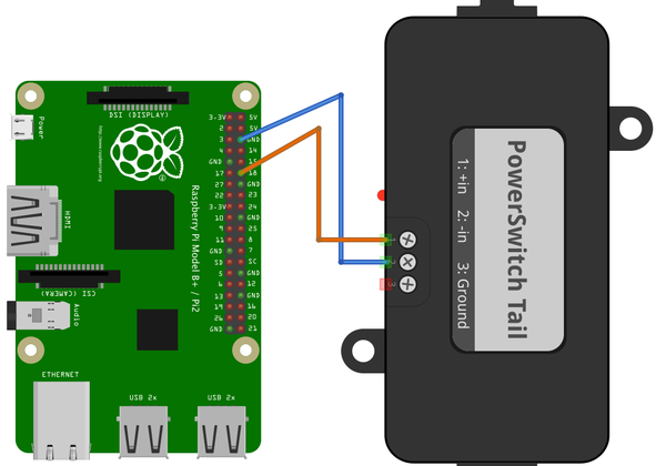
For switching DC using a power MOSFET, see Recipe 10.5; and for switching using a relay on a breadboard, see Recipe 10.6.
A 240V version of the PowerSwitch Tail is available as a kit.
Using the Tkinter user interface framework, write a Python program that uses a checkbox to turn the GPIO pin on and off (Figure 10-8).
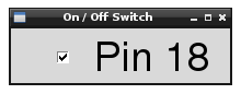
You’ll need to connect an LED or some other kind of output device to GPIO pin 18. Using an LED (Recipe 10.1) is the easiest option to start with.
Open an editor (nano or IDLE) and paste in the following code. As with all the program examples in this book, you can also download the program from the Code section of http://www.raspberrypicookbook.com, where it is called gui_switch.py.
fromTkinterimport*importRPi.GPIOasGPIOimporttimeGPIO.setmode(GPIO.BCM)GPIO.setup(18,GPIO.OUT)classApp:def__init__(self,master):frame=Frame(master)frame.pack()self.check_var=BooleanVar()check=Checkbutton(frame,text='Pin 18',command=self.update,variable=self.check_var,onvalue=True,offvalue=False)check.grid(row=1)defupdate(self):GPIO.output(18,self.check_var.get())root=Tk()root.wm_title('On / Off Switch')app=App(root)root.geometry("200x50+0+0")root.mainloop()
Note that you will need to run it with sudo because the RPi.GPIO requires you to have superuser privileges to access the GPIO hardware:
$ sudo python gui_switch.py
In Python 3, the Tkinter library has been renamed tkinter with a lowercase t.
The example program defines a class called App that contains most of the application code. Its initializer function creates a member variable called check_var that contains an instance of BooleanVar that is then supplied as the variable option to the checkbox. This ensures that every time the checkbox is clicked, the value in this variable will be changed. The command option runs the update command every time such a change occurs.
The update function simply writes the value in check_var to the GPIO output.
You can use this program to control an LED (Figure 10-8), a high-power DC device (Recipe 10.5), a relay (Recipe 10.6), or a high-voltage AC device (Recipe 10.7).
Using the Tkinter user interface framework, write a Python program that uses a slider to change the PWM duty cycle between 0 and 100 percent (Figure 10-9).
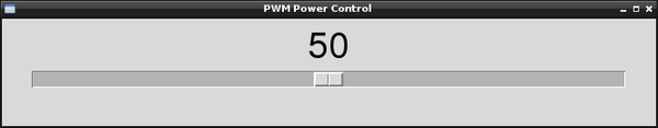
You will need to connect an LED or some other kind of output device to GPIO pin 18 that is capable of responding to a PWM signal. Using an LED (Recipe 10.1) is the easiest option to start with.
Open an editor (nano or IDLE) and paste in the following code. As with all the program examples in this book, you can also download the program from the Code section of http://www.raspberrypicookbook.com, where it is called gui_slider.py.
fromTkinterimport*importRPi.GPIOasGPIOimporttimeGPIO.setmode(GPIO.BCM)GPIO.setup(18,GPIO.OUT)pwm=GPIO.PWM(18,500)pwm.start(100)classApp:def__init__(self,master):frame=Frame(master)frame.pack()scale=Scale(frame,from_=0,to=100,orient=HORIZONTAL,command=self.update)scale.grid(row=0)defupdate(self,duty):pwm.ChangeDutyCycle(float(duty))root=Tk()root.wm_title('PWM Power Control')app=App(root)root.geometry("200x50+0+0")root.mainloop()
Note that you will need to run it with sudo because the RPi.GPIO requires you to have superuser privileges to access the GPIO hardware.
$ sudo python gui_slider.py
The example program defines a class called App that contains most of the application code. The command option runs the update command every time the value of the slider is changed. This updates the duty cycle of the output pin.
You can use this program to control an LED (Recipe 10.1), a DC motor (Recipe 11.4), or a high-power DC device (Recipe 10.5).
Use PWM to control the power to each of the red, green, and blue channels of an RGB LED.
To make this recipe, you will need:
Breadboard and jumper wires (see “Prototyping Equipment”)
Three 470Ω resistors (see “Resistors and Capacitors”)
RGB common cathode LED (“Opto-Electronics”)
A Perma-Proto (Recipe 9.9) or Pi Plate (see Recipe 9.19) to make a more permanent project (optional)
Figure 10-10 shows how you can connect your RGB LED on a breadboard. Make sure that the LED is the correct way around; the longest lead should be the second lead from the top of the breadboard. This connection is called the common cathode, as the negative connections (cathodes) of the red, green, and blue LEDs within the LED case have all their negative sides connected together to reduce the number of pins needed in the package.
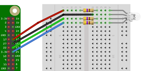
An alternative to using a breadboard is to use a Raspberry Squid (see Recipe 9.10).
The upcoming program has three sliders to control the red, green, and blue channels of the LED (Figure 10-11).
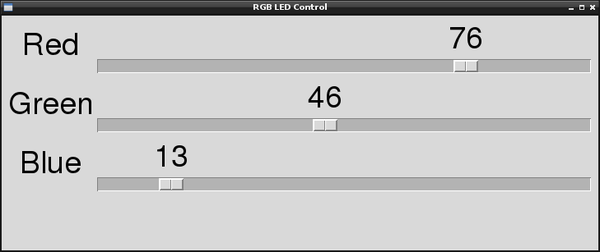
Open an editor (nano or IDLE) and paste in the following code. As with all the program examples in this book, you can also download the program from the Code section of http://www.raspberrypicookbook.com, where it is called gui_sliderRGB.py.
fromTkinterimport*importRPi.GPIOasGPIOimporttimeGPIO.setmode(GPIO.BCM)GPIO.setup(18,GPIO.OUT)GPIO.setup(23,GPIO.OUT)GPIO.setup(24,GPIO.OUT)pwmRed=GPIO.PWM(18,500)pwmRed.start(100)pwmGreen=GPIO.PWM(23,500)pwmGreen.start(100)pwmBlue=GPIO.PWM(24,500)pwmBlue.start(100)classApp:def__init__(self,master):frame=Frame(master)frame.pack()Label(frame,text='Red').grid(row=0,column=0)Label(frame,text='Green').grid(row=1,column=0)Label(frame,text='Blue').grid(row=2,column=0)scaleRed=Scale(frame,from_=0,to=100,orient=HORIZONTAL,command=self.updateRed)scaleRed.grid(row=0,column=1)scaleGreen=Scale(frame,from_=0,to=100,orient=HORIZONTAL,command=self.updateGreen)scaleGreen.grid(row=1,column=1)scaleBlue=Scale(frame,from_=0,to=100,orient=HORIZONTAL,command=self.updateBlue)scaleBlue.grid(row=2,column=1)defupdateRed(self,duty):pwmRed.ChangeDutyCycle(float(duty))defupdateGreen(self,duty):pwmGreen.ChangeDutyCycle(float(duty))defupdateBlue(self,duty):pwmBlue.ChangeDutyCycle(float(duty))root=Tk()root.wm_title('RGB LED Control')app=App(root)root.geometry("200x150+0+0")root.mainloop()
The code is similar in operation to the control for a single PWM channel, described in Recipe 10.9. However, in this case, you need three PWM channels and three sliders, one for each color.
The type of RGB LED used here is a common cathode. If you have the common anode type, then you can still use it, but connect the common anode to the 3.3V pin on the GPIO connector. You will then find that the slider becomes reversed, so a setting of 100 becomes off and 0 becomes full on.
When you are selecting an LED for this project, LEDs labeled diffused are best because they allow the colors to be mixed better.
If you just want to control one PWM channel, see Recipe 10.9.
For another approach to controlling the color of an RGB LED using the Squid RGB LED library, see Recipe 9.10.
Be sure to check out the accompanying video for this recipe at http://razzpisampler.oreilly.com.
The way to do this is to use a technique called Charlieplexing. The name comes from the inventor, Charlie Allen of the company Maxim, and the technique takes advantage of the feature of GPIO pins that allows them to be changed from outputs to inputs while a program is running. When a pin is changed to be an input, not enough current will flow through it to light an LED or influence other pins connected to the LED that are set as outputs.
Figure 10-12 shows the schematic for controlling six LEDs with three pins.
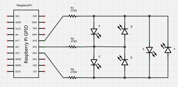
Figure 10-13 shows the breadboard layout for the LEDs and resistors.
To make this recipe, you will need:
Breadboard and jumper wires (see “Prototyping Equipment”)
Three 470Ω resistors (see “Resistors and Capacitors”)
Six LEDs (see “Opto-Electronics”)
Open an editor (nano or IDLE) and paste in the following code. As with all the program examples in this book, you can also download the program from the Code section of the Raspberry Pi Cookbook website, where it is called charlieplexing.py.
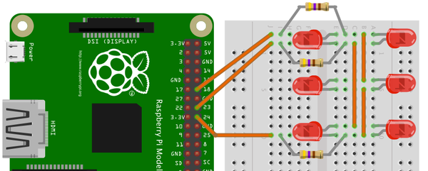
This example code prompts you to enter a number between 0 and 5, which then lights one of the six LEDs:
importRPi.GPIOasGPIOpins=[18,23,24]pin_led_states=[[1,0,-1],# A[0,1,-1],# B[-1,1,0],# C[-1,0,1],# D[1,-1,0],# E[0,-1,1]# F]GPIO.setmode(GPIO.BCM)defset_pin(pin_index,pin_state):ifpin_state==-1:GPIO.setup(pins[pin_index],GPIO.IN)else:GPIO.setup(pins[pin_index],GPIO.OUT)GPIO.output(pins[pin_index],pin_state)deflight_led(led_number):forpin_index,pin_stateinenumerate(pin_led_states[led_number]):set_pin(pin_index,pin_state)set_pin(0,-1)set_pin(1,-1)set_pin(2,-1)whileTrue:x=int(raw_input("Pin (0 to 5):"))light_led(x)
To understand how Charlieplexing works, imagine that you want to light LED A in Figure 10-12. An LED will only light when its positive lead is high and its negative lead is low. If the voltage is the other way around, it will not light. To light LED A, you need its lead connected to GPIO 18 (via a resistor) to be high, and the other lead to LED A, connected to GPIO 23 by a resistor, to be low. However, you must also make sure that GPIO 24 is set to be an input; otherwise, LED C or D will also light depending on whether GPIO 24 is high or low.
The array pin_led_states holds the settings for each GPIO for each of the six LEDs. If the value is 0, the pin is low; 1 means high and -1 means set to be an input.
The number of LEDs that can be controlled per GPIO pin is given by the formula:
Using four pins, you can have 16, 4, or 12 LEDs, whereas 10 pins would give you a massive 90 LEDs.
In this example, you’re lighting only one LED at a time. To light more than one at a time, you need to run a refresh loop that keeps the desired state of the LEDs in an array and refreshes the display, turning on the LEDs that need to be on before moving on to the next. It must do this fast enough so that it appears that more than one of the LEDs is on at the same time.
The more LEDs you use when it comes to making it appear that more than one LED is on at a time, the less time the LED will actually be lit, and the dimmer the LEDs will become.
For more information about Charlieplexing, see Wikipedia.
Assuming you have a 5V volt meter, you can use a PWM output to drive the meter directly, connecting the negative side of the meter to ground and the positive side to a GPIO pin (Figure 10-14). If the meter is the common 5V kind, you’ll only be able to display voltages up to 3.3V.
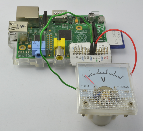
If you want to use almost the full range of a 5V volt meter, you will need a transistor to act as a switch for the PWM signal and a 1kΩ resistor to limit the current to the base of the transistor.
To make this recipe, you will need:
5V panel meter (“Miscellaneous”)
Breadboard and jumper wires (see “Prototyping Equipment”)
Two 1kΩ resistors (see “Resistors and Capacitors”)
Transistor 2N3904 (see “Transistors and Diodes”)
The breadboard layout for this is shown in Figure 10-15.
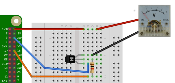
To test the volt meter, use the same program as you did for controlling the brightness of the LED in Recipe 10.9.
You will probably notice that the needle gives a steady reading at either end of the scale, but everywhere else it jitters a bit. This is a side effect of the way the PWM signals are generated. For a steadier result, you can use external PWM hardware like the 16-channel module used in Recipe 11.3.
For more information about how old-fashioned volt meters work, see Wikipedia.
For more information on using a breadboard and jumper wires with the Raspberry Pi, see Recipe 9.8.
Use the add_event_detect function of the RPi.GPIO library.
The upcoming example shows how you can attach an interrupt service routine to be triggered when a button is pressed.
Wire the switch onto a breadboard, as shown in Figure 10-16. Alternatively, you could use a Squid Button (Recipe 9.11).
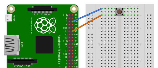
Open an editor (nano or IDLE) and paste in the following code. As with all the program examples in this book, you can download the program from the Code section of the Raspberry Pi Cookbook website, where it is called interrupts.py.
This example code continually updates a count in seconds and displays a message when the button is pressed:
importRPi.GPIOasGPIOimporttimeGPIO.setmode(GPIO.BCM)defmy_callback(channel):('You pressed the button')GPIO.setup(18,GPIO.IN,pull_up_down=GPIO.PUD_UP)GPIO.add_event_detect(18,GPIO.FALLING,callback=my_callback)i=0whileTrue:i=i+1(i)time.sleep(1)
Try running the program with superuser privileges—you should see something like this happen when you press the button:
$ sudo python interrupts.py 1 2 3 You pressed the button 4 You pressed the button 5 You pressed the button You pressed the button 6
You could detect when a button has been pressed or a GPIO input has changed by simply checking repeatedly in a loop; for example:
whileTrue:ifGPIO.input(18)==False:# put the code to be actioned heretime.sleep(0.1)
The disadvantage here is that you can’t do much else while you are checking for button presses. A second disadvantage is that if the button press is very quick, it could come and go before you can register it with the GPIO.input. This approach is called polling.
Interrupts work differently. They allow you to associate a function with one of the pins so that when the voltage at the input changes either from low to high or vice versa, you can trigger the function to be run.
You can see how this works in the preceding example program. First, define a function called my_callback that takes a single argument. This argument specifies the input that triggered the interrupt, allowing you to use the same handler function for a number of interrupts.
defmy_callback(channel):('You pressed the button')
In this case, the callback function just displays a message.
The line of code that does the actual linking is:
GPIO.add_event_detect(18,GPIO.FALLING,callback=my_callback)
The first parameter specifies the pin (18). The second can be GPIO.FALLING or GPIO.RISING. If this is set to FALLING, the function will only be called if the GPIO pin goes from high to low. This is the case in this example, as the switch pulls the input low against the internal pull-up resistor. If, on the other hand, the second argument is set to RISING, the function will only be called when the input goes from low to high (when the switch is released).
The event handler function does not stop the main counting loop while it runs; it actually runs in its own separate thread of execution.
Switches often bounce when pressed. This means they don’t always transition cleanly from open to closed but bounce between the two, possibly several times, making it appear that the button was pressed multiple times in very rapid succession when actually it was pressed only once.
If you keep pressing the button, you’ll probably see this reflected in the output as the message appearing more than once for one button press.
The library actually has an option to stop bounce from being a problem, by preventing the interrupt from being triggered again within a certain amount of time. To make use of this feature, just add the extra optional parameter bouncetime to the add_event_detect call. The value of bouncetime is in milliseconds.
GPIO.add_event_detect(18, GPIO.FALLING, callback=my_callback, bouncetime=100)
For more information on using switches with the Raspberry Pi, see Recipe 12.1.
Be sure to check out the accompanying video for this recipe at http://razzpisampler.oreilly.com.
Use PWM to control the width of pulses to a servo motor to change its angle. Although this will work, the PWM generated is not completely stable, so there will be a little bit of jitter with the servo. For an alternative solution that produces much more stable pulse timing using the ServoBlaster device driver software, see Recipe 11.2.
If you have an older Raspberry Pi 1, you should also power the servo from a separate 5V power supply because peaks in the load current are very likely to crash or overload the Raspberry Pi. If you have a Raspberry Pi B+ or newer, then improvements in the onboard voltage regulation mean that you may get away with powering small servos directly from the 5V pin on the GPIO port.
Figure 11-1 shows a small 9g servo (see “Miscellaneous”) working quite happily with a Raspberry Pi B+.
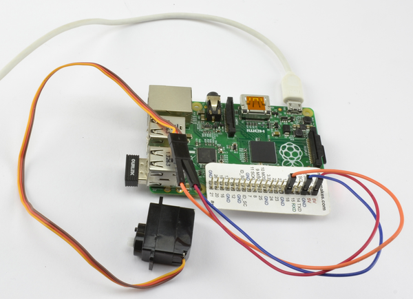
The leads of the servo are usually 5V wire as red, the ground brown, and the control lead orange. The 5V and ground leads are connected to the GPIO header 5V and GND pins, and the control lead is connected to pin 18. The connections are made with female-to-male header leads.
If you are using a separate power supply, then a breadboard is a good way of keeping all the leads together.
In this case, you will need:
5V servo motor (see “Miscellaneous”)
Breadboard and jumper wires (see “Prototyping Equipment”)
1kΩ resistor (see “Resistors and Capacitors”)
5V 1A power supply or 4.8V battery pack (see “Miscellaneous”)
The breadboard layout for this is shown in Figure 11-2.
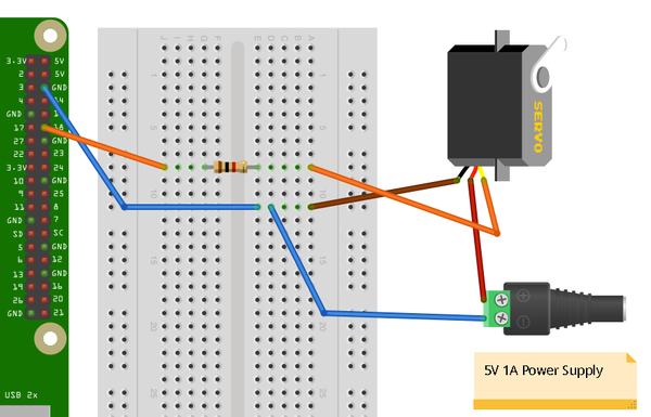
The 1kΩ resistor is not essential, but it does protect the GPIO pin from unexpectedly high currents in the control signal, which could occur if a fault developed on the servo.
You can, if you prefer, power the servo from a battery pack rather than a power supply. Using a four-cell AA battery holder with rechargeable batteries will provide around 4.8V and work well with a servo. Using four alkali AA cells to provide 6V will be fine for many servos, but check the datasheet of your servo to make sure it is OK with 6V.
The user interface for setting the angle of the servo is based on the gui_slider.py program intended for controlling the brightness of an LED (Recipe 10.9). However, you can modify it so that the slider sets the angle to be between 0 and 180 degrees (Figure 11-3).
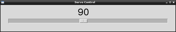
Open an editor (nano or IDLE) and paste in the following code. As with all the program examples in this book, you can also download the program from the Code section of the Raspberry Pi Cookbook website, where it is called servo.py.
Note that this program uses a graphical user interface, so you cannot run it from SSH.
You must run it from the windowing environment on the Pi itself or via remote control using VNC (Recipe 2.8) or RDP (Recipe 2.9). You also need to run it as superuser, so run it with the command sudo python servo.py:
fromTkinterimport*importRPi.GPIOasGPIOimporttimeGPIO.setmode(GPIO.BCM)GPIO.setup(18,GPIO.OUT)pwm=GPIO.PWM(18,100)pwm.start(5)classApp:def__init__(self,master):frame=Frame(master)frame.pack()scale=Scale(frame,from_=0,to=180,orient=HORIZONTAL,command=self.update)scale.grid(row=0)defupdate(self,angle):duty=float(angle)/10.0+2.5pwm.ChangeDutyCycle(duty)root=Tk()root.wm_title('Servo Control')app=App(root)root.geometry("200x50+0+0")root.mainloop()
Servo motors are used in remote control vehicles and robotics. Most servo motors are not continuous; that is, they cannot rotate all the way around but rather just over an angle of about 180 degrees.
The position of the servo motor is set by the length of a pulse. The servo expects to receive a pulse at least every 20 milliseconds. If that pulse is high for 1 millisecond, the servo angle will be zero; if it is 1.5 milliseconds, it will be at its center position; and if it is 2 milliseconds, it will be at 180 degrees (Figure 11-4).
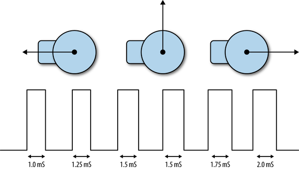
The example program sets the PWM frequency to 100 Hz, which will send a pulse to the servo every 10 milliseconds. The angle is converted into a duty cycle between 0 and 100.
If you have a lot of servos to control, or require greater stability and precision, then you can use a dedicated servo controller module, as described in Recipe 11.3.
Adafruit has developed another method of servo control.
For an alternative solution that produces much more stable pulse timing using the ServoBlaster device driver software, see Recipe 11.2.
Install the Servo Blaster device driver.
The Servo Blaster software crated by Richard Hurst uses Raspberry Pi CPU hardware to generate pulses with much more accurate timings than are possible using the RPi.GPIO library. Install this using the following commands and then reboot your Raspberry Pi.
git clone git://github.com/richardghirst/PiBits.git cd PiBits/ServoBlaster/user sudo make sudo make install
The program from Recipe 11.1 can be modified to use the Servo Blaster code. The modified program can be found in the file servo_blaster.py and assumes that the servo control pin is connected to GPIO 18.
fromTkinterimport*importosimporttimeservo_min=500# uSservo_max=2500# uSservo=2# GPIO 18defmap(value,from_low,from_high,to_low,to_high):from_range=from_high-from_lowto_range=to_high-to_lowscale_factor=float(from_range)/float(to_range)returnto_low+(value/scale_factor)defset_angle(angle):pulse=int(map(angle,0,180,servo_min,servo_max))command="echo {}={}us > /dev/servoblaster".format(servo,pulse)os.system(command)classApp:def__init__(self,master):frame=Frame(master)frame.pack()scale=Scale(frame,from_=0,to=180,orient=HORIZONTAL,command=self.update)scale.grid(row=0)defupdate(self,angle):set_angle(float(angle))root=Tk()root.wm_title('Servo Control')app=App(root)root.geometry("200x50+0+0")root.mainloop()
The user interface code is just the same as Recipe 11.1. The differences are in the set_angle function. The set_angle function first uses a utility function called map that converts the angle into a pulse duration using the constants servo_min and servo_max. set_angle. Then it constructs a command that will be run as if from the command line. The format of this line starts with the echo command followed by the servo number to be controlled, then an equals sign, and then a pulse duration in microseconds. This string part of the command will be directed to the device /dev/servoblaster. The servo will then adjust its angle.
When ServoBlaster, or more specifically, the service servo.d, is running, you will not be able to use the servo pins for anything and audio on the Raspberry Pi will not work. So when you need to use the pins for something else, use the following commands to disable ServoBlaster and then reboot your Pi.
$ sudo update-rc.d servoblaster disable $ sudo reboot
When your Raspberry Pi restarts, ServoBlaster will no longer have control of your pins. You can always turn ServoBlaster back on again using:
$ sudo update-rc.d servoblaster enable $ sudo reboot
The ServoBlaster driver is actually very powerful and can be configured to allow you to use pretty much all the GPIO pins to control servos. Its default setup defines eight GPIO pins to act as servo control pins. These are each given a channel number, as shown in Table 11-1.
| Servo Channel | GPIO Pin |
|---|---|
| 0 | 4 |
| 1 | 17 |
| 2 | 18 |
| 3 | 27 |
| 4 | 22 |
| 5 | 23 |
| 6 | 24 |
| 7 | 25 |
Connecting so many servos can result in jumper-lead spaghetti. A board like the MonkMakes Servo Six greatly simplifies the wiring of the servos to your Raspberry Pi.
You can find the full documentation for Servo Blaster at https://github.com/richardghirst/PiBits/tree/master/ServoBlaster.
If you do not need the precise timing of Servo Blaster, the RPi.GPIO library can also generate pulses for your servo, as described in Recipe 11.1.
Although the Servo Blaster code (see Recipe 11.2) allows you to control lots of servos accurately, it does not solve the problem of wiring up all those servos. You can do this with a breadboard, but it’s messy and wires are quite likely to become loose.
To make connection easy, use a servo motor HAT like the one shown in Figure 11-5.
This HAT allows you to control up to 16 servos or PWM channels using the I2C interface of the Raspberry Pi. The servos just plug straight into the HAT.
Power is supplied to the logic circuits of the module from the 3.3V connection of the Raspberry Pi. This is entirely separate from the power supply for the servo motors, which comes from an external 5V power adapter.
You can, if you prefer, power the servos from a battery pack rather than a power supply. Using a four-cell AA battery holder with rechargeable batteries provides around 4.8V and works well with most servos. Using four alkali AA cells to provide 6V will be fine for many servos, but check the datasheet of your servo to make sure it is OK with 6V.
The pin headers for connecting servos are conveniently arranged so that the servo lead fits directly onto the pins. Be careful to get them facing the right way.
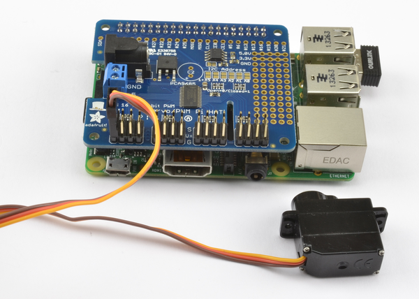
To use the Adafruit software for this module, you will need to set up I2C on the Raspberry Pi (Recipe 9.3).
The Adafruit library isn’t really a proper library that contains an installation script, but rather just a directory that contains a number of files. So, when using it, you need to be in the directory to which they are downloaded or your program will not find them.
To download all the Adafruit software libraries for Raspberry Pi, enter the following:
$ git clone https://github.com/adafruit/Adafruit-Raspberry-Pi-Python-Code.git $ cd Adafruit-Raspberry-Pi-Python-Code $ cd Adafruit_PWM_Servo_Driver
The last two lines set the current directory to the directory containing the code for PWM as well as an example program supplied by Adafruit, which you can run with the command:
$ sudo python Servo_Example.py
An alternative example next modifies the example program from Recipe 10.2 so that you can use a slider to set the servo position to be between 0 and 180 degrees. The program file must be saved in the Adafruit_PWM_Servo_Driver directory. The slider will change the servo positions of both channels 0 and 1 at the same time, so both servos will follow the position of the slider.
Open an editor (nano or IDLE) and paste in the following code. As with all the program examples in this book, you can also download the program from the Code section of the Raspberry Pi Cookbook website, where it is called servo_module.py. Note that this program uses a graphical user interface, so you can’t run it from SSH. You must run it from the windowing environment on the Pi itself or via remote control using VNC (Recipe 2.8) or RDP (Recipe 2.9).
fromTkinterimport*fromAdafruit_PWM_Servo_DriverimportPWMimporttimepwm=PWM(0x40)pwm.setPWMFreq(50)classApp:def__init__(self,master):frame=Frame(master)frame.pack()scale=Scale(frame,from_=0,to=180,orient=HORIZONTAL,command=self.update)scale.grid(row=0)defupdate(self,angle):pulse_len=int(float(angle)*500.0/180.0)+110pwm.setPWM(0,0,pulse_len)pwm.setPWM(1,0,pulse_len)root=Tk()root.wm_title('Servo Control')app=App(root)root.geometry("200x50+0+0")root.mainloop()
The first line after the import creates a new instance of PWM using the I2C address specified as its argument—in this case, 0×40. The module has solder pad connections that allow you to change the I2C address if this conflicts with another I2C device you are using, or you want to use more than one of these modules.
The next line sets the PWM frequency to 50 Hz, which will provide an update pulse every 20 milliseconds.
The line that actually sets the PWM for a particular channel is:
pwm.setPWM(0,0,pulse_len)
The first argument is the PWM channel whose duty cycle is to be changed. Each cycle of PWM is divided into 4,096 ticks, and the second argument is the tick at which the pulse should start. This will always be 0. The third argument is the tick at which the pulse should end. The constants of 500.0 and 110 in the following line were tweaked with a little trial and error to provide a standard servo with as close to 180 degrees of movement as possible:
pulse_len=int(float(angle)*500.0/180.0)+110
When selecting a power supply for this module, remember that a standard remote control servo can easily draw 400mA while it’s moving, and more if it’s under load. So if you plan to have a lot of large servos moving at the same time, you will need a big power adapter.
A Servo HAT is great if your Raspberry Pi is right by the servo motors, but if your servos are distant from where you want the Raspberry Pi to be, then Adafruit also sells a servo module (product ID 815) that has the same servo controller hardware as the servo HAT, but just has four pins to connect the I2C interface of the board to the Raspberry Pi’s I2C interface.
See the Adafruit documentation for its Raspberry Pi library.
You can use the same design as Recipe 10.5. It is, however, a good idea to place a diode across the motor to prevent voltage spikes from damaging the transistor or even the Raspberry Pi. The 1N4001 is a suitable diode for this. The diode has a stripe at one end, so make sure that this is facing the right way.
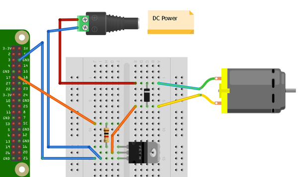
You will need:
3V to 12V DC motor
Breadboard and jumper wires (see “Prototyping Equipment”)
1kΩ resistor (see “Resistors and Capacitors”)
MOSFET Transistor FQP30N06L (see “Transistors and Diodes”)
Diode 1N4001 (see “Transistors and Diodes”)
Power supply with voltage to match the motor
To control the speed of the motor, you can download the program from the Code section of http://www.raspberrypicookbook.com, where it is called gui_slider.py. Note that this program uses a graphical user interface, so you can’t run it from SSH. You must run it from the windowing environment on the Pi itself or via remote control using VNC (Recipe 2.8) or RDP (Recipe 2.9).
If you are only using a low-power DC motor (less than 200mA), you can use a smaller (and cheaper) transistor such as the 2N3904 (see “Transistors and Diodes”). The breadboard layout to use a 2N3904 is shown in Figure 11-7.
You can probably get away with powering a small motor from the 5V supply line on the GPIO connector. If you find that the Raspberry Pi crashes, use an external power supply, as shown in Figure 11-6.
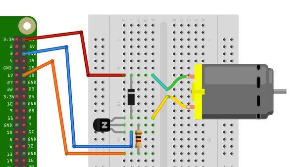
This design only controls the motor’s speed. It can’t control its direction. For that, you need to see Recipe 11.5.
For more information on using a breadboard and jumper wires with the Raspberry Pi, see Recipe 9.8.
Use an H-Bridge chip or module.
You have two recipes to choose from for controlling a motor. The first, the “DIY approach,” uses a solderless breadboard and a L293D chip. The second design uses a ready-made H-Bridge module from SparkFun, connecting it directly to the Raspberry Pi with jumper leads.
Both the L293D and the SparkFun module are capable of driving two motors without any extra hardware. The Discussion also mentions a few other options for controlling DC motors.
If you take the L293D route, you will need:
3V to 12V DC motor
Breadboard and jumper wires (male to female; see “Prototyping Equipment”)
L293D chip (see “Integrated Circuits”)
Power supply with voltage to match the motor
The breadboard layout is shown in Figure 11-8.
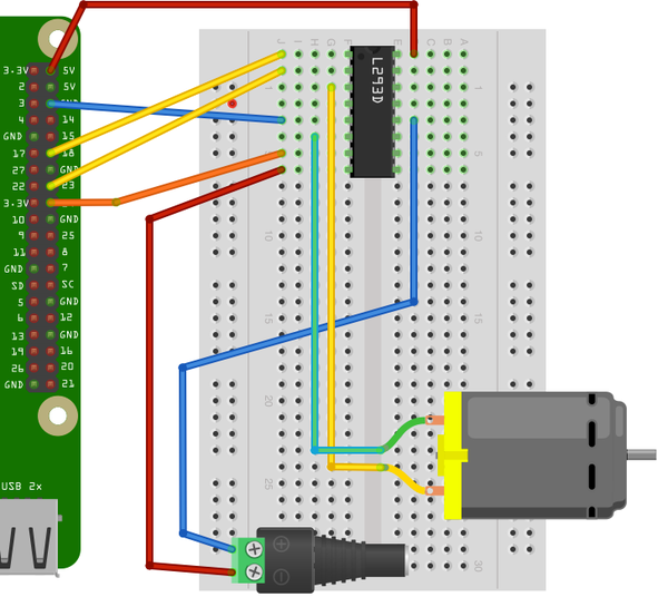
Make sure the chip is facing the right way: there is a notch in its top, which is the end that should be at the top of the breadboard.
If you decide to use the SparkFun motor controller, or a similar motor controller module, you will need the following:
3V to 12V DC motor
Jumper wires (female to female; see “Prototyping Equipment”)
Header pins (see “Integrated Circuits”)
SparkFun motor driver 1A dual (see “Modules”)
Power supply with voltage to match the motor
The layout is shown in Figure 11-9. Note that the motor shown is just a DC motor on its own. If the project is driving wheels, then you will typically use a gearmotor, which combines a motor and gearbox to reduce the RPM and increase the torque.
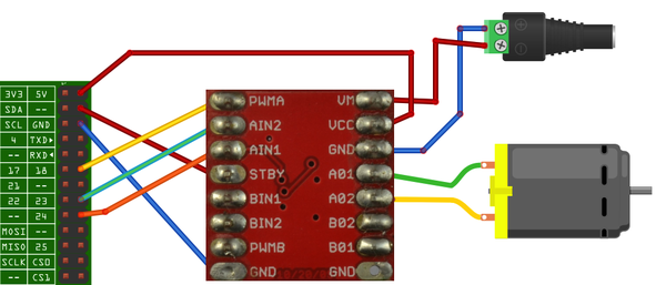
The motor controller module comes without header pins attached, so you will need to add these to the board before you get started. The connections are made using female-to-female header leads.
Figure 11-10 shows the module wired up to a small DC gearmotor, as per the wiring diagram of Figure 11-9.
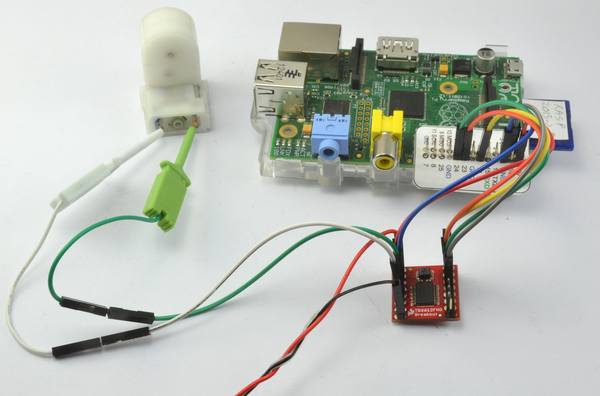
Whichever hardware option you decided upon, you can use the same program to try out the motor. This allows you to enter a letter f or r and then a single digit between 0 and 9. The motor will then either go forward or backward, at a speed specified by the digit—0 for stopped, 9 for full speed.
$ sudo python motor_control.py Command, f/r 0..9, E.g. f5 :f5 Command, f/r 0..9, E.g. f5 :f1 Command, f/r 0..9, E.g. f5 :f2 Command, f/r 0..9, E.g. f5 :r2
Open an editor (nano or IDLE) and paste in the following code. As with all the program examples in this book, you can also download the program from the Code section of the Raspberry Pi Cookbook website, where it is called motor_control.py. This program uses the command line, so you can run it from SSH.
If you’re using Python 3, change the command raw_input to just input:
importRPi.GPIOasGPIOimporttimeenable_pin=18in1_pin=23in2_pin=24GPIO.setmode(GPIO.BCM)GPIO.setup(enable_pin,GPIO.OUT)GPIO.setup(in1_pin,GPIO.OUT)GPIO.setup(in2_pin,GPIO.OUT)pwm=GPIO.PWM(enable_pin,500)pwm.start(0)defclockwise():GPIO.output(in1_pin,True)GPIO.output(in2_pin,False)defcounter_clockwise():GPIO.output(in1_pin,False)GPIO.output(in2_pin,True)whileTrue:cmd=raw_input("Command, f/r 0..9, E.g. f5 :")direction=cmd[0]ifdirection=="f":clockwise()else:counter_clockwise()speed=int(cmd[1])*10pwm.ChangeDutyCycle(speed)
Before you look at how the program operates, you need to understand a little more about how an H-Bridge works.
Figure 11-11 shows how one works, using switches rather than transistors or a chip. By reversing the polarity across the motor, an H-Bridge also reverses the direction the motor turns.
In Figure 11-11, S1 and S4 are closed and S2 and S3 are open. This allows current to flow through the motor, with terminal A being positive and terminal B being negative. If we were to reverse the switches so that S2 and S3 are closed and S1 and S4 are open, then B would be positive and A would be negative, and the motor would turn in the opposite direction.
However, you may have spotted a danger with this circuit. If by some chance S1 and S2 are both closed, then the positive supply will be directly connected to the negative supply and you will have a short-circuit. The same is true if S3 and S4 are both closed at the same time.

Although you can use individual transistors to make an H-Bridge, it is simpler to use an H-Bridge IC such as the L293D. This chip actually has two H-Bridges in it, so you can use it to control two motors.
The L293 has three control pins for each of the two motor control channels. The Enable pin just enables or disables the channel as a whole. In the example program, this is connected to a PWM output to control the speed of the motor. The other two pins (IN1 and IN2) control the direction in which the motor will be driven. You can see the use of these two control pins in the functions clockwise and counter_clockwise:
defclockwise():GPIO.output(in1_pin,True)GPIO.output(in2_pin,False)defcounter_clockwise():GPIO.output(in1_pin,False)GPIO.output(in2_pin,True)
If IN1 is high and IN2 is low, the motor will turn in one direction. If those two pins are reversed, the motor will turn in the opposite direction.
As an alternative to using an L293D on a breadboard, very low-cost modules are available from eBay that include a L293D on a PCB with screw terminals to attach motors and header pins to link directly to the Raspberry Pi GPIO connector. If you need a higher-power motor controller module, then you can find motor controller modules that operate on the same principles but at much higher currents, even up to 20A or more. Polulu has an impressive range of such motor controller boards.
The Adafruit Stepper Motor HAT (Recipe 11.8) and RaspiRobot board (Recipe 11.9) can also be used to control the speed and direction of a DC motor.
Check out the L293D datasheet and the SparkFun Motor Driver Module product page.
For more information on using a breadboard and jumper wires with the Raspberry Pi, see Recipe 9.8.
Use a ULN2803 Darlington driver chip on breadboard.
Stepper motors fit somewhere between DC motors and servo motors in the world of motor technologies. Like a regular DC motor, they can rotate continuously, but you can also very accurately position them by moving them a step at a time in either direction.
To make this recipe, you will need:
5V, five-pin unipolar stepper motor (see “Miscellaneous”)
ULN2803 Darlington driver IC (see “Integrated Circuits”)
Breadboard and jumper wires (see “Prototyping Equipment”)
Figure 11-12 shows the wiring diagram for using a ULN2803. Note that the chip can be used to drive two such motors. To drive a second stepper motor, you will need to connect four more control pins from the GPIO connector to pins 5 to 8 of the ULN2803, and connect the second motor’s four pins to pins 11 to 14 of the ULN2803.
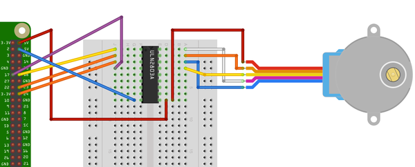
The 5V supply from the GPIO connector may work OK with a small stepper motor. If you experience problems with the Raspberry Pi crashing or need to use a bigger stepper motor, then use a separate supply for the power to the motor (pin 10 of the ULN2803).
Open an editor (nano or IDLE) and paste in the following code. As with all the program examples in this book, you can also download the program from the Code section of the Raspberry Pi Cookbook website, where it is called stepper.py. This program uses the command line, so you can run it from SSH.
If you’re using Python 3, change the command raw_input to just input:
importRPi.GPIOasGPIOimporttimeGPIO.setmode(GPIO.BCM)coil_A_1_pin=18coil_A_2_pin=23coil_B_1_pin=24coil_B_2_pin=17GPIO.setup(coil_A_1_pin,GPIO.OUT)GPIO.setup(coil_A_2_pin,GPIO.OUT)GPIO.setup(coil_B_1_pin,GPIO.OUT)GPIO.setup(coil_B_2_pin,GPIO.OUT)forward_seq=['1010','0110','0101','1001']reverse_seq=list(forward_seq)# to copy the listreverse_seq.reverse()defforward(delay,steps):foriinrange(steps):forstepinforward_seq:set_step(step)time.sleep(delay)defbackwards(delay,steps):foriinrange(steps):forstepinreverse_seq:set_step(step)time.sleep(delay)defset_step(step):GPIO.output(coil_A_1_pin,step[0]=='1')GPIO.output(coil_A_2_pin,step[1]=='1')GPIO.output(coil_B_1_pin,step[2]=='1')GPIO.output(coil_B_2_pin,step[3]=='1')whileTrue:set_step('0000')delay=raw_input("Delay between steps (milliseconds)?")steps=raw_input("How many steps forward? ")forward(int(delay)/1000.0,int(steps))set_step('0000')steps=raw_input("How many steps backwards? ")backwards(int(delay)/1000.0,int(steps))
When you run the program, you will be prompted for a delay between steps. This should be 2 or more. You will then be prompted for the number of steps in each direction:
$ sudo python stepper.py Delay between steps (milliseconds)?2 How many steps forward? 100 How many steps backwards? 100 Delay between steps (milliseconds)?10 How many steps forward? 50 How many steps backwards? 50 Delay between steps (milliseconds)?
Stepper motors use a cogged rotor and electromagnets to nudge the wheel around a step at a time (Figure 11-13). Note that the colors of the leads will vary.
Energizing the coils in a certain order drives the motor around. The number of steps that the stepper motor has in a 360-degree rotation is actually the number of teeth on the rotor.
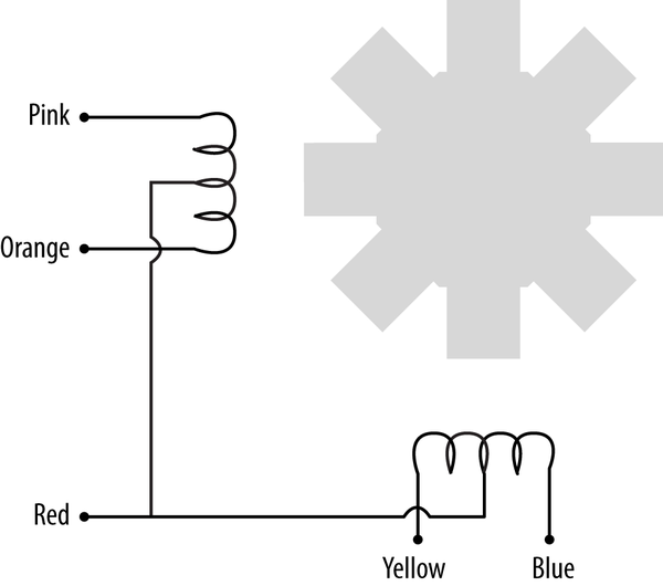
The example program uses a list of strings to represent each of the four energization stages that make up a single step:
forward_seq=['1010','0110','0101','1001']
The sequence for rotating the motor in the opposite direction is just the reverse of the sequence for moving forward.
You can use the forward and backward functions in your programs to step the motor back and forth. The first argument to either function is the delay in milliseconds between each part of the step sequence. This minimum value for this depends on the motor you use. If it’s too small, the motor will not turn. Typically, two milliseconds or more will be fine. The second parameter is the number of steps to take.
defforward(delay,steps):foriinrange(steps):forstepinforward_seq:set_step(step)time.sleep(delay)
The forward function has two nested for loops. The outer one repeats for the number of steps and the inner one iterates over the sequence of motor activations, calling setStep for each in sequence.
defset_step(step):GPIO.output(coil_A_1_pin,step[0]=='1')GPIO.output(coil_A_2_pin,step[1]=='1')GPIO.output(coil_B_1_pin,step[2]=='1')GPIO.output(coil_B_2_pin,step[3]=='1')
The set_step function sets each of the control pins to high or low, depending on the pattern supplied as its argument.
The main loop sets the step to 0000 between moving forward and backward, to set the outputs all to zero when the motor is not actually turning. Otherwise, one of the coils may be left on, causing the motor to draw current unnecessarily.
If you have a four-wire bipolar stepper motor, see Recipe 11.7.
For more information on stepper motors, the different types, and how they work, see Wikipedia, where you will also find a nice animated explanation of the activation pattern for driving the motor.
For information on using servo motors, see Recipe 11.1; for controlling DC motors, see Recipes 7.16 and 7.18.
For more information on using a breadboard and jumper wires with the Raspberry Pi, see Recipe 9.8.
Use a L293D H-Bridge driver chip. An H-Bridge is required to drive a bipolar stepper motor because, as the word bipolar suggests, the direction of current across the windings needs to be reversed, rather like driving a DC motor in both directions (see Recipe 11.5).
To make this recipe, you will need:
12V, four-pin bipolar stepper motor (see “Miscellaneous”)
L293D H-Bridge IC (see “Integrated Circuits”)
Breadboard and jumper wires (see “Prototyping Equipment”)
The motor used here, a 12V, is somewhat larger than the previous unipolar stepper motor example. The power for the motor itself is therefore supplied from an external power supply rather than from the Raspberry Pi. See the wiring diagram in Figure 11-14.
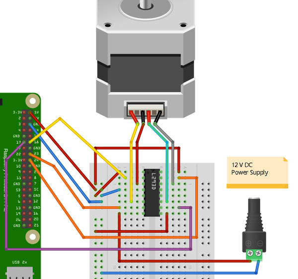
You can use the exact same stepper.py program to control this stepper (see Recipe 11.6). The design uses both H-Bridges of the L293D, so you need one of these chips for each motor you want to control.
If the type of stepper motor you have is a five-wire unipolar stepper motor, see Recipe 11.6.
For more information on stepper motors—the different types and how they work—see Wikipedia, where you will also find a nice animated explanation of the activation pattern for driving the motor.
For information on using servo motors, see Recipe 11.1 and for controlling DC motors, see Recipes 7.16 and 7.18.
For more information on using a breadboard and jumper wires with the Raspberry Pi, see Recipe 9.8.
You can also drive a stepper motor by using the RasPiRobot board (Recipe 11.9).
Use an Adafruit Stepper Motor HAT (Figure 11-15).
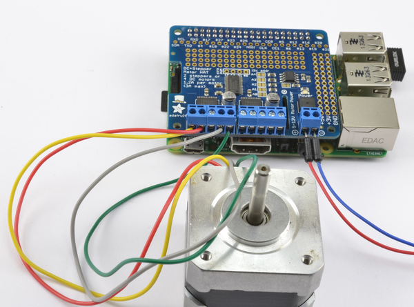
This board is capable of driving two bipolar stepper motors. Figure 11-15 shows the board with one bipolar stepper motor with one coil connected to the M1 terminals and the other coil to the M2 terminals. The power for the motors is supplied separately at the screw terminals on the right of Figure 11-15.
This HAT uses I2C so make sure that you have I2C enabled (Recipe 9.3).
To make it easy to use the HAT, Adafruit has written a Python library. To install it, enter the following commands:
$ git clone https://github.com/adafruit/Adafruit-Motor-HAT-Python-Library.git $ sudo apt-get install python-dev $ cd Adafruit-Motor-HAT-Python-Library/ $ sudo python setup.py install
The library includes a few examples, so change directory and then run the basic example using the commands:
$ cd examples $ sudo python StepperTest.py
If you followed recipe Recipe 9.20 to make your own HAT and enabled the I2C bus 0 as described there, then you will need to reverse the change to /boot/config.txt because the Adafruit autodetects the I2C bus to use and will detect the wrong one if bus 0 is enabled.
In /boot/config.txt, delete or uncomment out the line:
dtparam=i2c_vc=on
Once this is done, reboot your Raspberry Pi.
When you run the program, the motor will start to turn and the program will loop round four different modes of stepping. You might like to try the simple example below to control your stepper motor.
Open an editor (nano or IDLE) and paste in the following code. As with all the program examples in this book, you can also download the program from the Code section of the Raspberry Pi Cookbook website, where it is called stepper_hat.py. This program uses the command line, so you can run it from SSH.
fromAdafruit_MotorHATimportAdafruit_MotorHATimporttimeHAT=Adafruit_MotorHATstepper_hat=Adafruit_MotorHAT()stepper=stepper_hat.getStepper(200,1)# 200 steps/rev, port 1 (M1, M2)try:whileTrue:speed=input("Enter stepper speed (rpm) ")stepper.setSpeed(speed)steps_forward=input("Steps forward ")stepper.step(steps_forward,HAT.FORWARD,HAT.SINGLE)steps_forward=input("Steps reverse ")stepper.step(steps_forward,HAT.BACKWARD,HAT.SINGLE)finally:("cleaning up")stepper_hat.getMotor(1).run(HAT.RELEASE)
After importing the Adafruit_MotorHAT module, it is assigned the name HAT just to reduce the verbosity of the code on the lines that follow this.
The try/finally block is used to make sure that the power to the coils are released when the program is stopped using Ctrl-C.
For a discussion of the HAT standard and how to make your own HAT, see Recipe 9.20.
For more information on using this HAT and its accompanying library, see https://learn.adafruit.com/adafruit-dc-and-stepper-motor-hat-for-raspberry-pi/.
To use a L293D to control a stepper motor, see Recipe 11.7; and for a RaspiRobot board, see Recipe 11.9.
Be sure to check out the accompanying video for this recipe at http://razzpisampler.oreilly.com.
Use a RaspiRobot board Version 3.
The RaspiRobot board uses the power supply directly from its screw terminals as the supply to the motor and regulates that same supply down to 5V to drive the Raspberry Pi. So in this case, the 12V power will be supplying both the 12V stepper motor and the Raspberry Pi.
If you are using an earlier version of the RasPiRobot board (version 1 or 2), then do not power the Raspberry Pi through its USB connection at the same time as you power it through the RasPiRobot board.
There is no problem powering it through both in version 3 of the board.
Connect the stepper motor and power supply to the RaspiRobot board as shown in Figure 11-16. The wire colors for the Adafruit 12V stepper motor are, in order from left to right: yellow, red, gray, and green.
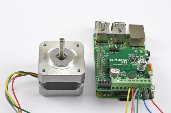
Before you can run the program, you will need to install the library for the RaspiRobot V3 using the following commands:
$ git clone https://github.com/simonmonk/raspirobotboard3.git $ cd raspirobotboard3/python $ sudo python setup.py install
Open an editor (nano or IDLE) and paste in the following code. As with all the program examples in this book, you can also download the program from the Code section of the Raspberry Pi Cookbook website, where it is called stepper_rrb.py. This program uses the command line, so you can run it from SSH.
If you’re using Python 3, change the command raw_input to just input:
fromrrb3import*importtimerr=RRB3(12.0,12.0)# battery, motortry:whileTrue:delay=raw_input("Delay between steps (milliseconds)?")steps=raw_input("How many steps forward? ")rr.step_forward(int(delay)/1000.0,int(steps))steps=raw_input("How many steps backwards? ")rr.step_reverse(int(delay)/1000.0,int(steps))finally:GPIO.cleanup()
You will find that there is a minimum value of "Delay between steps", below which the motor will just judder rather than turn.
You can find full documentation for the RaspiRobot board and other projects that use it at the RaspiRobot website.
To drive a stepper motor using a L293D on a breadboard, see Recipe 11.7.
Use a RaspiRobot board V3 as an interface board to the Raspberry Pi to control two motors and a robot chassis kit such as the Magician Chassis.
To make this recipe, you will need:
RaspiRobot board V3 (see “Modules”)
Gearmotor chassis such as the Magician Chassis (see “Miscellaneous”)
6×AA battery holder (see “Miscellaneous”)
USB WiFi adapter
You can also buy a complete kit of parts for building this rover as the MonkMakes RaspiRobot Rover Kit.
The first step in building the robot is to assemble the chassis. Most low-cost gearmotor chassis are supplied with a four-cell AA battery holder, but to provide power to the Raspberry Pi, you really need a six-cell battery holder. When you get to that part of the instructions supplied with the chassis, use a 6×AA battery box.
Follow the wiring instructions as shown in Figure 11-17.
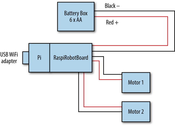
The battery pack will supply power to the RaspiRobot board, which in turn supplies 5V to the Raspberry Pi. So only one power supply is required.
The finished rover should look something like Figure 11-18, which also has a rangefinder on the front for good measure.
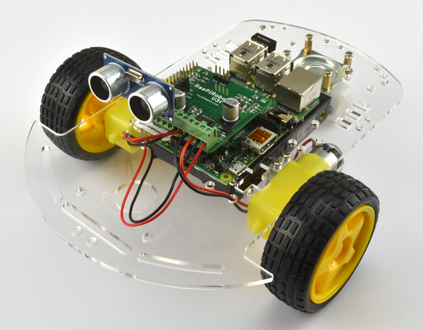
To drive the robot, you are going to use a control program that allows you to steer the rover using keys on a laptop or other computer connected to your Raspberry Pi over SSH. If you have not already done so, set up your Raspberry Pi to use WiFi and SSH, using Recipe 2.5 and Recipe 2.7.
Open an editor (nano or IDLE) and paste in the following code. As with all the program examples in this book, you can also download the program from the Code section of the Raspberry Pi Cookbook website, where it is called rover.py.
fromrrb3import*importsysimportttyimporttermiosrr=RRB3(9.0,6.0)# battery, motorUP=0DOWN=1RIGHT=2LEFT=3("Use the arrow keys to move the robot")("Press Ctrl-C to quit the program")# These functions allow the program to read your keyboarddefreadchar():fd=sys.stdin.fileno()old_settings=termios.tcgetattr(fd)try:tty.setraw(sys.stdin.fileno())ch=sys.stdin.read(1)finally:termios.tcsetattr(fd,termios.TCSADRAIN,old_settings)ifch=='0x03':raiseKeyboardInterruptreturnchdefreadkey(getchar_fn=None):getchar=getchar_fnorreadcharc1=getchar()iford(c1)!=0x1b:returnc1c2=getchar()iford(c2)!=0x5b:returnc1c3=getchar()returnord(c3)-65# 0=Up, 1=Down, 2=Right, 3=Left arrows# This will control the movement of your robot and display on your screentry:whileTrue:keyp=readkey()ifkeyp==UP:rr.forward(1)'forward'elifkeyp==DOWN:rr.reverse(1)'backward'elifkeyp==RIGHT:rr.right(1)'clockwise'elifkeyp==LEFT:rr.left(1)'anti clockwise'elifkeyp==LEFT:rr.left(1)'anti clockwise'eliford(keyp)==3:breakexceptKeyboardInterrupt:GPIO.cleanup()
To be able to intercept keypresses, this program uses the termios library and the two functions readchar and readkey.
After the import commands, a new instance of RRB3 is created. The two parameters to this are the battery voltage and the motor voltage (in this case, 9V and 6V respectively). If your chassis has different voltage motors, then change the second parameter.
The main loop just checks for keypresses and then sends the appropriate commands of forward, reverse, left, or right to the RRB3 library.
You can make the rover more interesting by adding peripherals to it. You could, for example, attach a webcam and set up web streaming so that your roving robot becomes a roving spycam (Recipe 4.5).
The RRB3 library also supports the HC-SR04 rangefinders that can be plugged into a socket on the RaspiRobot board V3. You can use this to detect obstacles, and you will find example software for this in the RRB3 library.
You can find out more about the RaspiRobot board and the RRB3 library on GitHub.
In this chapter, you look at recipes for using digital inputs, such as switches and keypads. This chapter also covers modules that have a digital output that can be connected to a Raspberry Pi GPIO input.
Most of the recipes require the use of a solderless breadboard and jumper wires (see Recipe 9.8).
Be sure to check out the accompanying video for this recipe at http://razzpisampler.oreilly.com.
Connect a switch to a GPIO pin and use the RPi.GPIO library in your Python program to detect the button press.
To make this recipe, you will need:
Breadboard and jumper wires (see “Prototyping Equipment”)
Tactile push switch (see “Miscellaneous”)
Figure 12-1 shows how to connect a tactile push switch using a breadboard and jumper wires.
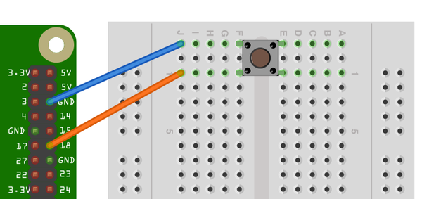
An alternative to using a breadboard and tactile switch is to use a Squid Button (Figure 12-2). This is a push switch with female header leads soldered to the end, which can be connected directly to a the GPIO connector (Recipe 9.11).

Open an editor (nano or IDLE) and paste in the following code. As with all the program examples in this book, you can also download the program from the Code section of the Raspberry Pi Cookbook website, where it is called switch.py.
This example code displays a message when the button is pressed:
importRPi.GPIOasGPIOimporttimeGPIO.setmode(GPIO.BCM)GPIO.setup(18,GPIO.IN,pull_up_down=GPIO.PUD_UP)whileTrue:input_state=GPIO.input(18)ifinput_state==False:('Button Pressed')time.sleep(0.2)
You will need to run the program as superuser:
pi@raspberrypi ~ $ sudo python switch.py Button Pressed Button Pressed Button Pressed Button Pressed
You will notice that the switch is wired so that when it is pressed, it will connect pin 18 configured as an input to GND. The input pin is normally pulled up to 3.3V by the optional argument pull_up_down=GPIO.PUD_UP in GPIO.setup. This means that when you read the input value using GPIO.input, False will be returned if the button is pressed. This is a little counterintuitive.
Each GPIO pin has software-configurable pull-up and pull-down resistors. When using a GPIO pin as an input, you can configure these resistors so that one, either, or neither of the resistors is enabled, using the optional pull_up_down parameter to GPIO.setup. If this parameter is omitted, then neither resistor will be enabled. This leaves the input floating, which means that its value cannot be relied upon and it will drift between high and low depending on what it picks up in the way of electrical noise.
If it is set to GPIO.PUD_UP, the pull-up resistor is enabled; if it is set to GPIO.PUD_DOWN, the pull-down resistor is enabled.
You might expect the push switch to have just two connections, which are either open or closed. While some of these tactile push switches do have just two connections, most have four. Figure 12-3 shows how these connections are arranged.

Actually, there are really only two electrical connections because inside the switch package, pins B and C are connected together, as are A and D.
For more information on using a breadboard and jumper wires with the Raspberry Pi, see Recipe 9.8.
To use a switch to trigger an interrupt, see Recipe 10.13.
To debounce a switch, see Recipe 12.5.
To use external pull-up or pull-down resistors, see Recipe 12.6.
Record the last state of the button and invert that value each time the button is pressed.
The following example toggles an LED on and off as you press the switch.
To make this recipe, you will need:
Breadboard and jumper wires (see “Prototyping Equipment”)
Tactile push switch (see “Miscellaneous”)
LED (see “Opto-Electronics”)
470Ω resistor (see “Resistors and Capacitors”)
Figure 12-4 shows how to connect a tactile push switch and LED, using a breadboard and jumper wires.
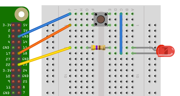
In addition to the male-to-female jumper wires connecting the Raspberry Pi to the breadboard, you will also need one male-to-male jumper wire or solid core wire.
Open an editor (nano or IDLE) and paste in the following code. As with all the program examples in this book, you can also download the program from the Code section of the Raspberry Pi Cookbook website, where it’s called switch_on_off.py:
importRPi.GPIOasGPIOimporttimeGPIO.setmode(GPIO.BCM)switch_pin=18led_pin=23GPIO.setup(switch_pin,GPIO.IN,pull_up_down=GPIO.PUD_UP)GPIO.setup(led_pin,GPIO.OUT)led_state=Falseold_input_state=True# pulled-upwhileTrue:new_input_state=GPIO.input(switch_pin)ifnew_input_state==Falseandold_input_state==True:led_state=notled_stateold_input_state=new_input_stateGPIO.output(led_pin,led_state)
The variable led_state contains the current state of the LED (True for on and False for off). Whenever the button is pressed, the following line is run:
led_state=notled_state
The not command inverts the value of led_state, so if led_state is True, it becomes False and vice versa.
The variable old_input_state is used to remember the button position so that a button press is defined as occurring only when the input state changes from being True (switch not pressed) to False (switch pressed).
You will find that sometimes when you press the button, it does not seem to toggle the LED. This is because of switch bounce. You can find other techniques for avoiding switch bounce in Recipe 12.5.
Use the switch as you would a tactile push switch (Recipe 12.1): just connect the center and one end contact (Figure 12-5).
To make this recipe, you will need:
Breadboard and jumper wires (see “Prototyping Equipment”)
Miniature toggle or slide switch (see “Miscellaneous”)
The same code you used in Recipe 12.1 works with this arrangement.
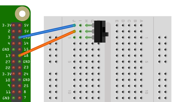
These type of slide switches are useful because you can see the position they are set to without the need for some additional indicator like an LED. However, they are more fragile and a little more expensive than the tactile push switches that are used more and more in consumer electronics because they can sit behind a nicer-looking plastic button.
To use a three-position switch, with a center-off position, see Recipe 12.4.
Connect the switch to two GPIO pins, as shown in Figure 12-6, and use the RPi.GPIO library in your Python program to detect the position of the switch.
To make this recipe, you will need:
Breadboard and jumper wires (see “Prototyping Equipment”)
Miniature center-off three-position toggle switch (see “Miscellaneous”)
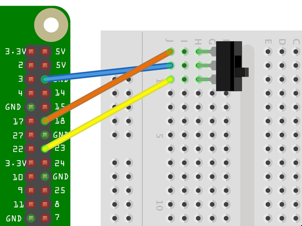
The common (center) connection of the switch is connected to ground, and each of the two ends of the switch are connected to a GPIO pin with the internal pull-up resistor enabled.
Open an editor (nano or IDLE) and paste in the following code. As with all the program examples in this book, you can also download the program from the Code section of the Raspberry Pi Cookbook website, where it is called switch_2_pos.py:
importRPi.GPIOasGPIOimporttimeGPIO.setmode(GPIO.BCM)top_input=18bottom_input=23GPIO.setup(top_input,GPIO.IN,pull_up_down=GPIO.PUD_UP)GPIO.setup(bottom_input,GPIO.IN,pull_up_down=GPIO.PUD_UP)switch_position="unknown"whileTrue:top_state=GPIO.input(top_input)bottom_state=GPIO.input(bottom_input)new_switch_position="unknown"iftop_state==False:new_switch_position="up"elifbottom_state==False:new_switch_position="down"else:new_switch_position="center"ifnew_switch_position!=switch_position:switch_position=new_switch_position(switch_position)
Run the program, and as you move the switch from top to center to bottom, the position of the switch will be reported every time it changes:
$ sudo python switch_3_pos.py up center down
The program sets up two inputs with pull-up resistors enabled. The variable switch_position is used to record the current position of the switch.
Inside the loop, both GPIO inputs are read and the three conditions of the if, elif, and else structure determine the position of the switch, assigning the value to a variable called new_switch_position. If this differs from the previous value, then the switch position is printed.
You will find a wide range of types of toggle switches. Some will be described as DPDT, SPDT, SPST, or SPST, momentary on, and so on. The meaning of these letters is as follows:
D: Double
S: Single
P: Pole
T: Throw
A DPDT switch is double pole, double throw. The word pole refers to the number of separate switch contacts that are controlled from the one mechanical lever. So, a double pole switch can switch two things on and off independently. A single throw switch can only open or close a single contact (or two contacts if it is double pole). However, a double throw switch can connect the common contact to one of two other contacts.
Figure 12-7 shows the most common types of switch.
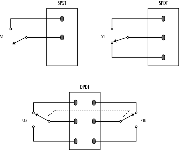
For more information on how if statements work, see Recipe 5.18. For the most basic switch recipe, see Recipe 12.1.
There are a number of solutions to this problem. To explore them, build the breadboard setup from Recipe 12.2.
The original code for this example, without any attempt at debouncing, looks like this:
importRPi.GPIOasGPIOimporttimeGPIO.setmode(GPIO.BCM)switch_pin=18led_pin=23GPIO.setup(switch_pin,GPIO.IN,pull_up_down=GPIO.PUD_UP)GPIO.setup(led_pin,GPIO.OUT)led_state=Falseold_input_state=True# pulled-upwhileTrue:new_input_state=GPIO.input(switch_pin)ifnew_input_state==Falseandold_input_state==True:led_state=notled_stateold_input_state=new_input_stateGPIO.output(led_pin,led_state)
The problem is that if the switch contacts bounce, it is just as if the switch were pressed more than once in very rapid succession. If they bounce an odd number of times, then things will seem to be OK. But if they bounce an even number of times, the two events will toggle the LED on and then straight back off again.
You need to ignore any changes after the switch is pressed for a short amount of time, while the switch finishes bouncing.
The quick and easy way to do this is to introduce a short sleep after the button press is detected by adding a time.sleep command of, say, 0.2 seconds. This delay is probably much higher than necessary, strictly speaking. You may find that you can reduce this considerably.
importRPi.GPIOasGPIOimporttimeGPIO.setmode(GPIO.BCM)switch_pin=18led_pin=23GPIO.setup(switch_pin,GPIO.IN,pull_up_down=GPIO.PUD_UP)GPIO.setup(led_pin,GPIO.OUT)led_state=Falseold_input_state=True# pulled-upwhileTrue:new_input_state=GPIO.input(switch_pin)ifnew_input_state==Falseandold_input_state==True:led_state=notled_statetime.sleep(0.2)old_input_state=new_input_stateGPIO.output(led_pin,led_state)
This solution is OK in most situations, but you might also consider using the switch pin with an interrupt (Recipe 10.13).
Switch bouncing occurs on most switches and can be quite severe on some switches, as the oscilloscope trace in Figure 12-8 shows.

You can see that there is contact bounce both as the switch closes and when it is released. Most switches are not as bad as this one.
For the basics of connecting a button, see Recipe 12.1.
The Squid Button library debounces button presses, using a similar approach to that described here; see Recipe 9.11 for details about the Squid Button.
The internal pull-up resistors are quite weak (about 40kΩ). If you run a long lead to the switch or operate in an electrically noisy environment, you may get false triggerings on the digital input. You can overcome this by turning off the internal pull-up and pull-down resistors and using an external pull-up resistor.
Figure 12-9 shows the use of an external pull-up resistor.
To test out this hardware, you can use the program switch.py; see Recipe 12.1.
The lower the resistance of the resistor, the longer the range of your switch. However, when you press the button, a current flows from 3.3V through the resistor to ground. A 100Ω resistor draws a current of 3.3V/100Ω = 33mA. This is within the safe limit for the 3.3V supply of 50mA or a Raspberry Pi 1, so don’t use a lower value than this if you have an older Raspberry Pi. If you are using a newer 40-pin GPIO Raspberry Pi, then you could drop this value even further to perhaps 47Ω.
In almost all cases, a 1kΩ resistor will provide a long range with no problems.
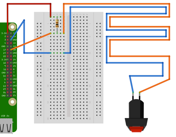
For the basics of connecting a button, see Recipe 12.1.
Use a rotary (quadrature encoder) connected to two GPIO pins, as shown in Figure 12-10.
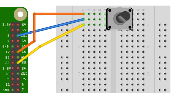
To make this recipe, you will need:
Breadboard and jumper wires (see “Prototyping Equipment”)
Rotary encoder (quadrature type; see “Miscellaneous”)
This type of rotary encoder is called a quadrature encoder, and it behaves like a pair of switches. The sequence in which they open and close as the rotary encoder’s shaft is turned determines the direction of rotation.
The rotary encoder shown has the center lead as the common lead and the two leads on either side as A and B. Not all rotary encoders use this layout, so check the pinout on the datasheet for the rotary encoder that you are using. The issue is often confused further because many rotary encoders include a push switch, which will have a separate pair of contacts.
Open an editor (nano or IDLE) and paste in the following code. As with all the program examples in this book, you can also download the program from the Code section of the Raspberry Pi Cookbook website, where it is called rotary_encoder.py.
importRPi.GPIOasGPIOimporttimeGPIO.setmode(GPIO.BCM)input_A=18input_B=23GPIO.setup(input_A,GPIO.IN,pull_up_down=GPIO.PUD_UP)GPIO.setup(input_B,GPIO.IN,pull_up_down=GPIO.PUD_UP)old_a=Trueold_b=Truedefget_encoder_turn():# return -1, 0, or +1globalold_a,old_bresult=0new_a=GPIO.input(input_A)new_b=GPIO.input(input_B)ifnew_a!=old_aornew_b!=old_b:ifold_a==0andnew_a==1:result=(old_b*2-1)elifold_b==0andnew_b==1:result=-(old_a*2-1)old_a,old_b=new_a,new_btime.sleep(0.001)returnresultx=0whileTrue:change=get_encoder_turn()ifchange!=0:x=x+change(x)
The test program simply counts up as you turn the rotary encoder clockwise, and counts down when you rotate it counterclockwise.
pi@raspberrypi ~ $ sudo python rotary_encoder.py 1 2 3 4 5 6 7 8 9 10 9 8 7 6 5 4
Figure 12-11 shows the sequence of pulses that you will get from the two contacts, A and B. You can see that the pattern repeats itself after four steps (hence the name quadrature encoder).

When rotating clockwise (left to right in Figure 12-11), the sequence will be:
| Phase | A | B |
|---|---|---|
|
1 |
0 |
0 |
|
2 |
0 |
1 |
|
3 |
1 |
1 |
|
4 |
1 |
0 |
When rotating in the opposite direction, the sequence of phases will be reversed.
| Phase | A | B |
|---|---|---|
|
4 |
1 |
0 |
|
3 |
1 |
1 |
|
2 |
0 |
1 |
|
1 |
0 |
0 |
The Python program listed previously implements the algorithm for determining the rotation direction in the function get_encoder_turn. The function will return 0 (if there has been no movement), 1 for a rotation clockwise, or -1 for a rotation counterclockwise. It uses two global variables, old_a and old_b, to store the previous states of the switches A and B. By comparing them with the newly read values, it can determine (using a bit of clever logic) which direction the encoder is turning.
The sleep period of 1 millisecond is to ensure that the next new sample does not occur too soon after the previous sample; otherwise, the transitions can give false readings.
The test program should work reliably no matter how fast you twiddle the knob on the rotary encoder; however, try to avoid doing anything time-consuming in the loop, or you may find that turn steps are missed.
You can also measure the rotated position of a knob by using a variable resistor with the step response method (Recipe 13.1) or by using an analog-to-digital converter (Recipe 13.5).
Keypads are arranged in rows and columns, with a push switch on the intersection of each row or column. To find out which key is pressed, you first connect all the row and column connections to Raspberry Pi GPIO pins. So, for a 4×3 keypad, you will need four + three pins. By scanning each column in turn (setting it to output high) and reading the value of each of the row inputs, you can determine which (if any) key is pressed.
Note that keypads show considerable variation in their pinouts.
To make this recipe, you will need:
Breadboard and jumper wires (see “Prototyping Equipment”)
4×3 keypad (see “Miscellaneous”)
Seven male header pins (see “Miscellaneous”)
Figure 12-12 shows the wiring diagram for the project using the SparkFun keypad listed in “Miscellaneous”. The keypad is supplied without header pins, which must be soldered onto the keypad.
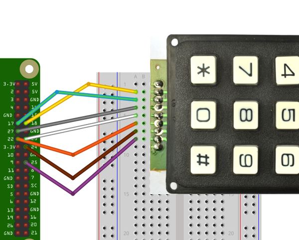
Open an editor (nano or IDLE) and paste in the following code. As with all the program examples in this book, you can also download the program from the Code section of the Raspberry Pi Cookbook website, where it is called keypad.py.
Before you run the program, make sure that the row and column pins are correct for the keypad that you are using, and if necessary change the values in the variables rows and cols. If you do not do this, then it is possible that pressing a key could short one GPIO output to another, where one is high and the other is low. This would likely damage your Raspberry Pi.
The row and columns defined here are correct for the SparkFun keypad listed in “Miscellaneous” in Appendix A. The first row is connected to GPIO pin 17, the second to 25, and so on. The wiring of the row and column to the keypad connector is illustrated in Figure 12-13.

importRPi.GPIOasGPIOimporttimeGPIO.setmode(GPIO.BCM)rows=[17,25,24,23]cols=[27,18,22]keys=[['1','2','3'],['4','5','6'],['7','8','9'],['*','0','#']]forrow_pininrows:GPIO.setup(row_pin,GPIO.IN,pull_up_down=GPIO.PUD_DOWN)forcol_pinincols:GPIO.setup(col_pin,GPIO.OUT)defget_key():key=0forcol_num,col_pininenumerate(cols):GPIO.output(col_pin,1)forrow_num,row_pininenumerate(rows):ifGPIO.input(row_pin):key=keys[row_num][col_num]GPIO.output(col_pin,0)returnkeywhileTrue:key=get_key()ifkey:(key)time.sleep(0.3)
You must run the program with superuser privileges, as it accesses the GPIO. You can see the trace from the program pressing each key in turn.
pi@raspberrypi ~ $ sudo python keypad.py 1 2 3 4 5 6 7 8 9 * 0 #
The keys variable contains a map of the key name for each row and column position. You can customize this for your keypad.
Because there are quite a lot of pins to initialize as inputs or outputs, both the row and column pins are initialized in loops.
All the real action takes place in the get_key function. This enables each column in turn, by setting it to high. An inner loop then tests each of the rows in turn. If one of the rows is high, then the key name corresponding to that row and column is looked up in the keys array. If no keypress is detected, then the default value of key (0) is returned.
The main while loop just gets the key value and prints it. The sleep command just slows down the output.
An alternative to adding a keyboard is simply to use a USB keypad. That way you can just catch keystrokes as described in Recipe 12.11.
Use a passive infrared (PIR) motion detector module.
To make this recipe, you will need:
Female-to-female jumper wires (see “Prototyping Equipment”)
PIR motion detector module (see “Modules”)
Figure 12-14 shows how the sensor module is wired. This module expects a power supply of 5V and has an output of 3.3V, making it ideal for use with a Raspberry Pi.
Make sure that the PIR module you use has a 3.3V output. If it has 5V output, you will need to use a pair of resistors to reduce this to 3.3V (see Recipe 13.6).
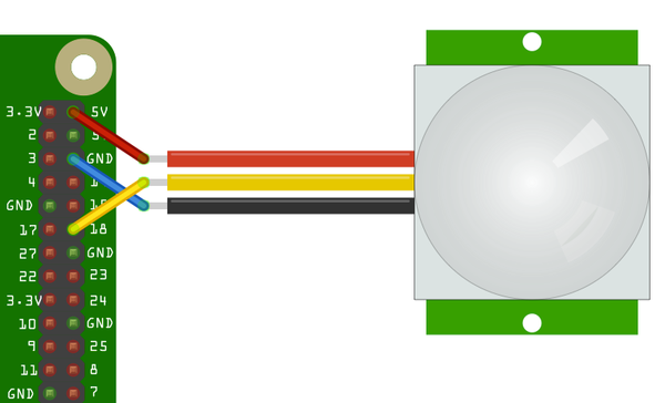
Open an editor (nano or IDLE) and paste in the following code. As with all the program examples in this book, you can also download the program from the Code section of the Raspberry Pi Cookbook website, where it is called pir.py.
importRPi.GPIOasGPIOimporttimeGPIO.setmode(GPIO.BCM)GPIO.setup(18,GPIO.IN)whileTrue:input_state=GPIO.input(18)ifinput_state==True:('Motion Detected')time.sleep(1)
The program simply prints out the state of the GPIO input 18.
$ sudo python pir.py Motion Detected Motion Detected
Once triggered, the output of the PIR sensor will stay high for a little while. You can adjust this using one of the trimpots on its circuit board. The second trimpot (if present) will set the threshold of light level that will disable the sensor. This is useful when the sensor is being used to control a light, turning it on when detecting movement, but only when its dark.
You could combine this recipe with Recipe 7.16 to send an email when an intruder is detected or integrate it with If This Then That (IFTTT) to provide a whole load of possible ways of being notified (see Recipe 15.3).
To detect movement using computer vision and a webcam, see Recipe 8.6.
A 3.3V serial GPS module can be connected directly to Raspberry Pi’s RXD connection.
Figure 12-15 shows how the module is wired. The RXD of the Raspberry Pi connects to Tx of the GPS module. The only other connections are for GND and 5V, so we can easily just use three female-to-female headers.
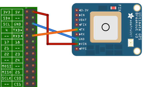
GPS messages require some decoding. Fortunately, there is a good suite of tools to help us do this. Install the following packages:
$ sudo apt-get install gpsd $ sudo apt-get install gpsd-clients
The most important of these is gpsd. This is a tool that reads GPS data from a serial or USB connection as well as other sources and makes it available for client programs to use by providing a local web service on port 2748.
To start the gpsd service running, issue the following command:
$ sudo gpsd /dev/ttyAMA0
You can see if it is working by entering the command:
$ cgps -s
The -s is optional; it just suppresses the display of the raw data (see Figure 12-16).
The third package that we installed (python-gps) is, as you might expect, a Python library for accessing the GPS data in a nice, convenient form. You will use python_gps with a short test program to display just the latitude, longitude, and time.
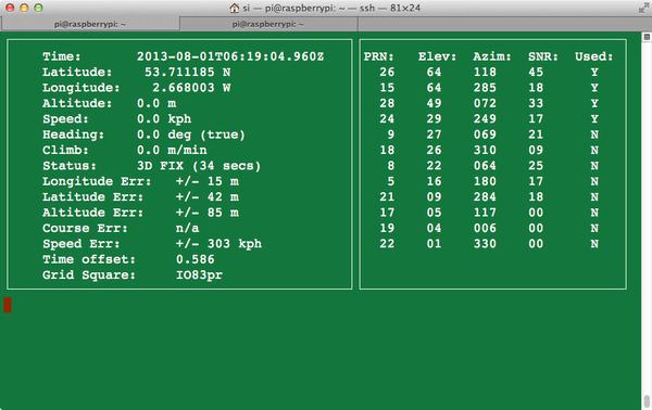
Open an editor (nano or IDLE) and paste in the following code. Do not call the file gps.py, or it will conflict with the Python GPS library. As with all the program examples in this book, you can also download the program from the Code section of the Raspberry Pi Cookbook website, where it is called gps_test.py.
fromgpsimport*session=gps()session.stream(WATCH_ENABLE|WATCH_NEWSTYLE)whileTrue:report=session.next()ifreport.keys()[0]=='epx':lat=float(report['lat'])lon=float(report['lon'])("lat=%f\tlon=%f\ttime=%s"%(lat,lon,report['time']))time.sleep(0.5)
Run the program, and you should see some trace like this:
$ python gps_test.py lat=53.710257 lon=-2.664245 time=2013-08-01T08:06:24.960Z lat=53.710258 lon=-2.664252 time=2013-08-01T08:06:25.960Z lat=53.710258 lon=-2.664252 time=2013-08-01T08:06:25.960Z lat=53.710248 lon=-2.664243 time=2013-08-01T08:06:26.960Z lat=53.710248 lon=-2.664243 time=2013-08-01T08:06:26.960Z lat=53.710248 lon=-2.664250 time=2013-08-01T08:06:27.960Z
The program creates a session and then establishes a stream of data to be read. The GPS will repeatedly spit out messages in different formats. The if command selects just the messages you want; those that contain the positional information. The parts of the message are stored in a dictionary from which the fields can be accessed and displayed.
Besides using the GPS data with Python, you can also use the xgps tool to display the GPS data (Figure 12-17). Just enter the command:
$ xgps
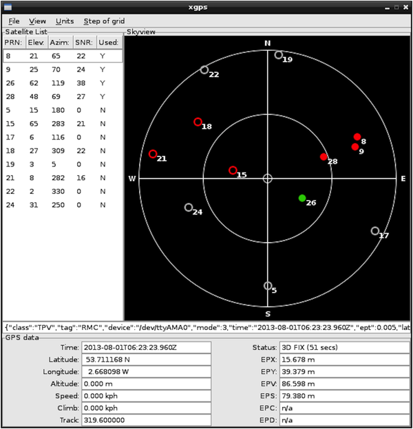
This utility requires a display, so you should run it from the Raspberry Pi itself or by using VNC (Recipe 2.8) or RDP (Recipe 2.9).
There are at least two ways to solve this problem. The most straightforward is to use the sys.stdin.read function. This has the advantage over the other method of not requiring a graphical user interface to be running, so a program using it can be run from an SSH session.
Open an editor (nano or IDLE) and paste in the following code. As with all the program examples in this book, you can also download the program from the Code section of the Raspberry Pi Cookbook website, where it is called keys_sys.py.
importsys,tty,termiosdefread_ch():fd=sys.stdin.fileno()old_settings=termios.tcgetattr(fd)try:tty.setraw(sys.stdin.fileno())ch=sys.stdin.read(1)finally:termios.tcsetattr(fd,termios.TCSADRAIN,old_settings)returnchwhileTrue:ch=read_ch()ifch=='x':break("key is: "+ch)
The alternative to this is to use Pygame. Pygame is a Python library intended for writing games. It can also be used to detect keypresses. You could then use this to perform some action. This recipe must be made using Python 2 rather than Python 3, as Pygame is not included with Python 3.
The following example program illustrates the use of Pygame to print out a message each time a key is pressed. However, it only works if the program has access to the windowing system, so you will need to run it using VNC (Recipe 2.8), RDP (Recipe 2.9), or directly on the Raspberry Pi. The example code is in the file keys_pygame.py on the book’s website.
importpygameimportsysfrompygame.localsimport*pygame.init()screen=pygame.display.set_mode((640,480))pygame.mouse.set_visible(0)whileTrue:foreventinpygame.event.get():ifevent.type==QUIT:sys.exit()ifevent.type==KEYDOWN:("Code: "+str(event.key)+" Char: "+chr(event.key))
This opens a blank Pygame window, and keys will only be intercepted if the Pygame window is selected. The program produces output in the Terminal window from which the program is run.
If you press an arrow key or Shift key with the first stdin read approach, the program will throw an error because those keys don’t have an ASCII value.
$python keys_pygame.py Code: 97 Char: a Code: 98 Char: b Code: 99 Char: c Code: 120 Char: x Code: 13 Char:
In this case, Ctrl-C won’t stop this program from running. To stop the program, click the X on the PyGame window.
When you are using the Pygame approach, other keys have constant values defined for them, which allows you to use the cursor and other non-ASCII keys (like the up arrow key and Home) on the keyboard. This isn’t possible with the other approach.
Intercepting keyboard events can also be an alternative to using a matrix keypad (Recipe 12.8).
The solution to this is very similar to that of using Pygame to intercept keyboard events (Recipe 12.11).
Open an editor (nano or IDLE) and paste in the following code. As with all the program examples in this book, you can also download the program from the Code section of the Raspberry Pi Cookbook website, where it is called mouse_pygame.py.
importpygameimportsysfrompygame.localsimport*pygame.init()screen=pygame.display.set_mode((640,480))pygame.mouse.set_visible(0)whileTrue:foreventinpygame.event.get():ifevent.type==QUIT:sys.exit()ifevent.type==MOUSEMOTION:("Mouse: (%d,%d)"%event.pos)
The MOUSEMOTION event is triggered whenever the mouse moves within the Pygame window. You can find the coordinates from the pos value of the event. The coordinates are absolute coordinates relative to the top-left corner of the window:
Mouse: (262, 285) Mouse: (262, 283) Mouse: (262, 281) Mouse: (262, 280) Mouse: (262, 278) Mouse: (262, 274) Mouse: (262, 270) Mouse: (260, 261) Mouse: (258, 252) Mouse: (256, 241) Mouse: (254, 232)
Other events that you can intercept are MOUSEBUTTONDOWN and MOUSEBUTTONUP. These can be used to detect when the left mouse button has been pressed or released.
The Pygame documentation for mouse can be found at the Pygame website.
Use an real-time clock (RTC) module.
A very common RTC chip is the DS1307. It has an I2C interface and can be bought as a ready-to-use module that includes the chip itself, a quartz crystal for it to maintain accurate timekeeping, and a battery holder for a 3V lithium cell.
To make this recipe, you will need:
A DS1307 or compatible RTC module (see “Modules”)
Female-to-female jumper wires (see “Prototyping Equipment”)
The RTC module that you are using must be 3.3V-compatible. That means that its I2C interface should either have no pull-up resistors at all, or they should pull up to 3.3V and not 5V. When using the Adafruit model here, simply don’t include the two resistors when soldering together the module. If you have a ready-made module, carefully remove any pull-up resistors.
Assemble the RTC module if it is in kit form, remembering to omit pull-up resistors, and then connect the module to the Raspberry Pi, as shown in Figure 12-18.
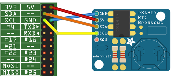
The DS1307 is an I2C module, so your Raspberry Pi must be set up to work with I2C (see Recipe 9.3). You can check that the device is visible using I2C tools (Recipe 9.4).
$ sudo i2cdetect -y 1
0 1 2 3 4 5 6 7 8 9 a b c d e f
00: -- -- -- -- -- -- -- -- -- -- -- -- --
10: -- -- -- -- -- -- -- -- -- -- -- -- -- -- -- --
20: -- -- -- -- -- -- -- -- -- -- -- -- -- -- -- --
30: -- -- -- -- -- -- -- -- -- -- -- -- -- -- -- --
40: -- -- -- -- -- -- -- -- -- -- -- -- -- -- -- --
50: -- -- -- -- -- -- -- -- -- -- -- -- -- -- -- --
60: -- -- -- -- -- -- -- -- 68 -- -- -- -- -- -- --
70: -- -- -- -- -- -- -- --
The 68 in the table indicates that the RTC module is connected to the I2C bus at hex address 68.
If you are using one of the original Raspberry Pi model B, revision 1, boards, then use 0 after the y option in the preceding line. The revision 1 boards were distinctive for having a black audio socket.
You now need to run the following commands so that the RTC can be used with a program called hwclock.
$ sudo modprobe rtc-ds1307 $ sudo bash $ echo ds1307 0x68 > /sys/class/i2c-adapter/i2c-1/new_device
Once again, if you are using a revision 1 board, change i2c-1 to i2c-0.
You can now access the RTC using the following command:
$ sudo hwclock -r Sat 01 Jan 2000 00:08:08 UTC -0.293998 seconds
As you can see, the clock is not currently set.
To set the time on the RTC module, you first need to make sure that your Raspberry Pi has the right time. If your Pi is connected to the Internet, this should happen automatically. You can check this by using the date command:
$ date Tue Aug 20 06:42:47 UTC 2013
If the time is wrong, you can also set it manually using date (Recipe 3.35). To transfer the Raspberry Pi system time onto the RTC module, use the following command:
$ sudo hwclock -w
You can then read the time by using the -r option:
$ sudo hwclock -r Wed 02 Jan 2013 03:11:43 UTC -0.179786 seconds
The RTC having the correct time is pointless unless it is used to set the correct system time in Linux when it reboots. To arrange for this to happen, you need to make a few configuration changes.
First, edit /etc/modules (using sudo nano /etc/modules) and add rtc-ds1307 to the end of the list of modules. If you have already added some modules while setting up I2C, SPI, and other options, your file might look something like this:
# /etc/modules: kernel modules to load at boot time. # # This file contains the names of kernel modules that should be loaded # at boot time, one per line. Lines beginning with "#" are ignored. # Parameters can be specified after the module name. snd-bcm2835 i2c-bcm2708 i2c-dev spidev rtc-ds1307
Next, you need two commands to run automatically during startup to set the system time. So edit the file /etc/rc.local using the command sudo nano /etc/rc.local, and just before the final exit 0 line, insert the following two lines. Remember to change i2c-1 to i2c-0 if you are using a revision 1 Pi.
$ echo ds1307 0x68 > /sys/class/i2c-adapter/i2c-1/new_device $ sudo hwclock -s
When you finish, the file should look something like this:
## In order to enable or disable this script, just change the execution# bits.## By default, this script does nothing.# Print the IP address_IP=$(hostname -I)||trueif["$_IP"];thenprintf"My IP address is %s\n""$_IP"fiechods1307 0x68 > /sys/class/i2c-adapter/i2c-1/new_device sudo hwclock -sexit0
Now, when you reboot, your Raspberry Pi should set its system time from the RTC. However, if there is an Internet connection available, this will take precedence for setting the time.
An RTC is not essential for a Raspberry Pi by any means, since a Raspberry Pi that is connected to the Internet will automatically connect to a network time server and set its own clock. However, you may not always be using the Pi when connected to a network, in which case a hardware RTC is a good option.
AB Electronics has a neat RTC that plugs directly into the GPIO socket. This is shown in Figure 12-19.
This recipe is based on a tutorial from Adafruit.
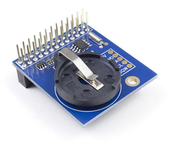
In this chapter, you will look at recipes for using sensors of various types that will allow the Raspberry Pi to measure temperature, light, and more.
Compared to a board like the Arduino, the Raspberry Pi lacks analog inputs. This means that for many sensors, it is necessary to use additional analog-to-digital (ADC) converter hardware. Fortunately, this is relatively easy to do. It is also possible to use resistive sensors with a capacitor and a couple of resistors.
Most of the recipes will require the use of a solderless breadboard and male-to-female jumper wires (see Recipe 9.8).
Be sure to check out the accompanying video for this recipe at http://razzpisampler.oreilly.com.
You can measure resistance on a Raspberry Pi using nothing more than a capacitor, a couple of resistors, and two GPIO pins. In this case, you will be able to estimate the position of the knob on a small variable resistor (trimpot) by measuring its resistance from its slider contact to one end of the pot.
To make this recipe, you will need:
Breadboard and jumper wires (see “Prototyping Equipment”)
10kΩ trimpot (see “Resistors and Capacitors”)
Two 1kΩ resistors (see “Resistors and Capacitors”)
330 nF capacitor (see “Resistors and Capacitors”)
Figure 13-1 shows the arrangement of components on the breadboard.
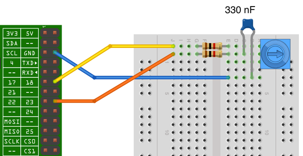
Open an editor (nano or IDLE) and paste in the following code. As with all the program examples in this book, you can also download the program from the Code section of the Raspberry Pi Cookbook website, where it is called pot_step.py.
importRPi.GPIOasGPIOimporttime,mathC=0.36# uFR1=1000# OhmsGPIO.setmode(GPIO.BCM)# Pin a charges the capacitor through a fixed 1k resistor# and the pot in series# Pin b discharges the capacitor through a fixed 1k resistora_pin=18b_pin=23# Discharge the capacitor, leaving it ready to start filling updefdischarge():GPIO.setup(a_pin,GPIO.IN)GPIO.setup(b_pin,GPIO.OUT)GPIO.output(b_pin,False)time.sleep(0.1)# Return the time taken (uS) for the voltage on the capacitor# to count as a digital input HIGH# which is 1.65V or higherdefcharge_time():GPIO.setup(b_pin,GPIO.IN)GPIO.setup(a_pin,GPIO.OUT)GPIO.output(a_pin,True)t1=time.time()whilenotGPIO.input(b_pin):passt2=time.time()return(t2-t1)*1000000# Take an analog reading as the time taken to charge after# first discharging the capacitordefanalog_read():discharge()t=charge_time()discharge()returnt# Convert the time taken to charge the cpacitor into a value of resistance# To reduce errors, do it 100 times and take the averagedefread_resistance():n=10total=0;foriinrange(1,n):total=total+analog_read()t=total/float(n)T=t*0.632*3.3r=(T/C)-R1returnrtry:whileTrue:(read_resistance())time.sleep(0.5)finally:GPIO.cleanup()
When you run the program, you should see some output like this:
$ sudo python pot_step.py 10049.2157936 10105.1559448 10158.6098671 11331.0049375 10162.6154582 10156.8142573 9501.27855937 8216.17444356
The reading will vary as you rotate the knob of the trimpot. Ideally, the reading of resistance would vary between 0 and 10,000Ω but in practice, there will be some error. You might like to tweak the value of the constant C at the top of the program if you want more accurate readings, but remember the value of C will probably have to be changed if you put another capacitor in, even if the capacitor was nominally of the same value.
To explain how this program works, I first need to explain how the step response technique can be used to measure the resistance of the variable resistor.
Figure 13-2 shows the schematic diagram for the recipe.
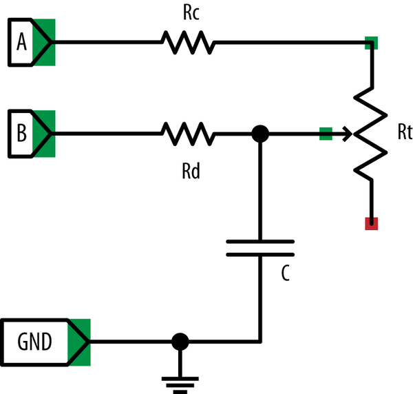
This way of doing things is called step response because it works by seeing how the circuit responds from the step change when an output is switched from low to high.
You can think of a capacitor as a tank of electricity, and as it fills with charge, the voltage across it increases. You can’t measure that voltage directly, because the Raspberry Pi doesn’t have an Analog to Digital Converter (ADC). However, you can time how long it takes for the capacitor to fill with charge to the extent that it gets above the 1.65V or so that constitutes a high digital input. The speed at which the capacitor fills with charge depends on the value of the variable resistor (Rt). The lower the resistance, the faster the capacitor fills with charge and the voltage rises.
To be able to get a good reading, you must also be able to empty the capacitor each time before you take a reading. In Figure 13-2, connection A is used to charge the capacitor through Rc and Rt, and connection B is used to discharge (empty) the capacitor through Rd. The resistors Rc and Rd are used to prevent too much current from flowing as the capacitor is charged and discharged through the Raspberry Pi’s relatively fragile GPIO pins.
The steps involved in taking a reading are first to discharge the capacitor through Rd and then to let it charge through Rc and Rt.
To discharge it, connection A (GPIO 18) is set to be an input, effectively disconnecting Rc and Rt from the circuit. Connection B (GPIO 23) is then set to be an output and low. This is held there for 100 milliseconds to empty the capacitor.
Now that the capacitor is empty, you can start to allow charge to flow into it by setting connection B to be an input (effectively disconnecting it) and then enabling connection A to be a high output at 3.3V. Capacitor C will now begin to charge through Rc and Rt. The while loop will do nothing until the voltage at connection B switches from being low to high at about 1.65V.
At that point, the time taken is returned.
Figure 13-3 shows how a resistor and capacitor in this kind of arrangement charge and discharge as the voltage is toggled between high and low.
You can see that the voltage at the capacitor increases rapidly at first but then trails off as the capacitor becomes full. Fortunately, you are interested in the area of the curve up until the capacitor reaches about 1.65V, which is a fairly straight line, meaning that the time taken for the voltage across the capacitor to rise to this point is roughly proportional to the resistance of Rt and hence the position of the knob.
This approach is not hugely accurate, but it is very low cost and easy to use. The inaccuracy is largely because capacitors of a suitably high value are only accurate to 10%.
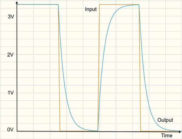
Using a step response works well with all kinds of resistive sensors for light (Recipe 13.2), temperature (Recipe 13.3), and even gas detection (Recipe 13.4).
For more accurate measurements of the trimpot position, see Recipe 13.5, where the pot is used with an ADC converter.
Use the same basic recipe and code as Recipe 13.1, but replace the trimpot with a photoresistor.
To make this recipe, you will need:
Breadboard and jumper wires (see “Prototyping Equipment”)
Photoresistor (see “Resistors and Capacitors”)
Two 1kΩ resistors (see “Resistors and Capacitors”)
330 nF capacitor (see “Resistors and Capacitors”)
All these parts are included in the Electronics Starter Kit for Raspberry Pi from Monk Makes (see “Prototyping Equipment”).
Figure 13-4 shows the arrangement of components on the breadboard.
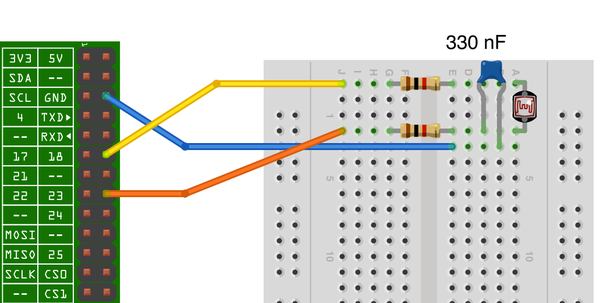
Using the same program as Recipe 13.1 (pot_step.py), you will see the output vary as you move your hand over the photoresistor to cut out some of the light.
This solution provides relatively reliable readings of light levels. As an adaptation of the general solution for using resistive sensors (Recipe 13.1), it also copes with measuring a resistance of 0Ω without any risk of damaging the GPIO pins of the Raspberry Pi. Since a photoresistor is never going to dip to zero resistance, you can take a few shortcuts and do away with both 1kΩ resistors and one of the GPIO pins and make the simpler schematic shown in Figure 13-5.
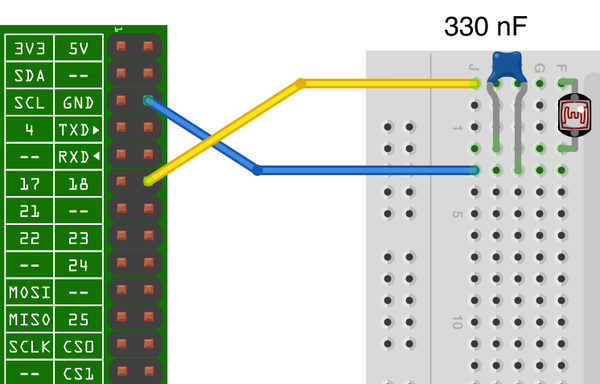
In this variation, the same GPIO pin will be used to charge and discharge the capacitor and check to see if it is above the input HIGH threshold. The program can be found in photoresistor_step.py.
importRPi.GPIOasGPIOimporttimeGPIO.setmode(GPIO.BCM)pin=18defdischarge():GPIO.setup(pin,GPIO.OUT)GPIO.output(pin,False)time.sleep(0.1)# Return the time taken for the capacitor to go HIGH# which is 1.65V or higherdefcharge_time():t1=time.time()GPIO.setup(pin,GPIO.IN)whilenotGPIO.input(pin):# charge for 1msGPIO.setup(pin,GPIO.OUT)GPIO.output(pin,True)time.sleep(0.001)# set to input to test againGPIO.setup(pin,GPIO.IN)time.sleep(0.001)t2=time.time()return(t2-t1)*1000000# Take an analog reading as the time taken to charge Cdefanalog_read():discharge()returncharge_time()whileTrue:(analog_read())time.sleep(0.5)
In only using one pin, after discharging the capacitor through the photoresistor, the charge_time function charges the capacitor through the photoresistor for just 1 ms. It sets the pin to be an input and tests to see if it’s over the HIGH threshold, and then repeats until it is HIGH.
A photoresistor is a resistor whose resistance varies depending on the amount of light coming through its transparent window. The brighter the light, the lower the resistance. Typically, the resistance varies between about 1kΩ in bright light up to perhaps 100kΩ in complete darkness.
The sensors can only really give a rough idea of the light level.
You could also use an ADC with the photoresistor (Recipe 13.5).
A thermistor is a resistor whose resistance varies with temperature. Use the step response method (Recipe 13.1) to measure the resistance of the thermistor and then calculate the temperature.
To make this recipe, you will need:
Breadboard and jumper wires (see “Prototyping Equipment”)
1k Thermistor (see “Resistors and Capacitors”)
Two 1kΩ resistors (see “Resistors and Capacitors”)
330 nF capacitor (see “Resistors and Capacitors”)
All these parts are included in the Electronics Starter Kit for Raspberry Pi from Monk Makes (see “Prototyping Equipment”). When you get your thermistor, make sure that you know its values of Beta and R0 (resistance at 25C) and that it is a Negative Temperature Coefficient (NTC) device.
Figure 13-6 shows the breadboard layout for this recipe.
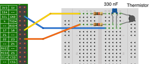
Open an editor (nano or IDLE) and paste in the following code. As with all the program examples in this book, you can also download the program from the Code section of http://www.raspberrypicookbook.com, where it is called thermistor.py.
importRPi.GPIOasGPIOimporttime,mathC=0.36# uFR1=1000# OhmsB=3800.0# The thermistor constantR0=1100.0# The resistance of the thermistor at 25CGPIO.setmode(GPIO.BCM)# Pin a charges the capacitor through a fixed 1k resistor# and the thermistor in series# Pin b discharges the capacitor through a fixed 1k resistora_pin=18b_pin=23# Discharge the capacitor, leaving it ready to start filling updefdischarge():GPIO.setup(a_pin,GPIO.IN)GPIO.setup(b_pin,GPIO.OUT)GPIO.output(b_pin,False)time.sleep(0.1)# Return the time taken (uS) for C to charge# which is 1.65V or higherdefcharge_time():GPIO.setup(b_pin,GPIO.IN)GPIO.setup(a_pin,GPIO.OUT)GPIO.output(a_pin,True)t1=time.time()whilenotGPIO.input(b_pin):passt2=time.time()return(t2-t1)*1000000# Take an analog reading from charge timedefanalog_read():discharge()t=charge_time()discharge()returnt# Convert the time taken to charge the capacitor into a value of resistance# To reduce errors, do it 10 times and take the average.defread_resistance():n=10total=0;foriinrange(1,n):total=total+analog_read()t=total/float(n)T=t*0.632*3.3r=(T/C)-R1returnrdefread_temp_c():R=read_resistance()t0=273.15# 0 deg C in Kt25=t0+25.0# 25 deg C in K# Steinhart-Hart equation - Google itinv_T=1/t25+1/B*math.log(R/R0)T=(1/inv_T-t0)returnTtry:whileTrue:(read_temp_c())time.sleep(0.5)finally:GPIO.cleanup()
When you run the program, you will see a series of temperature measurements in degrees C. To convert to degrees F, use the formula Tf = Tc * 9 / 5 + 32.
$ sudo python thermistor.py 18.3040458984 17.8302664759 17.3917856854 17.9286173793
Most of the code in this project is the same as for Recipe 13.1. The new part is the function read_temp_c, which converts the resistance value into a temperature in degrees C.
Calculating the temperature from the resistance of the thermistor requires some fairly hairy math using logarithms called the Steinhart-Hart equation. This equation needs to know two things about the thermistor: its resistance at 25 degrees C (called T0 or sometimes T25) and a constant for the thermistor called Beta, or sometimes just B. If you use a different thermistor, you will need to plug these values into the variables B and R0 at the top of the program.
Note that a capacitor typically only has an accuracy of 10%, and thermistors are similarly inaccurate in their value of R0, so to get useful readings from the thermistor, you will need to tweak the variables C and R0.
Adjust C first, using a 1kΩ 1% accuracy resistor in place of the pot in Recipe 13.1. Then adjust R0 to give readings that agree with an accurate thermometer.
To measure temperature using a TMP36, see Recipe 13.8.
To measure temperature using a digital temperature sensor (DS18B20), see Recipe 13.11.
To measure temperature using a Sense HAT, see Recipe 13.10.
Low-cost resistive gas sensors are available that can easily be wired to a Raspberry Pi to detect gases such as methane. You can use the step response method that you first used in Recipe 13.1.
To make this recipe, you will need:
Breadboard and jumper wires (see “Prototyping Equipment”)
Methane sensor (see “Modules”)
Two 1kΩ resistors (see “Resistors and Capacitors”)
330 nF capacitor (see “Resistors and Capacitors”)
The sensor contains a heating element that requires 5V at up to 150mA. The Raspberry Pi is capable of providing this as long as its power supply can supply the extra 150mA.
The sensor module has rather thick legs—too thick to fit into breadboard holes. One way around this is to solder short lengths of solid core wire to each lead (Figure 13-7). Another is to buy SparkFun’s gas sensor breakout board.

Wire the breadboard as shown in Figure 13-8 if you’re using the SparkFun breakout board, or as shown in Figure 13-9 if you soldered longer leads to the gas sensor.
Note that the direct connection shown in Figure 13-9 uses the same symbol for the breakout board rather than the sensor on its own, but if you look carefully, the connections are to the six sensor pins, not the four pins of the breakout.
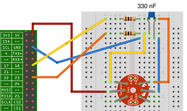
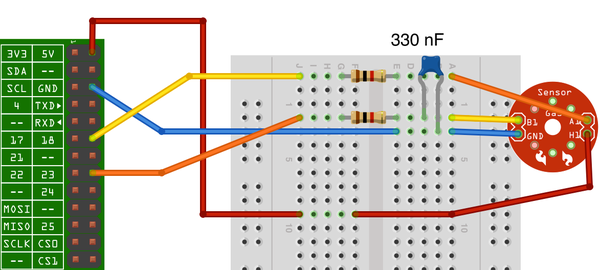
You can use the exact same program as Recipe 13.1, and you can test the methane sensor by breathing on it. You should see the readings from the sensor drop when you breathe on it.
The obvious use of a methane gas sensor is for novelty fart detecting projects. A more serious use would be for detecting leaks of natural gas. You could, for instance, imagine a Raspberry Pi home-watch project that monitored the home with various sensors. It could then send you an email, while you are on vacation, informing you that your house is about to explode. Or maybe not.
These types of sensors (Figure 13-10) use a heating element that warms a resistive surface impregnated with a catalyst sensitive to a particular gas. When the gas is present, the resistance of the catalyst layer changes.

Both the heater and the sensing surface are electrically just resistors. So both can be connected either way around.
This particular gas sensor is most sensitive to methane, but will also detect other gases to a lesser extent. That is why breathing on the sensor alters the reading, as healthy individuals will not normally breathe out methane. The cooling effect of blowing on the element may also have an effect.
The datasheet for this sensor can be found at http://bit.ly/1gYupsu. This will give you all sorts of useful information about the sensor’s sensitivity to various gases.
There are a range of these low-cost sensors available for sensing different gases. For a list of sensors offered by SparkFun, see the SparkFun website.
The Raspberry Pi GPIO connector has only digital inputs. If you wish to measure a voltage, you need to use a separate analog-to-digital converter (ADC).
Use the MCP3008 eight-channel ADC chip. This chip actually has eight analog inputs, so you can connect up to eight sensors to one of these and interface to the chip using the Raspberry Pi SPI interface.
To make this recipe, you will need:
Breadboard and jumper wires (see “Prototyping Equipment”)
MCP3008 eight-channel ADC IC (see “Integrated Circuits”)
10kΩ trimpot (see “Resistors and Capacitors”)
Figure 13-11 shows the breadboard layout for using this chip. Make sure that you get the chip facing the right way. The little notch in the package should be toward the top of the breadboard.
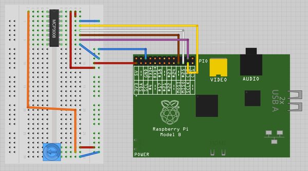
The variable resistor has one end connected to 3.3V and the other to ground, which allows the middle connection to be set to any voltage between 0 and 3.3V.
Before trying the program, make sure you have SPI enabled and the SPI Python library installed (Recipe 9.5).
Open an editor (nano or IDLE) and paste in the following code. As with all the program examples in this book, you can also download the program from the Code section of http://www.raspberrypicookbook.com, where it is called adc_test.py.
importspidev,timespi=spidev.SpiDev()spi.open(0,0)defanalog_read(channel):r=spi.xfer2([1,(8+channel)<<4,0])adc_out=((r[1]&3)<<8)+r[2]returnadc_outwhileTrue:reading=analog_read(0)voltage=reading*3.3/1024("Reading=%d\tVoltage=%f"%(reading,voltage))time.sleep(1)
The interesting part of the program is contained in the analog_read function. This takes a parameter that should be between 0 and 7 and specifies which of the eight analog inputs down the lefthand side of the chip should be read.
The bit manipulation sets up a request for the appropriate channel and then sends the bits to the MCP3008, which reads the resultant data:
$ sudo python adc_test.py Reading=0 Voltage=0.000000 Reading=126 Voltage=0.406055 Reading=221 Voltage=0.712207 Reading=305 Voltage=0.982910 Reading=431 Voltage=1.388965 Reading=527 Voltage=1.698340 Reading=724 Voltage=2.333203 Reading=927 Voltage=2.987402 Reading=1020 Voltage=3.287109 Reading=1022 Voltage=3.293555
The MCP3008 has 10-bit ADCs, so when you take a reading, it gives you a number between 0 and 1023. The test program converts this into a voltage reading by multiplying the reading by the voltage range (3.3V) and then dividing it by 1,024.
You can combine any of the following recipes that use the MCP3008 to allow readings to be taken from up to eight sensors.
You can also use resistive sensors with the MCP3008 by combining them with a fixed-value resistor and arranging them as a voltage divider (see Recipe 13.6 and Recipe 13.7).
If you’re just interested in detecting the turning of a knob, you can use a rotary encoder instead of a pot (Recipe 12.7).
You can also detect the position of a pot without the use of an ADC chip by using the step response method (Recipe 13.1).
Check out the datasheet for the MCP3008.
The Explorer HAT Pro from Pimoroni also has an ADC (Recipe 9.17).
You want to measure a voltage, but it is higher than the 3.3V possible using an MCP3008 (Recipe 13.5).
Use a pair of resistors to act as a voltage divider to reduce the voltage to a suitable range.
To try this recipe, you will need:
Breadboard and jumper wires (see “Prototyping Equipment”)
MCP3008 eight-channel ADC IC (see “Integrated Circuits”)
10kΩ resistor (see “Resistors and Capacitors”)
3.3kΩ resistor (see “Resistors and Capacitors”)
9V battery and clip lead
Figure 13-12 shows the arrangement for this, using a breadboard. The setup will measure the voltage of the battery.
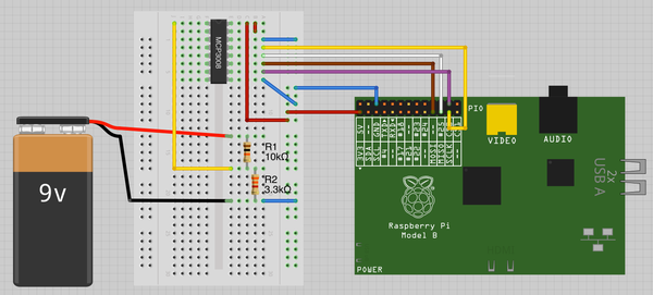
Never use this recipe to measure high-voltage AC, or for that matter, any type of AC. It is for low-voltage DC only.
Open an editor (nano or IDLE) and paste in the following code. As with all the program examples in this book, you can also download the program from the Code section of the Raspberry Pi Cookbook website, where it is called adc_scaled.py.
importspidevR1=10000.0R2=3300.0spi=spidev.SpiDev()spi.open(0,0)defanalog_read(channel):r=spi.xfer2([1,(8+channel)<<4,0])adc_out=((r[1]&3)<<8)+r[2]returnadc_outreading=analog_read(0)voltage_adc=reading*3.3/1024voltage_actual=voltage_adc/(R2/(R1+R2))("Battery Voltage="+str(voltage_actual))
The program is very similar to that of Recipe 13.5. The main difference is the scaling, using the values of the two resistors. The values of these two resistors are held in the variables R1 and R2.
When you run the program, the battery voltage will be displayed:
$ sudo python adc_scaled.py Battery Voltage=8.62421875
Read the discussion carefully before attaching anything higher than 9V, or you may destroy the MCP3008.
This arrangement of resistors is called a voltage divider or sometimes a potential divider (Figure 13-13). The formula for calculating the output voltage, given the input voltage and the values of the two resistors, is:
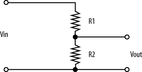
This means that if R1 and R2 were both the same value (say, 1kΩ), then Vout would be half of Vin.
When choosing R1 and R2, you also need to consider the current flowing through R1 and R2. This will be Vin/(R1 + R2). In the preceding example, R1 is 10kΩ and R2 is 3.3kΩ. So the current flowing will be 9V/13.3kΩ = 0.68mA. This is low, but still enough to eventually drain the battery, so do not leave it connected all the time.
To avoid the math, you can use an online resistor calculator.
The voltage divider is also used to convert resistance to voltage when using a resistive sensor with an ADC (Recipe 13.7).
Use a potential divider with one fixed resistor and the resistive sensor to convert the resistance of the sensor into a voltage that can be measured with the ADC.
As an example, you can remake the light sensor project of Recipe 13.2 to use the MCP3008 instead of the step response technique.
To try this recipe, you will need:
Breadboard and jumper wires (see “Prototyping Equipment”)
MCP3008 eight-channel ADC IC (see “Integrated Circuits”)
10kΩ resistor (see “Resistors and Capacitors”)
Photoresistor (see “Resistors and Capacitors”)
Figure 13-14 shows the arrangement for this, using a breadboard.
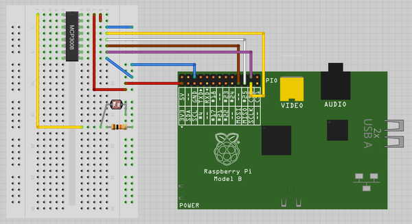
You can use the exact same program as Recipe 13.5 (adc_test.py). Covering up the light sensor with your hand changes the readings. You also need to set up SPI on your Raspberry Pi, so if you haven’t already done so, follow Recipe 9.5.
$ sudo python adc_test.py Reading=341 Voltage=1.098926 Reading=342 Voltage=1.102148 Reading=227 Voltage=0.731543 Reading=81 Voltage=0.261035 Reading=86 Voltage=0.277148
These readings may be quite a bit different, depending on your photoresistor, but the important thing is that the figure changes as the light level changes.
Choice of fixed value resistor is not very critical. If the value is too high or low, then you will find that the range of readings is rather narrow. Select a resistor value somewhere between the minimum and maximum resistance of the sensor. You may need to experiment with a few resistors before deciding on one that suits your sensor over the range of readings you’re interested in. If in doubt, start with 10kΩ and see how that works.
You can swap out the photoresistor for pretty much any resistive sensor. So, for instance, you could use the gas sensor from Recipe 13.4.
To measure light intensity without the complication of an ADC, see Recipe 13.2. For an example of using more than one channel of the ADC at a time, see Recipe 13.12.
Use an MCP3008 ADC chip.
However, unless you need more than one analog channel, you should consider using the DS18B20 digital temperature sensor, which is more accurate and doesn’t require a separate ADC chip (Recipe 13.11).
To try this recipe, you will need:
Breadboard and jumper wires (see “Prototyping Equipment”)
MCP3008 eight-channel ADC IC (see “Integrated Circuits”)
TMP36 temperature sensor (see “Integrated Circuits”)
Figure 13-15 shows the arrangement for this, using a breadboard.
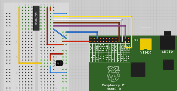
Make sure that you get the TMP36 facing the right way. One side of the package is flat, while the other is curved.
You will need to set up SPI on your Raspberry Pi, so if you haven’t already done so, follow Recipe 9.5.
Open an editor (nano or IDLE) and paste in the following code. As with all the program examples in this book, you can also download the program from the Code section of the Raspberry Pi Cookbook website, where it is called adc_tmp36.py.
importspidev,timespi=spidev.SpiDev()spi.open(0,0)defanalog_read(channel):r=spi.xfer2([1,(8+channel)<<4,0])adc_out=((r[1]&3)<<8)+r[2]returnadc_outwhileTrue:reading=analog_read(0)voltage=reading*3.3/1024temp_c=voltage*100-50temp_f=temp_c*9.0/5.0+32("Temp C=%f\t\tTemp f=%f"%(temp_c,temp_f))time.sleep(1)
The program is based on that of Recipe 13.8. A little bit of additional math calculates the temperature in degrees Celsius and Fahrenheit:
$ sudo python adc_tmp36.py Temp C=19.287109 Temp f=66.716797 Temp C=18.642578 Temp f=65.556641 Temp C=18.964844 Temp f=66.136719 Temp C=20.253906 Temp f=68.457031 Temp C=20.898438 Temp f=69.617188 Temp C=20.576172 Temp f=69.037109 Temp C=21.865234 Temp f=71.357422 Temp C=23.154297 Temp f=73.677734 Temp C=23.476562 Temp f=74.257812 Temp C=23.476562 Temp f=74.257812 Temp C=24.121094 Temp f=75.417969 Temp C=24.443359 Temp f=75.998047 Temp C=25.087891 Temp f=77.158203
The TMP36 outputs a voltage that is proportional to the temperature. According to the datasheet for the TMP36, the temperature in degrees C is calculated as the voltage (in volts) times 100 minus 50.
The TMP36 is fine for measuring the approximate temperature but is specified as having an accuracy of only 2 degrees C. This will only get worse if you attach long leads to it. To some extent, you can calibrate an individual device, but for better accuracy, use a DS18B20 (Recipe 13.11), which has a stated accuracy of 0.5% over a temperature range of -10 to +85 degrees C. Being a digital device, it should not suffer any loss of accuracy when attached to long leads.
Take a look at the TMP36 datasheet.
To measure temperature using a thermistor, see Recipe 13.3.
To measure temperature using a digital temperature sensor (DS18B20), see Recipe 13.11.
To measure temperature using a Sense HAT, see Recipe 13.10.
Use the os library to access the temperature sensor built into the Broadcom chip.
Open an editor (nano or IDLE) and paste in the following code. As with all the program examples in this book, you can also download the program from the Code section of the Raspberry Pi Cookbook website, where it is called cpu_temp.py.
importos,timewhileTrue:dev=os.popen('/opt/vc/bin/vcgencmd measure_temp')cpu_temp=dev.read()(cpu_temp)time.sleep(1)
When you run this program, it will report the temperature. Note that the message printed is actually a string with temp= before the temperature and 'C after it.
$ python cpu_temp.py temp=33.6'C temp=33.6'C
If you want the temperature as a number rather than a string, you need to chop off the extra text and then convert the number to a float. You can find an example program for this in cpu_temp_float.py.
importos,timewhileTrue:dev=os.popen('/opt/vc/bin/vcgencmd measure_temp')cpu_temp_s=dev.read()[5:-3]# top and tail stringcpu_temp=float(cpu_temp_s)(cpu_temp)time.sleep(1)
For more information on chopping up strings, see Recipe 5.15.
To measure temperature using a thermistor, see Recipe 13.3.
To measure temperature using a TMP36, see Recipe 13.8.
To measure temperature using a digital temperature sensor (DS18B20), see Recipe 13.11.
To measure temperature using a Sense HAT, see Recipe 13.10.
Use a Raspberry Pi Sense HAT (Figure 13-16). That way you get all those sensors plus some extras like a display.

Start by following Recipe 9.16 to install the libraries needed by the Sense HAT.
Open an editor (nano or IDLE) and paste in the following code. As with all the program examples in this book, you can also download the program from the Code section of the Raspberry Pi Cookbook website, where it is called sense_hat_thp.py.
fromsense_hatimportSenseHatimporttimehat=SenseHat()whileTrue:t=hat.get_temperature()h=hat.get_humidity()p=hat.get_pressure()('Temp C:{:.2f} Hum:{:.0f} Pres:{:.0f}'.format(t,h,p))time.sleep(1)
When you run the program, the terminal will display something like this:
$ sudo python sense_hat_thp.py Temp C:27.71 Hum:56 Pres:1005 Temp C:27.60 Hum:55 Pres:1005
The temperature is in degrees C, the humidity is the percentage of relative humidity, and the atmospheric pressure is in millibars.
You will find that the temperature readings from the Sense HAT are on the high side. This is because the temperature sensor is built into the humidity sensor and is on the Sense HAT PCB. The Sense HAT generates very little heat (unless you use the display) but the Raspberry Pi under the Sense HAT does get warm and will increase the temperature of the HAT. The best way to avoid this problem is to use a 40-way ribbon cable to move the Sense HAT away from the Raspberry Pi. There are also attempts to adjust the readings by using the temperature reading of the Raspberry Pi, and you can follow a discussion on that at http://bit.ly/1OfEEWf. Personally, I feel that these compensation attempts are probably very specific to the users posting and are unlikely to produce reliable results.
As well as reading the temperature from the humidity sensor, the pressure sensor also has a temperature sensor built in that you can read like this:
t=hat.get_temperature_from_pressure()
It is unclear from the documentation as to whether this reading is any more accurate than using the humidity sensor, but for my setup, it reported temperatures about 1 degree C lower than the humidity sensor.
To get started with the Sense HAT, see Recipe 9.16.
The programming reference for the Sense HAT is here: https://pythonhosted.org/sense-hat/api/.
The Sense HAT also has an accelerometer, gyroscope (Recipe 13.13) and magnetometer (Recipe 13.14) for navigation type projects. It also has a full-color 8×8 LED matrix display (Recipe 14.3).
Use the DS18B20 digital temperature sensor. This device is more accurate than the TMP36 used in Recipe 13.8 and uses a digital interface, so it doesn’t require an ADC chip.
Although the interface to this chip is called one-wire, this just refers to the data pin. You do need at least one other wire to connect to a one-wire device.
To make this recipe, you will need:
Breadboard and jumper wires (see “Prototyping Equipment”)
DS18B20 temperature sensor (see “Integrated Circuits”)
4.7kΩ resistor (see “Resistors and Capacitors”)
Fit the components onto the breadboard as shown in Figure 13-17. Make sure that you get the DS18B20 facing the right way.
The latest version of Raspbian has support for the one-wire interface used by the DS18B20 but you do have to enable it.
To enable 1-wire support, edit the file /boot/config.txt using the command sudo nano /boot/config.txt and add the line shown below to the end of the file. Then reboot your Raspberry Pi for the change to take effect.
$ dtoverlay=w1-gpio
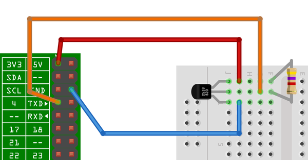
Open an editor (nano or IDLE) and paste in the following code. As with all the program examples in this book, you can also download the program from the Code section of the Raspberry Pi Cookbook website, where it is called temp_DS18B20.py.
importglob,timebase_dir='/sys/bus/w1/devices/'device_folder=glob.glob(base_dir+'28*')[0]device_file=device_folder+'/w1_slave'defread_temp_raw():f=open(device_file,'r')lines=f.readlines()f.close()returnlinesdefread_temp():lines=read_temp_raw()whilelines[0].strip()[-3:]!='YES':time.sleep(0.2)lines=read_temp_raw()equals_pos=lines[1].find('t=')ifequals_pos!=-1:temp_string=lines[1][equals_pos+2:]temp_c=float(temp_string)/1000.0temp_f=temp_c*9.0/5.0+32.0returntemp_c,temp_fwhileTrue:("temp C=%f\ttemp F=%f"%read_temp())time.sleep(1)
When the program is run, it will report the temperature once a second in both degrees Celsius and Fahrenheit:
$ python temp_DS18B20.py temp C=25.187000 temp F=77.336600 temp C=25.125000 temp F=77.225000 temp C=25.062000 temp F=77.111600 temp C=26.312000 temp F=79.361600 temp C=27.875000 temp F=82.175000 temp C=28.875000 temp F=83.975000
At first sight, the program looks a little odd. The interface to the DS18B20 uses a file-like interface. The file interface for the device will always be in the folder /sys/bus/w1/devices/ and the name of the file path will start with 28, but the rest of the file path will be different for each sensor.
The code assumes that there will only be one sensor, and finds the first folder starting with 28. To use multiple sensors, use different index values inside the square brackets.
Within that folder will be a file called w1_slave, which is opened and read to find the temperature.
The sensor actually returns strings of text like this:
81 01 4b 46 7f ff 0f 10 71 : crc=71 YES 81 01 4b 46 7f ff 0f 10 71 t=24062
The remainder of the code extracts the temperature part of this message. This appears after t= and is the temperature in one-thousandths of a degree Celsius.
The read_temp function calculates the temperature in both degrees Celsius and Fahrenheit and returns both values.
Besides the basic chip version of the DS18B20, you can also buy a version encapsulated in a rugged and waterproof probe.
To find out about logging readings, see Recipe 13.20.
This recipe is heavily based on an Adafruit tutorial.
Take a look at the datasheet for the DS18B20.
To measure temperature using a thermistor, see Recipe 13.3.
To measure temperature using a TMP36, see Recipe 13.8.
To measure temperature using a Sense HAT, see Recipe 13.10.
Use an analog accelerometer with an MCP3008 ADC chip to measure the X, Y, and Z analog outputs.
To try this recipe, you will need:
Breadboard and jumper wires (see “Prototyping Equipment”)
MCP3008 eight-channel ADC IC (see “Integrated Circuits”)
ADXL335 triple-axis accelerometer (see “Modules”)
Figure 13-18 shows the arrangement for this, using a breadboard. It uses three channels of the ADC to measure the X, Y, and Z acceleration forces.
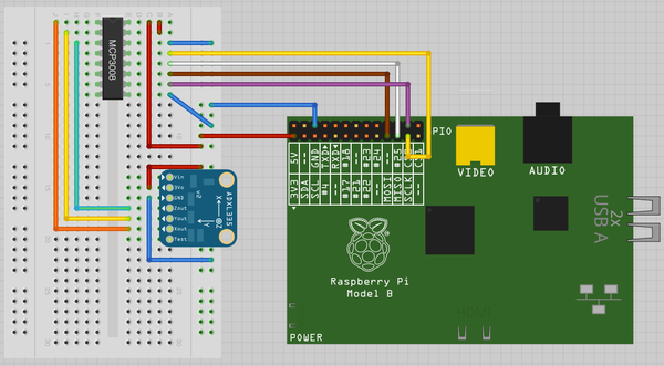
You will need to set up SPI on your Raspberry Pi, so if you have not already done so, follow Recipe 9.5.
Open an editor (nano or IDLE) and paste in the following code. As with all the program examples in this book, you can also download the program from the Code section of the Raspberry Pi Cookbook website, where it is called adc_accelerometer.py.
importspidev,timespi=spidev.SpiDev()spi.open(0,0)defanalog_read(channel):r=spi.xfer2([1,(8+channel)<<4,0])adc_out=((r[1]&3)<<8)+r[2]returnadc_outwhileTrue:x=analog_read(0)y=analog_read(1)z=analog_read(2)("X=%d\tY=%d\tZ=%d"%(x,y,z))time.sleep(1)
The program simply reads the three forces and prints them out:
$ sudo python adc_accelerometer.py X=508 Y=503 Z=626 X=508 Y=504 Z=624 X=506 Y=505 Z=627 X=423 Y=517 Z=579 X=411 Y=513 Z=548 X=532 Y=510 Z=623 X=609 Y=518 Z=495 X=607 Y=521 Z=496 X=610 Y=513 Z=499
The first three readings took place with the accelerometer level. In the next three, the whole breadboard was tipped to one side. You can see that the X reading has decreased. Tipping the breadboard the other way causes the X reading to increase.
The most common use for an accelerometer is to detect tilt. This works because the Z axis force is dominated by the pull of gravity (Figure 13-19).
When the accelerometer is tilted in one direction, some of that vertical force of gravity becomes active on another axis of the accelerometer.

We can use this principle to detect when the tilt is past a certain threshold. The following program (tilt.py) illustrates this point:
importspidev,timespi=spidev.SpiDev()spi.open(0,0)defanalog_read(channel):r=spi.xfer2([1,(8+channel)<<4,0])adc_out=((r[1]&3)<<8)+r[2]returnadc_outwhileTrue:x=analog_read(0)y=analog_read(1)z=analog_read(2)ifx<450:("Left")elifx>550:("Right")elify<450:("Back")elify>550:("Forward")time.sleep(0.2)
When you run the program, you will start to see direction messages. You could use this to control a roving robot or a motorized pan-tilt head with a webcam attached:
$ sudo python tilt.py Left Left Right Forward Forward Back Back
See the datasheet for the accelerometer chip used in the module.
There are many other analog accelerometer modules available. You may find that they give different readings. Make sure that the analog outputs do not exceed 3.3V.
The Sense HAT includes an accelerometer (Recipe 13.13).
You want more accurate orientation information from your Raspberry Pi than the accelerometer from Recipe 13.12 provides.
Use the Inertial Management Unit (IMU) of the Sense HAT. This unit includes a 3-axis accelerometer like the one in Recipe 13.12 but also has a 3-axis gyroscope and magnetometer. The readings from these different sensors are combined to let you get a more accurate orientation for the Sense HAT expressed as pitch, roll, and yaw (as shown in Figure 13-20).

Pitch, roll, and yaw are three terms that come from aviation. They are relative to the axis of the plane’s flight. The pitch is the angle to the horizontal. The roll is the degree of rotation around the plane’s axis of flight (imagine one wing going up and the other down), and yaw is the rotation on the horizontal axis (think changing bearing).
Open an editor (nano or IDLE) and paste in the following code. As with all the program examples in this book, you can also download the program from the Code section of the Raspberry Pi Cookbook website, where it is called sense_hat_orientation.py.
fromsense_hatimportSenseHatsense=SenseHat()sense.set_imu_config(True,True,True)whileTrue:o=sense.get_orientation()("p: {:.0f}, r: {:.0f}, y: {:.0f}".format(o['pitch'],o['roll'],o['yaw']))
The function set_imu_config specifies which of the compass, gyroscope, and accelerometer (in that order) should be used to measure the orientation. Setting all three to True will mean that all are used to make the measurement.
When you run the program, you will see output similar to this:
$ sudo python sense_hat_orientation.py p: 1, r: 317, y: 168 p: 1, r: 318, y: 169
Try tilting the Sense HAT and Raspberry Pi forward toward the USB ports, and you should see the value of pitch increase.
An accelerometer measures forces on a stationary mass and can therefore measure the degree of tilt by calculating how much of the force supplied by gravity (z-axis) influences the force measured on the x and y axes.
A gyroscope is different. It measures the force on moving masses (vibrating back and forth) as those masses turn relative to the path of the movement, using an effect called the Coriolis effect.
For more information on the Sense HAT’s IMU, see https://www.raspberrypi.org/learning/astro-pi-guide/sensors/movement.md.
To measure temperature, humidity, and atmospheric pressure, see Recipe 13.10.
The IMU of the Sense HAT can also be used to make a compass and detect the presence of a magnet (Recipe 13.16).
To find out more about gyroscopes and the Coriolis effect, see https://en.wikipedia.org/wiki/Coriolis_effect.
Use the Python library for the built-in 3-axis magnetometer in the Sense HAT.
First follow Recipe 9.16 to install the Sense HAT library.
Open an editor (nano or IDLE) and paste in the following code. As with all the program examples in this book, you can also download the program from the Code section of the Raspberry Pi Cookbook website, where it is called sense_hat_compass.py.
fromsense_hatimportSenseHatsense=SenseHat()whileTrue:bearing=sense.get_compass()('Bearing: {:.0f} to North'.format(bearing))
When you run this program, you will see a series of bearing readings.
$ sudo python sense_hat_compass.py Bearing: 138 to North Bearing: 138 to North
The compass will be sensitive to any other nearby sources of magnetic field so you may find it difficult to get accurate bearings.
You can find documentation for Sense HAT at https://github.com/RPi-Distro/python-sense-hat and http://pythonhosted.org/sense-hat/api/.
To use the Sense HAT to detect a magnet, see Recipe 13.16.
Use a reed switch (Figure 13-21). It works just like a regular switch except it only activates when a magnet is near. Figure 13-22 shows how a reed switch works.
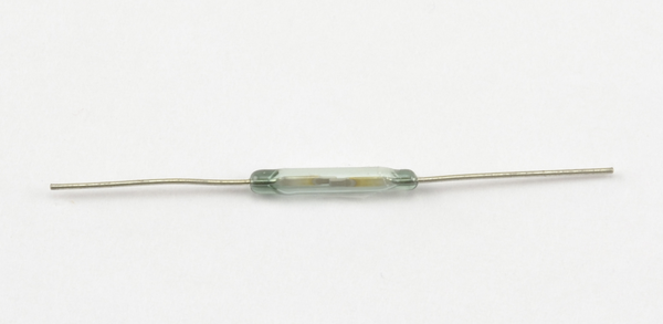
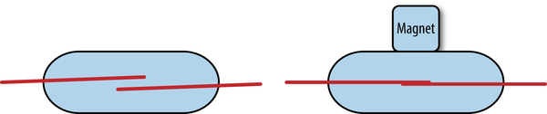
The two reed contacts are encased in a a glass tube. When a magnet is placed near the reed switch, the reeds are pulled together and make contact.
You can use any of the regular switch recipes in Chapter 12 with a reed switch, starting with Recipe 12.1.
Reed switches are a low-tech way of detecting a magnet. They have been around since the 1930s and are extremely reliable. They are also commonly used in security systems where a plastic encased reed switch is placed on a door frame, with a fixed magnet in another plastic enclosure on the door itself. When the door opens, the reed switch contacts open, triggering the alarm.
To detect a magnet using the magnetometer of the Sense HAT, see Recipe 13.16.
Use the Sense HAT’s Python library to interface with its magnetometer.
Open an editor (nano or IDLE) and paste in the following code. As with all the program examples in this book, you can also download the program from the Code section of the Raspberry Pi Cookbook website, where it is called sense_hat_magnet.py.
fromsense_hatimportSenseHatimporttimehat=SenseHat()fill=(255,0,0)whileTrue:reading=int(hat.get_compass_raw()['z'])ifreading>200:hat.clear(fill)time.sleep(0.2)else:hat.clear()
When the magnet gets close to the Sense HAT, the LEDs will all turn red for 1/5 of a second.
It doesn’t matter which axis of the compass data you use; they will all be greatly disrupted by the presence of a fixed magnet.
To detect a magnet using a reed switch, see Recipe 13.15.
For other ways to use the Sense HAT display, see Recipe 14.3.
Use a low-cost SR-04 rangefinder. These devices need two GPIO pins: one to trigger the pulse of ultrasound and the other to monitor how long it takes for the echo to return.
To make this recipe, you will need:
Breadboard and jumper wires (see “Prototyping Equipment”)
SR-04 rangefinder (eBay)
470Ω resistor (see “Resistors and Capacitors”)
270Ω resistor (see “Resistors and Capacitors”)
Fit the components onto the breadboard as shown in Figure 13-23. The resistors are necessary to reduce the echo output of the rangefinder from 5V to 3.3V (see Recipe 9.12).
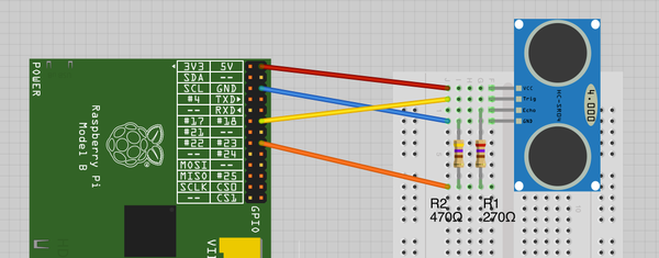
Open an editor (nano or IDLE) and paste in the following code. As with all the program examples in this book, you can also download the program from the Code section of the Raspberry Pi Cookbook website, where it is called ranger.py.
importRPi.GPIOasGPIOimporttimetrigger_pin=18echo_pin=23GPIO.setmode(GPIO.BCM)GPIO.setup(trigger_pin,GPIO.OUT)GPIO.setup(echo_pin,GPIO.IN)defsend_trigger_pulse():GPIO.output(trigger_pin,True)time.sleep(0.0001)GPIO.output(trigger_pin,False)defwait_for_echo(value,timeout):count=timeoutwhileGPIO.input(echo_pin)!=valueandcount>0:count=count-1defget_distance():send_trigger_pulse()wait_for_echo(True,10000)start=time.time()wait_for_echo(False,10000)finish=time.time()pulse_len=finish-startdistance_cm=pulse_len/0.000058distance_in=distance_cm/2.5return(distance_cm,distance_in)whileTrue:("cm=%f\tinches=%f"%get_distance())time.sleep(1)
The operation of the program is described in the next Discussion. When the program is run, it will report the distance in both centimeters and inches, once per second. Use your hand or some other obstacle to change the reading.
sudo python ranger.py cm=154.741879 inches=61.896752 cm=155.670889 inches=62.268356 cm=154.865199 inches=61.946080 cm=12.948595 inches=5.179438 cm=14.087249 inches=5.634900 cm=13.741954 inches=5.496781 cm=20.775302 inches=8.310121 cm=20.224473 inches=8.089789
While there are a number of ultrasonic rangefinders available, the type used here is easy to use and low cost. It works by sending a pulse of ultrasound and then measuring the amount of time taken for the echo to be received. One of the round ultrasonic transducers on the front of the device is the transmitter, and the other is the receiver.
This process is controlled from the Raspberry Pi. The difference between this type of device and more expensive models is that the more expensive versions include their own microcontroller, which carries out all the necessary timing and provides an I2C or serial interface to return a final reading.
When you are using one of these sensors with a Raspberry Pi, the trig (trigger) input to the rangefinder is connected to a GPIO output, and the echo output of the rangefinder is connected to a GPIO input on the Raspberry Pi after having its voltage range lowered from 5V to a safe 3.3V.
Figure 13-24 shows an oscilloscope trace of the sensor in action. The top (red) trace is connected to trig, and the bottom (yellow) trace is connected to echo. You can see that first the trig pin is taken high for a short pulse. There is then a short delay before the echo pin goes high. This stays high for a period that is proportional to the distance from the sensor.
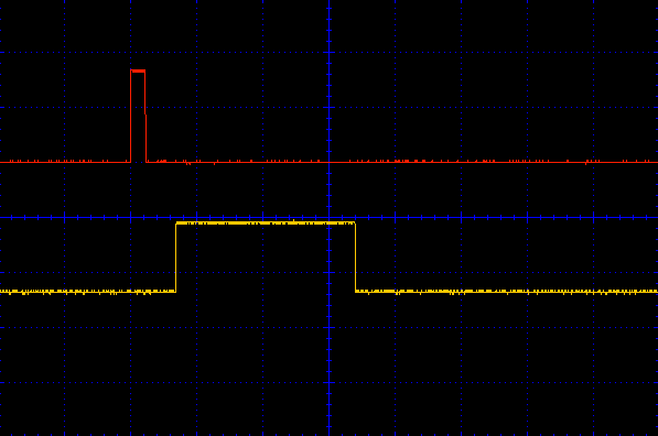
The code for this sensor first generates a trigger pulse (using the function send_trigger_pulse). It must wait until the echo pin goes high, and then times how long the echo pin stays high.
We can then calculate the distance by using the time taken for the echo pulse and the speed of sound.
The wait_for_echo function waits until the echo pin either goes high or low, depending on its first argument. Its second argument is used to provide a timeout so that if for any reason, the echo pin does not change to the state being waited for, the loop won’t hang indefinitely.
This method of measuring distance is not terribly accurate because temperature, pressure, and relative humidity all alter the speed of sound and hence the distance readings.
Take a look at the datasheet for the ultrasonic rangefinder.
Use an Adafruit Capacitative Touch HAT (Figure 13-25).
Touch sensors are a lot of fun and are great for educational use. You can attach anything that conducts electricity a little, including fruit. A popular project is to construct a fruit keyboard using a variety of fruits and vegetables attached to the sense terminals on the board using alligator clips. Then as you touch the different items of fruit, different sounds are made.
The Adafruit Touch HAT uses the Raspberry Pi’s I2C interface. You also need SPI tools installed, so if you have not already done so, follow Recipe 9.3.
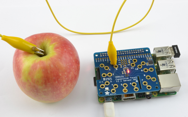
To install the Python library for the HAT, run the following commands:
$ cd /home/pi $ git clone https://github.com/adafruit/Adafruit_Python_MPR121.git $ cd Adafruit_Python_MPR121/ $ sudo python setup.py install
To test out the Touch HAT, run the simpletest.py example supplied with the library by using the commands:
$ cd examples $ sudo python simpletest.py Adafruit MPR121 Capacitive Touch Sensor Test Press Ctrl-C to quit. 0 touched! 0 released!
You can either just touch the connection pads or connect the pads to a piece of fruit using an alligator clip as shown in Figure 13-25.
You will find other example programs in the examples folder, including the ever popular fruit-based musical keyboard.
The Adafruit Touch HAT has 12 touch contacts. If you only need a few touch contacts, you can use the Pimoroni Explorer HAT Pro, which has four alligator-clip–compatible contacts (Figure 13-26).
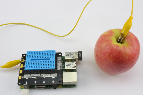
To use the Explorer HAT Pro’s touch contacts, first follow Recipe 9.17 to install the library for the HAT.
In addition to the four terminals on the side, designed for alligator clips, there are also four touch switches labeled 1 to 4 that also use the touch interface.
To try out touch on the Explorer HAT Pro, open a Python console and run the following commands to detect touches:
>>> import explorerhat Explorer HAT Pro detected... >>> explorerhat.touch.five.is_pressed() True >>> explorerhat.touch.five.is_pressed() False >>>
If you run the is_pressed() function while holding the apple, the result will be True; otherwise, it will be False.
For documentation of the Adafruit Touch HAT, see https://www.adafruit.com/products/2340, and for the Explorer HAT Pro, see https://github.com/pimoroni/explorer-hat.
Use the Tkinter library to open a window and write the reading on it as a label with a large font (Figure 13-27).

This example uses data from the ultrasonic rangefinder of Recipe 13.17. So, complete that recipe first if you want to try out this example.
To test out the rangefinder, open an editor (nano or idle) and paste in the following code. As with all the program examples in this book, you can also download the program from the Code section of the book’s website, where it is called gui_sensor_reading.py. The code for measuring distances using the ultrasonic sensor is the same as in Recipe 13.17, so only the section of the code concerned with displaying the value is repeated here:
classApp:def__init__(self,master):self.master=masterframe=Frame(master)frame.pack()label=Label(frame,text='Distance (inches)',font=("Helvetica",32))label.grid(row=0)self.reading_label=Label(frame,text='12.34',font=("Helvetica",110))self.reading_label.grid(row=1)self.update_reading()defupdate_reading(self):cm,inch=get_distance()reading_str="{:.2f}".format(inch)self.reading_label.configure(text=reading_str)self.master.after(500,self.update_reading)root=Tk()root.wm_title('Range Finder')app=App(root)root.geometry("400x300+0+0")root.mainloop()
Athough this recipe uses a distance sensor, it works equally well with the other sensor recipes in this chapter. You just need to change the labels and the method of obtaining a reading from the sensor.
For information on formatting numbers to a certain number of decimal places, see Recipe 7.1.
For an example of displaying sensor data in a web browser rather than an application window, see Recipe 15.2.
Write a Python program that writes the data to a file on a USB flash drive. By writing the file in comma-separated values (CSV), you can import it directly into a spreadsheet, including Gnumeric on the Raspberry Pi (Recipe 4.2).
The example program will log temperature readings recorded from a DS18B20. So if you wish to try this out, first build Recipe 13.11.
Open an editor (nano or IDLE) and paste in the following code. As with all the program examples in this book, you can also download the program from the Code section of the Raspberry Pi Cookbook website, where it is called temp_log.py.
importos,glob,time,datetimelog_period=600# secondslogging_folder=glob.glob('/media/*')[0]dt=datetime.datetime.now()file_name="temp_log_{:%Y_%m_%d}.csv".format(dt)logging_file=logging_folder+'/'+file_nameos.system('modprobe w1-gpio')os.system('modprobe w1-therm')base_dir='/sys/bus/w1/devices/'device_folder=glob.glob(base_dir+'28*')[0]device_file=device_folder+'/w1_slave'defread_temp_raw():f=open(device_file,'r')lines=f.readlines()f.close()returnlinesdefread_temp():lines=read_temp_raw()whilelines[0].strip()[-3:]!='YES':time.sleep(0.2)lines=read_temp_raw()equals_pos=lines[1].find('t=')ifequals_pos!=-1:temp_string=lines[1][equals_pos+2:]temp_c=float(temp_string)/1000.0temp_f=temp_c*9.0/5.0+32.0returntemp_c,temp_fdeflog_temp():temp_c,temp_f=read_temp()dt=datetime.datetime.now()f=open(logging_file,'a')f.write('\n"{:%H:%M:%S}",'.format(dt))f.write(str(temp_c))f.close()("Logging to: "+logging_file)whileTrue:log_temp()time.sleep(log_period)
The program is set to log the temperature every 10 minutes (600 seconds). You can alter this by changing the value of log_period.
When you plug a USB flash drive into a Raspberry Pi, it automatically installs it under /media. If there is more than one removeable drive attached to your Raspberry Pi, then the program uses the first folder it finds inside /media. The name of the logging file is constructed from the current date.
If you open the file in a spreadsheet like Open Office, you will be able to edit it directly. Your spreadsheet may ask you to specify the separator for the data, which will be a comma.
Figure 13-28 shows a set of data captured using this recipe, and the resulting file has been opened with the Gnumeric spreadsheet running on the Raspberry Pi.
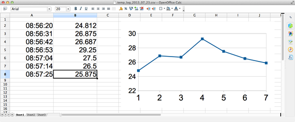
This program could easily be adapted for use with any of the other sensors used in this chapter.
For an example of logging sensor data to a web service, see Recipe 15.6.
Although the Raspberry Pi can use a monitor or TV as a display, it is often nice to use a smaller, more specialized display with it. In this chapter, you will explore a range of different displays that can be attached to a Raspberry Pi.
Some of the recipes require the use of a solderless breadboard and male-to-female jumper wires (see Recipe 9.8).
Be sure to check out the accompanying video for this recipe at http://razzpisampler.oreilly.com.
Use an I2C LED module, such as the model shown in Figure 14-1, to a Raspberry Pi using female-to-female jumper wires.
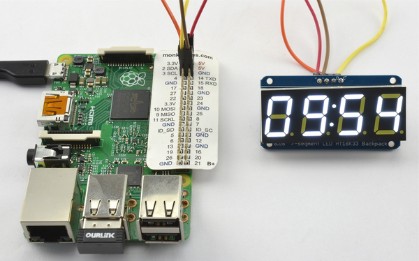
To make this recipe, you need:
Four female-to-female jumper wires (see “Prototyping Equipment”)
Adafruit 4×7-segment LED with I2C backpack (see “Modules”)
The connections between the Raspberry Pi and the module are as follows:
Note that Adafruit also supplies a jumbo-sized LED display. This can be connected to the Raspberry Pi using the connections above, but the larger display has two positive power pins: one for the logic (V_IO) and one for the display (5V). You can just use an extra female-to-female jumper wire to connect this extra pin to the second 5V pin on the GPIO connector. This is because, being a large display, it requires more current for the LED display. Fortunately, the Raspberry Pi can supply enough power for it.
For this recipe to work, you will also need to set up your Raspberry Pi for I2C, so follow Recipe 9.3 first.
The display has an accompanying Python library written by Adafruit. It isn’t installed as a proper library, so to use it, you first need to download the folder structure.
$ git clone https://github.com/adafruit/Adafruit-Raspberry-Pi-Python-Code.git
Change directory into the Adafruit code by using:
$ cd Adafruit-Raspberry-Pi-Python-Code $ cd Adafruit_LEDBackpack
In this folder, you will find a test program that will display the time. Run it by using the command:
$ sudo python ex_7segment_clock.py
If you open the example file ex_7segment_clock.py in nano, you’ll see that the key commands are:
fromAdafruit_7SegmentimportSevenSegment
This imports the library code into your program. You then need to create a instance of SevenSegment using the next line of code. The address supplied as an argument is the I2C address (see Recipe 9.4).
Every I2C slave device has an address number. The LED board has three pairs of solder pads on the back that can be bridged with solder if you want to change the address. This is essential if you need to operate more than one I2C device from a single Raspberry Pi.
segment=SevenSegment(address=0x70)
To actually set the contents of a particular digit, use a line like this one:
segment.writeDigit(0,int(hour/10))
The first argument (0) is the digit position. Note that these positions are 0, 1, 3, and 4. Position 2 is reserved for the two dots in the center of the display.
The second argument is the number to display.
You can find out more about the Adafruit library at http://bit.ly/HQBE6W.
Use an I2C LED module, such as the model shown in Figure 14-2, attached to a Raspberry Pi using female-to-female jumper wires.
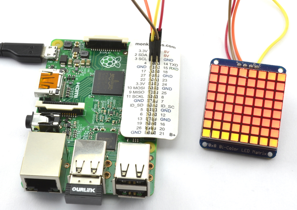
To make this recipe, you need:
Four female-to-female jumper wires (see “Prototyping Equipment”)
Adafruit bicolor LED square-pixel matrix with I2C backpack (see “Modules”)
The connections between the Raspberry Pi and the module are as follows:
For this recipe to work, you will also need to set up your Raspberry Pi for I2C, so follow Recipe 9.3 first.
The display has an accompanying Python library written by Adafruit. It’s not installed as a proper library, so to use it, you first need to download the folder structure.
$ git clone https://github.com/adafruit/Adafruit-Raspberry-Pi-Python-Code.git
Change directory into the Adafruit code by using:
$ cd Adafruit-Raspberry-Pi-Python-Code $ cd Adafruit_LEDBackpack
In this folder, you will find a test program that displays the time as scrolling digits. Run it by using the command:
$ sudo python ex_8x8_color_pixels.py
The program cycles through all the colors for each pixel in turn. The code is listed here, with some of the comments and an unnecessary import removed:
importtimefromAdafruit_8x8importColorEightByEightgrid=ColorEightByEight(address=0x70)iter=0# Continually update the 8x8 display one pixel at a timewhile(True):iter+=1forxinrange(0,8):foryinrange(0,8):grid.setPixel(x,y,iter%4)time.sleep(0.02)
The address supplied as an argument to the next line is the I2C address (see Recipe 9.4):
grid=ColorEightByEight(address=0x70)
Every I2C slave device has an address number. The LED board has three pairs of solder pads on the back that can be bridged with solder if you want to change the address. This is essential if you need to operate more than one I2C device with the same base address from a single Raspberry Pi.
The variable iter gets 1 added to it each time through the loop. The command grid.setPixel takes x and y coordinates as its first two parameters. The final parameter is the color to which the pixel will be set. This is a number between 0 and 3 (0 is off, 1 is green, 2 is red, and 3 is orange).
The variable iter is used to generate the number between 0 and 3 using the % operator, which is the modulo remainder (i.e., what is left over when you divide iter by 4).
You can find out more about this product at http://www.adafruit.com/products/902.
Follow Recipe 9.16 and install the software that the Sense HAT needs and then use the library commands to display text.
The program sense_hat_clock.py illustrates this by repeatedly displaying the date and time in a scrolling message. As with all the program examples in this book, you can also download the program from the Code section of the Raspberry Pi Cookbook website.
fromsense_hatimportSenseHatfromdatetimeimportdatetimeimporttimehat=SenseHat()time_color=(0,255,0)date_color=(255,0,0)whileTrue:now=datetime.now()date_message='{:%d%B %Y}'.format(now)time_message='{:%H:%M:%S}'.format(now)hat.show_message(date_message,text_colour=date_color)hat.show_message(time_message,text_colour=time_color)
Two colors are defined so that the date and time parts of the message can be displayed in different colors. These colors are then used as an optional parameter to show_message.
Other optional parameters to show_message are:
scroll_speed which is actually the delay between each scrolling step rather than the speed. So a higher value makes the scrolling slower. back_colour sets the background color. Note the British spelling of “back_colour” with a “u.”The display can be used for a lot more than just displaying scrolling text. Starting at its most basic, you can set individual pixels using set_pixel, set the orientation of the display using set_rotation, and display an image (albeit a small one) with load_image. The example below, which you can find in sense_hat_taster.py, illustrates these function calls. As with all the program examples in this book, you can also download the program from the Code section of the Raspberry Pi Cookbook website.
The image must be just 8×8 pixels, but most common graphics formats like .jpg and .png can be used and the bit depth will be handled automatically.
fromsense_hatimportSenseHatimporttimehat=SenseHat()red=(255,0,0)hat.load_image('small_image.png')time.sleep(1)hat.set_rotation(90)time.sleep(1)hat.set_rotation(180)time.sleep(1)hat.set_rotation(270)time.sleep(1)hat.clear()hat.set_rotation(0)forxyinrange(0,8):hat.set_pixel(xy,xy,red)hat.set_pixel(xy,7-xy,red)
Figure 14-3 shows the Sense HAT displaying a crude image.
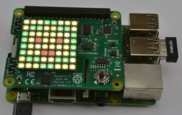
For full documentation on the Sense HAT, see https://pythonhosted.org/sense-hat/api/.
For information on formatting dates and times, see Recipe 7.2.
Other recipes that use the Sense HAT are Recipes 9.16, 13.10, 13.13, 13.14, and 13.16.
Use a Displayotron Pimoroni HAT attached to your Raspberry Pi as shown in Figure 14-4.
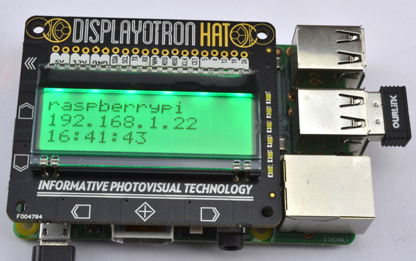
This HAT requires both I2C and SPI to be enabled, so if you have not already done so, follow Recipe 9.3 and Recipe 9.5.
Then fetch the code for its accompanying library from GitHub and install it by using the following commands:
$ git clone https://github.com/pimoroni/dot3k.git $ cd dot3k/python/library $ sudo python setup.py install
By way of example, the following program (displayotron_ip.py) finds the hostname and IP address of your Raspberry Pi and displays them along with the time. If all is well, then the backlit LED will be green, but if the network connection is down, the backlight will turn red.
As with all the program examples in this book, you can also download the program from the Code section of the Raspberry Pi Cookbook website.
importdothat.lcdaslcdimportdothat.backlightasbacklightimporttimefromdatetimeimportdatetimeimportsubprocesswhileTrue:lcd.clear()backlight.rgb(0,255,0)try:hostname=subprocess.check_output(['hostname']).split()[0]ip=subprocess.check_output(['hostname','-I']).split()[0]t='{:%H:%M:%S}'.format(datetime.now())lcd.write(hostname)lcd.set_cursor_position(0,1)lcd.write(ip)lcd.set_cursor_position(0,2)lcd.write(t)except:backlight.rgb(255,0,0)time.sleep(1)
The test program imports the necessary libraries, including subprocess (see Recipe 7.15), which will be used to find the IP address (see Recipe 2.2) of the Raspberry Pi and its hostname.
The main methods in the library are:
lcd.clear clears the display of any textlcd.set_cursor_position sets the position for new text to be written to the column and row specified as its two parameterslcd.write adds the text supplied as its parameter to the current cursor positionbacklight.rgb sets the red, green, and blue values of the backlight (0 to 255)You can find out more about this HAT on PiMoroni’s product page.
To attach a low-cost LCD module directly to a Raspberry Pi without a HAT, see Recipe 14.5.
Use an HD44780-compatible LCD module and wire it to the GPIO connector.
This is clearly a lot more complex than using a ready-made shield, but, if you are planning a complex project where the display is one element and you need access to other GPIO pins, then it is useful to know how to use an LCD module directly.
You will find many low-cost LCD modules, such as the one shown connected to a Raspberry Pi in Figure 14-5. These have 16 pins, although fortunately, not all of them have to be connected to a GPIO pin.
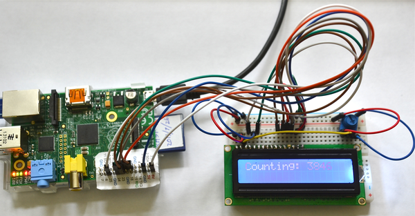
These modules are available in a number of sizes and are specified by the number of columns and rows of letters they can display. So, for example, the module used in this recipe is described as 16×2 because it can display two rows each of 16 characters. Other common sizes are 8×1, 16×1, 16×2, 20×2, and 20×4.
To make this recipe, you will need:
Breadboard and jumper wires (see “Prototyping Equipment”)
16×2 HD44780-compatible LCD module (see “Modules”)
Row of 16 header pins (see “Miscellaneous”)
10kΩ trimpot (see “Resistors and Capacitors”)
Figure 14-6 shows the breadboard layout for connecting the display. The LCD modules are not normally supplied with header pins, so you will need to solder these in place.
The trimpot is used to control the contrast of the display. Note that if it looks like the project has not worked, try moving the knob of the trimpot over its entire range. It may well be that the contrast is so off that the display characters are not visible at all.
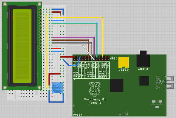
The Adafruit Raspberry Pi example code, available from GitHub, includes a library for controlling LCD displays that use the HD44780 driver. Before installing it, follow Recipe 9.2 to install the RPi.GPIO library.
The Adafruit library is not installed as a proper library, so to use it, you first need to download the folder structure.
$ git clone https://github.com/adafruit/Adafruit-Raspberry-Pi-Python-Code.git
Change directory into the one that holds the Adafruit code by using:
$ cd Adafruit-Raspberry-Pi-Python-Code $ cd Adafruit_CharLCD
There is a test program here that displays the time and IP address of the Raspberry Pi. But first, if you are using a newer Raspberry Pi model B, revision 2, you will need to edit the file Adafruit_CharLCD.py:
$ nano Adafruit_CharLCD.py
Search for the line:
def__init__(self,pin_rs=25,pin_e=24,pins_db=[23,17,21,22],GPIO=None):
Replace the number 21 with 27 so that the line looks as follows, and then save and exit the file:
def__init__(self,pin_rs=25,pin_e=24,pins_db=[23,17,27,22],GPIO=None):
You can now run the example program with the command:
$ sudo python Adafruit_CharLCD_IPclock_example.py
These displays can operate either with a four- or eight-bit data bus and also require three control pins. The pins are connected as per Table 14-1.
| LCD module pin | GPIO pin | Notes |
|---|---|---|
|
1 |
GND |
0V |
|
2 |
+5V |
5V logic supply |
|
3 |
No connection |
Contrast control voltage |
|
4 |
25 |
RS: Register select |
|
5 |
GND |
RW: Read/write (always write) |
|
6 |
24 |
EN: Enable |
|
7-10 |
No connection |
Only used in eight-bit mode |
|
11 |
23 |
D4: Data line 4 |
|
12 |
17 |
D5: Data line 5 |
|
13 |
21 |
D6: Data line 6 |
|
14 |
22 |
D7: Data line 7 |
|
15 |
+5V |
LED backlight |
|
16 |
GND |
LED backlight |
The Adafruit library file Adafruit_CharLCD.py is responsible for setting the values on the data pins and then sending them to the display module. It provides the following functions, which you can use in your programs:
home()Move to top left.
clear()Clear all text off the display.
setCursor(column, row)Set the cursor position from where text will be written.
cursor()Turn on cursor display.
noCursor()Turn off cursor display (default).
message(text)Write the text at the current cursor position.
The following minimal example program shows how easy it is to display a simple message by using the library:
fromAdafruit_CharLCDimportAdafruit_CharLCDfromtimeimportsleeplcd=Adafruit_CharLCD()lcd.begin(16,2)i=0whileTue:lcd.clear()lcd.message('Counting: '+str(i))sleep(1)i=i+1
This recipe is based on the Adafruit tutorial at the Adafruit learning website. Adafruit also sells a plug-in board with an LCD display attached that is compatible with this recipe.
For the convenience of using a ready-made alphanumeric LCD display on a HAT, see Recipe 2.2.
Use an OLED display based on the SSD1306 driver chip, using an I2C interface (Figure 14-7).
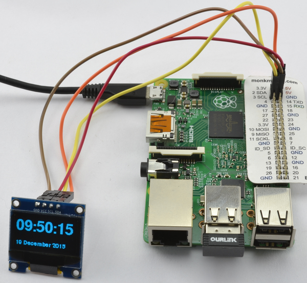
To make this recipe, you need:
Four female-to-female jumper wires (see “Prototyping Equipment”)
I2C OLED display 128×64 pixels (see “Modules”)
Some of these displays have just four pins, whereas others have eight pins. The 8-pin varieties (including Adafruit’s displays) have more pins because they have both an I2C and SPI interfaces. The 4-pin displays just have an I2C. The I2C interface is better suited for use with the Raspberry Pi because the display operates at 5V, and both interface pins for I2C (SDA and SCL) are 3.3V outputs from the Raspberry Pi, whereas the SPI interface’s MISO pin is a 3.3V input that requires level conversion before connecting to the Raspberry Pi.
The connections between the Raspberry Pi and the module are as follows:
For this recipe to work, you will also need to set up your Raspberry Pi for I2C, so follow Recipe 9.3 first.
Adafruit has a library for these displays. Install it by using these commands:
$ git clone https://github.com/adafruit/Adafruit_Python_SSD1306.git $ cd Adafruit_Python_SSD1306 $ sudo python setup.py install
This library uses the Python Image Library (PIL), which can be installed by using the command:
$ sudo pip install pillow
The code example old_clock.py displays the time and date on the OLED display. As with all the program examples in this book, you can also download the program from the Code section of the Raspberry Pi Cookbook website.
fromoled.deviceimportssd1306fromoled.renderimportcanvasfromPILimportImageFontimporttimefromdatetimeimportdatetime# Set up displaydevice=ssd1306(port=1,address=0x3C)font_file='/usr/share/fonts/truetype/freefont/FreeSansBold.ttf'small_font=ImageFont.truetype('FreeSans.ttf',12,filename=font_file)large_font=ImageFont.truetype('FreeSans.ttf',33,filename=font_file)# Display a message on 3 lines, first line big fontdefdisplay_message(top_line,line_2):globaldevicewithcanvas(device)asdraw:draw.text((0,0),top_line,font=large_font,fill=255)draw.text((0,50),line_2,font=small_font,fill=255)whileTrue:now=datetime.now()date_message='{:%d%B %Y}'.format(now)time_message='{:%H:%M:%S}'.format(now)display_message(time_message,date_message)time.sleep(0.1)
Every I2C slave device has an address, which is set in the line:
device=ssd1306(port=1,address=0x3C)
This is fixed at 3C (hex) for many of the low-cost I2C modules but may vary, so you should check any documentation that comes with the device or use I2C tools (Recipe 9.4) to list all the I2C devices attached to the bus so that you can see the address of your display.
Small, organic LED (OLED) displays are cheap, don’t use much current, and have high resolution despite their diminutive size. They are replacing LCD displays in many consumer products.
The instructions here are for 4-pin I2C interfaces. If you really want to use the SPI interface, then take a look at Adafruit’s tutorial on this.
Use an LED strip based on the WS2812 RGB LED chips on your Raspberry Pi.
Using these LED strips (Figure 14-8) can be really easy, with a direct connection to the Raspberry Pi and power for the LEDs supplied by the Raspberry Pi. This is the “Happy Day” scenario that should work just fine, but do see the Discussion for this recipe for potential pitfalls with this approach and ways to guarantee that your LED strip use is trouble-free.
While it might be tempting to power the LEDs from the 3.3V supply pin on the GPIO connector, do not do this—it can only supply low currents (see Recipe 9.2). Using this pin could easily damage your Raspberry Pi.
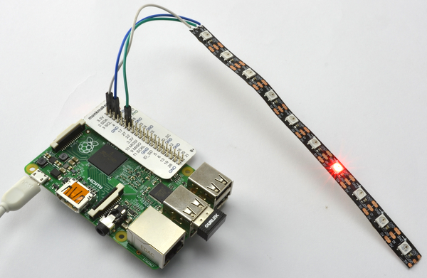
The LED strip used in Figure 14-8 is cut from a reel. In this case, there are 10 LEDs. As each LED can use up to 60mA, 10 is probably a sensible limit for the number of LEDs that can be used without arranging for a separate power supply for the LED strip (see Discussion).
To connect the strip to the Raspberry Pi, jumper wires with female connectors on one end were cut and the wire ends soldered to the three connections on the LED strip: GND, DI (Data In), and 5V. These can then be attached to GPIO pins GND, GPIO 18, and 5V, respectively.
Notice that the LED strip has an arrow printed on it (Figure 14-9). Make sure that when you solder leads to the LED strip, you start from the cut end to the left of the arrow.
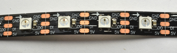
Finding a library for the WS2812 that works with all Raspberry Pi models is, at the time of writing, a little tricky. The original library was developed by Jeremy Garff, and Raspberry Pi 2 support was added to this by Richard Hurst. Adafruit also had a hand in the library. However, Raspbian’s switch to Linux Kernel 4.1.6 broke a few things. At the time of writing, the Pimoroni Unicorn HAT (which uses a modified version of Richard Hurst’s library) seems to be most reliable. Being tied to a commercial product, this version is most likely to be maintained for any future changes to Raspbian or Raspberry Pi boards. To install this library, run the following commands:
$ git clone https://github.com/pimoroni/unicorn-hat.git $ cd unicorn-hat/python/rpi-ws281x $ make $ sudo python setup.py install
The following example program (led_strip.py) will set the LED red in successive positions along the strip. As with all the program examples in this book, you can also download the program from the Code section of the Raspberry Pi Cookbook website.
importtimefromneopixelimport*# LED strip configuration:LED_COUNT=10# Number of LED pixels.LED_PIN=18# GPIO pin connected to the pixels (must support PWM!).LED_FREQ_HZ=800000# LED signal frequency in hertz (usually 800khz)LED_DMA=5# DMA channel to use for generating signal (try 5)LED_BRIGHTNESS=255# Set to 0 for darkest and 255 for brightestLED_INVERT=False# True to invert the signalRED=Color(255,0,0)NO_COLOR=Color(0,0,0)strip=Adafruit_NeoPixel(LED_COUNT,LED_PIN,LED_FREQ_HZ,LED_DMA,LED_INVERT,LED_BRIGHTNESS)strip.begin()defclear():foriinrange(0,LED_COUNT):strip.setPixelColor(i,NO_COLOR)strip.show()i=0whileTrue:clear()strip.setPixelColor(i,RED)strip.show()time.sleep(1)i+=1ifi>=LED_COUNT:i=0
The parameters in the section LED strip configuration can be modified for different LED configurations. If you have a different number of LEDs in your strip, then modify LED_COUNT. The rest of the constants do not need to be changed.
Each of the LEDs can have its color set independently using the setPixelColor method. The first parameter to this is the index position (starting at 0) of the LED whose color you want to set. The second parameter is the color to set it to. The changes to the LED colors are not actually updated until the method show is called.
Each LED in the strip can use a maximum of about 60mA. It will only do this if all three color channels (red, green, and blue) are at maximum brightness (255). So, if you plan to use a lot of LEDs, then you will need to use a separate 5V power supply sufficient to supply all the LEDs in your strip. Figure 14-10 shows how you would wire up a separate power supply. A female DC jack-to-screw terminal adapter (“Prototyping Equipment”) makes it easy to connect an external power supply to a breadboard.
The datasheet for the WS2812 states that the input signal should have a logic high of at least 4V for a 5V power supply to the LEDs. So, when using this with a Raspberry Pi’s 3.3V GPIO output, there are no guarantees that the LEDs will work reliably. Having said that, I have never had any trouble.
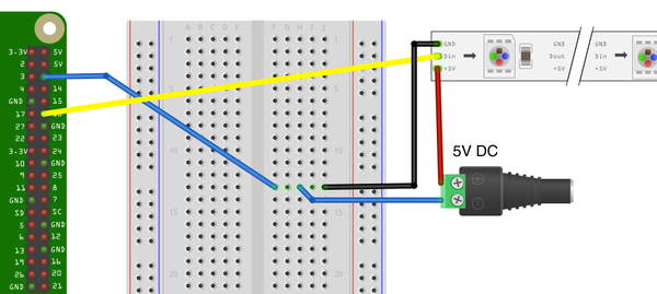
If you do have problems with the signal not being strong enough, you can use a single transistor logic-level converter as shown in Figure 14-11. A suitable transistor is the 2N7000 (note that a 2N3904 will not work in this situation as it cannot respond quickly enough to invert the pulses).
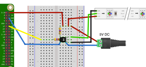
This transistor converts the 3.3V signal to 5V but has the side effect of inverting the signal, so if the output of the GPIO pin is HIGH, the signal into the LED strip will be LOW and vice-versa. This means that the logic in your program will need to be modified by changing the line:
LED_INVERT=False
to read:
LED_INVERT=True
An alternative to using a transistor to raise the signal level from 3.3V to 5V is to use a level converter module (see Recipe 9.13).
The Unicorn HAT, whose library is used here, has 64 WS2812 LEDs arranged in an 8×8 grid. You can find out more about this display at https://shop.pimoroni.com/products/unicorn-hat.
The Internet of Things (IoT) is the rapidly growing network of devices (things) connected to the Internet. That doesn’t just mean more and more computers using browsers, but actual appliances and wearable and portable technology. This includes all sorts of home automation from smart appliances and lighting, to security systems and even Internet-operated pet feeders, as well as lots of less practical but fun projects.
In this chapter, you will learn how your Raspberry Pi can participate in the Internet of Things in various ways.
Use the bottle Python web server library (Recipe 7.17) to create an HTML web interface to control the GPIO port.
To make this recipe, you will need:
Breadboard and jumper wires (see “Prototyping Equipment”)
Three 1kΩ resistors (see “Resistors and Capacitors”)
Three LEDs (see “Opto-Electronics”)
Tactile push switch (see “Miscellaneous”)
The breadboard layout for this is shown in Figure 15-1.
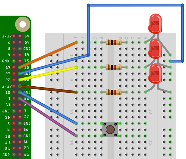
An alternative to using a breadboard is to attach a Raspberry Squid and Squid Button (see Recipe 9.10 and Recipe 9.11). These can be plugged directly into the GPIO pins of the Raspberry Pi, as shown in Figure 15-2.
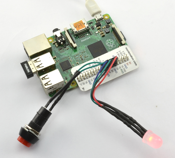
To install the bottle library, see Recipe 7.17.
Open an editor (nano or IDLE) and paste in the following code. As with all the program examples in this book, you can also download the program from the Code section of the Raspberry Pi Cookbook website, where it is called web_control.py. You will also find a program called web_control_test.py. This program simply tests the hardware by flashing the LEDs in sequence and displaying the state of the switch, without any of the complications of the web server.
Here’s the web_control.py program:
frombottleimportroute,runimportRPi.GPIOasGPIOGPIO.setmode(GPIO.BCM)led_pins=[18,23,24]led_states=[0,0,0]switch_pin=25GPIO.setup(led_pins[0],GPIO.OUT)GPIO.setup(led_pins[1],GPIO.OUT)GPIO.setup(led_pins[2],GPIO.OUT)GPIO.setup(switch_pin,GPIO.IN,pull_up_down=GPIO.PUD_UP)defswitch_status():state=GPIO.input(switch_pin)ifstate:return'Up'else:return'Down'defhtml_for_led(led):l=str(led)result=" <input type='button' onClick='changed("+l+")' value='LED "+l+"'/>"returnresultdefupdate_leds():fori,valueinenumerate(led_states):GPIO.output(led_pins[i],value)@route('/')@route('/<led>')defindex(led):ifled>='0'andled<='9':led_num=int(led)led_states[led_num]=notled_states[led_num]update_leds()response="<script>"response+="function changed(led)"response+="{"response+=" window.location.href='/' + led"response+="}"response+="</script>"response+='<h1>GPIO Control</h1>'response+='<h2>Button='+switch_status()+'</h2>'response+='<h2>LEDs</h2>'response+=html_for_led(0)response+=html_for_led(1)response+=html_for_led(2)returnresponsetry:run(host='0.0.0.0',port=80)finally:('\nCleaning up')GPIO.cleanup()
You must run the program as superuser:
sudopythonweb_control.py
If it starts correctly, you should see a message like this:
Bottleserverstartingup(usingWSGIRefServer())...Listeningonhttp://0.0.0.0:80/HitCtrl-Ctoquit.
Open a browser window from any machine on your network, even the Raspberry Pi itself, and navigate to the IP address of the Raspberry Pi. The web interface shown in Figure 15-3 should appear.
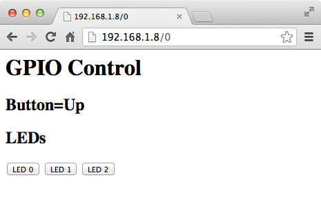
If you click on one of the three LED buttons at the bottom of the screen, you should find that the appropriate LED toggles on and off.
Also, if you hold down the button as you reload the web page, you should see that the text next to Button says Down rather than Up.
To understand how the program works, we first need to look at how a web interface works. All web interfaces rely on a server somewhere (in this case, a program on the Raspberry Pi) responding to requests from a web browser.
When the server receives a request, it looks at the information that comes with the request and formulates some HyperText Markup Language (HTML) in response.
If the web request is just to the root page (http://192.168.1.8/), then led will be given a default value of n. However, if we were to browse the URL http://192.168.1.8/2, then the 2 on the end of the URL would be assigned to the led parameter.
The led parameter is then used to determine that LED 2 should be toggled.
To be able to access this LED-toggling URL, we need to arrange things so that when the button for LED 2 is pressed, the page is reloaded with this extra parameter on the end of the URL. The trick here is to include a JavaScript function in HTML that is returned to the browser. When the browser runs this function, it causes the page to be reloaded with the appropriate extra parameter.
This all means that we have the rather mind-bending situation where the Python program is generating code in JavaScript to be run later by the browser. The lines that generate this JavaScript function are as follows:
response = "<script>"
response += "function changed(led)"
response += "{"
response += " window.location.href='/' + led"
response += "}"
response += "</script>"
Rather than repeat the HTML for each of the buttons, this is generated by the function html_for_led:
defhtml_for_led(led):l=str(led)result=" <input type='button' onClick='changed("+l+")'value='LED " + l + "'/>"returnresult
This code is used three times, once for each button, and links a button press with the changed function. The function is also supplied with the LED number as its parameter.
The code that actually changes the GPIO outputs lives in the update_leds function. This function is called every time the server receives a request that includes an LED number that requires toggling:
defupdate_leds():fori,valueinenumerate(led_states):GPIO.output(led_pins[i],value)
The function simply iterates over an array of states, setting each output in turn to its current value.
The following line in the index function toggles the value in the state array for the LED supplied in the led parameter:
led_states[led_num]=notled_states[led_num]
The process of reporting the state of the push button is much more straightforward. It is simply the act of reading the state of the input and generating HTML that reports the button position. This is all contained in the switch_status function:
defswitch_status():state=GPIO.input(switch_pin)ifstate:return'Up'else:return'Down'
For more information on using bottle, see the bottle documentation.
Use the bottle web server and some fancy JavaScript to automatically update your display.
The example shown in Figure 15-4 displays the Raspberry Pi’s CPU temperature using its built-in sensor.
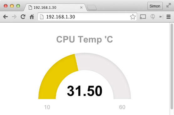
To install the bottle library, see Recipe 7.17.
There are four files for this example, which are contained in the folder web_sensor:
Contains the Python code for the bottle server
Contains the web page that will be displayed in your browser
A third-party JavaScript library that displays the temperature meter
A library used by the justgage library
As with all the program examples in this book, you can also download the program from the Code section of the Raspberry Pi Cookbook website.
To run the program, change directory to web_sensor and then run the Python program using:
$ sudo python web_sensor.py
Then open a browser, either on the same Raspberry Pi or any computer on the same network as the Raspberry Pi, and enter the IP address of the Raspberry Pi into the browser’s address bar. The page shown in Figure 15-4 should appear.
The main program (web_sensor.py) is actually quite concise:
importos,timefrombottleimportroute,run,templatedefcpu_temp():dev=os.popen('/opt/vc/bin/vcgencmd measure_temp')cpu_temp=dev.read()[5:-3]returncpu_temp@route('/temp')deftemp():returncpu_temp()@route('/')defindex():returntemplate('main.html')@route('/raphael')defindex():returntemplate('raphael.2.1.0.min.js')@route('/justgage')defindex():returntemplate('justgage.1.0.1.min.js')run(host='0.0.0.0',port=80)
The function cpu_temp reads the temperature of the Raspberry Pi’s CPU, as described in Recipe 13.9.
Four routes are then defined for the bottle web server. The first (/temp) returns a string containing the CPU temperature in degrees C. The root route (/) returns the main HTML template for the page (main.html). The other two routes provide access to copies of the raphael and justgage JavaScript libraries.
The file main.html mostly contains the JavaScript to render the user interface.
<html><head><scriptsrc="http://ajax.googleapis.com/ajax/libs/jquery/1.7.2/jquery.min.js"type="text/javascript"charset="utf-8"></script><scriptsrc="raphael"></script><scriptsrc="justgage"></script><script>functioncallback(tempStr,status){if(status=="success"){temp=parseFloat(tempStr).toFixed(2);g.refresh(temp);setTimeout(getReading,1000);}else{alert("There was a problem");}}functiongetReading(){$.get('/temp',callback);}</script></head><body><divid="gauge"class="200x160px"></div><script>varg=newJustGage({id:"gauge",value:0,min:10,max:60,title:"CPU Temp 'C"});getReading();</script></body></html>
The JQuery, Raphael, and JustGage libraries are all imported (JQuery from https://developers.google.com/speed/libraries/#jquery and the other two from local copies).
Getting a reading from the Raspberry Pi to the browser window is a two-stage process. First, the function getReading is called. This sends a web request with the route /temp to web_sensor.py and specifies a function called callback to be run when the web request completes. The callback function is then responsible for updating the JustGage display before setting a timeout to call getReading again after a second.
For an example of using Tkinter to display sensor values in an application rather than a web page, see Recipe 13.19.
The JustGage library has all sorts of useful options for displaying sensor values. See http://justgage.com/ for more information.
Have your Raspberry Pi send requests to the If This Then That (IFTTT) Maker channel to trigger configurable notifications.
This recipe is illustrated with an example that sends you an email when the CPU temperature of your Raspberry Pi exceeds a threshold.
You need to create an account with IFTTT before you can start using it, so visit www.ifttt.com and sign up.
The next step is to create a new IFTTT recipe. Rather confusingly, IFTTT uses the word recipe to refer to a rule, such as When I get a web request from a Raspberry Pi, send an email. Click on the Create a Recipe button. This will prompt you to first enter the IF part of the recipe and later the THAT part.
In this case, the IF THIS part (the trigger) is going to be the receipt of a web request from your Raspberry Pi, so click on THIS and then enter Maker into the search field to find the Maker channel. Select the Maker channel and when prompted to Choose a Trigger, select the option (Receive a Web Request). This will open the form shown in Figure 15-5.
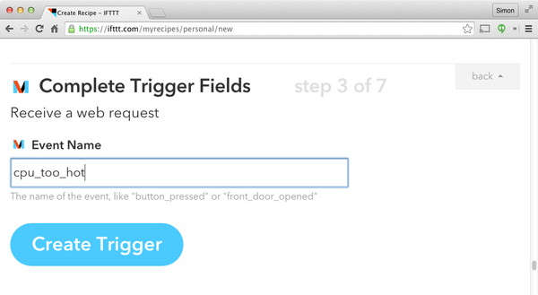
Enter the text cpu_too_hot into the Event Name field and click Create Trigger.
This will now move you to the THAT portion of the recipe, the action , and you will need to select an action channel. Here there are many options, but for this example you will use the Email channel, so type Email into the search field and then select the Email channel. You will see several email-related channels, including Gmail. Use the email channel, even if you are sending from a Gmail account.
Having selected the Email channel, select the action Send Me an Email, and the form shown in Figure 15-6 will be displayed.
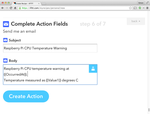
Change the text so that it appears as shown in Figure 15-6. Note that the special values OccurredAt and Value1 will both be surrounded by {{ and }}. These values are called ingredients and are variable values that will be taken from the web request and substituted into the email subject and body.
Click Create Action and then Create Recipe to finish the recipe creation.
That’s it—the recipe is now live, and once the Raspberry Pi is ready to send web requests to it, it will start emailing.
The Python program to send the web request can be found with the downloads for the book on the Raspberry Pi Cookbook website and is called ifttt_cpu_temp.py.
importtime,os,urllib,urllib2MAX_TEMP=37.0MIN_T_BETWEEN_WARNINGS=60# MinutesEVENT='cpu_too_hot'BASE_URL='https://maker.ifttt.com/trigger/'KEY='cyR3vPNFlP9K32W4NZB9cd'defsend_notification(temp):data=urllib.urlencode({'value1':str(temp)})url=BASE_URL+EVENT+'/with/key/'+KEYresponse=urllib2.urlopen(url=url,data=data)(response.read())defcpu_temp():dev=os.popen('/opt/vc/bin/vcgencmd measure_temp')cpu_temp=dev.read()[5:-3]returnfloat(cpu_temp)whileTrue:temp=cpu_temp()("CPU Temp (C): "+str(temp))iftemp>MAX_TEMP:("CPU TOO HOT!")send_notification(temp)("No more notifications for: "+str(MIN_T_BETWEEN_WARNINGS)+" mins")time.sleep(MIN_T_BETWEEN_WARNINGS*60)time.sleep(1)
Before running the program, you will need to get an access key for the Maker Action channel by selecting Channels (at the top of the IFTTT web page), and then searching for Maker. Connect to the channel, and then you will see your key displayed near the bottom of the web page (Figure 15-7).
Paste the key into ifttt_cpu_temp.py on the line that starts KEY= and then run the program using:
$ sudo python ifttt_cpu_temp.py
You can increase your CPU temperature by playing a video or temporarily wrapping your Raspberry Pi in bubble wrap. Once the event is triggered, you should receive an email that looks like Figure 15-8. Notice how the values have been substituted into the email.
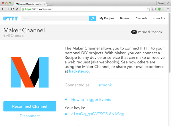
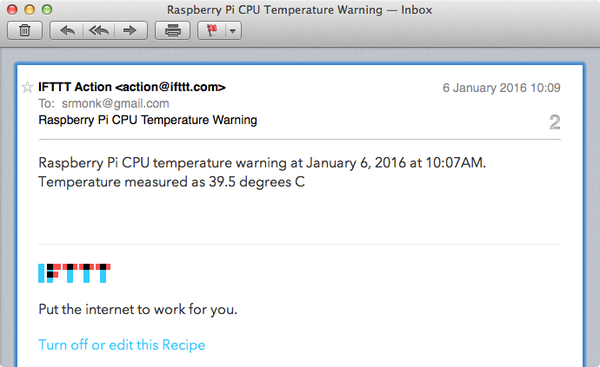
Most of the action for this program takes place in the send_notification email. This first constructs a URL including the key and request parameter value1 (containing the temperature) and then uses the Python urllib2 to send the web request to IFTTT.
The main loop continually checks the temperature against the MAX_TEMP, and if the CPU temperature exceeds MAX_TEMP, the web request is sent and a long sleep is started as specified by MIN_T_BETWEEN_WARNINGS to prevent your inbox from being flooded with notifications.
As an alternative to using IFTTT, you could, of course, just send an email directly using Recipe 7.16. However, by using IFTTT to send the messages, you are not restricted to email notifications—you could use any of the action channels available in IFTTT without having to write any code.
To send an email directly from Python, see Recipe 7.16.
The code to measure the CPU temperature is described in Recipe 13.9.
You could just use Recipe 15.3 and change the Action Channel to be Twitter. However, the ThingSpeak service is an alternative way of doing this.
ThingSpeak is similar to IFTTT but is aimed squarely at IoT projects. It allows you to create channels that can store and retrieve data using web requests, and also has a number of actions, including ThingTweet, which provides a web services wrapper around Twitter. This is easier to use than the Twitter API, which requires you to register your application with Twitter.
Start by visiting https://thingspeak.com and signing up. Then select the ThingTweet action (Figure 15-9). You will be prompted to log in to Twitter.
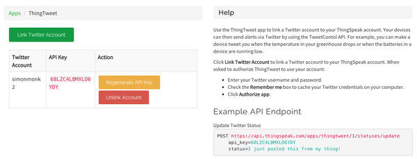
The Python program to send the web request that triggers the tweet can be found with the downloads for the book on the Raspberry Pi Cookbook website and is called send_tweet.py:
importtime,os,urllib,urllib2MAX_TEMP=37.0MIN_T_BETWEEN_WARNINGS=60# MinutesBASE_URL='https://api.thingspeak.com/apps/thingtweet/1/statuses/update/'KEY='68LZC4LBMXLO6YDY'defsend_notification(temp):status='Raspberry Pi getting hot. CPU temp='+tempdata=urllib.urlencode({'api_key':KEY,'status':status})response=urllib2.urlopen(url=BASE_URL,data=data)(response.read())defcpu_temp():dev=os.popen('/opt/vc/bin/vcgencmd measure_temp')cpu_temp=dev.read()[5:-3]returncpu_tempwhileTrue:temp=cpu_temp()("CPU Temp (C): "+str(temp))iftemp>MAX_TEMP:("CPU TOO HOT!")send_notification(temp)("No more notifications for: "+str(MIN_T_BETWEEN_WARNINGS)+" mins")time.sleep(MIN_T_BETWEEN_WARNINGS*60)time.sleep(1)
As with Recipe 15.3, you will need to paste your key from Figure 15-9 into the code before you run the program. Run and test the program in just the same way you did in Recipe 15.3.
The code is very similar to Recipe 15.3. The main difference is in the function send_notification, which constructs the tweet and then sends the web request with the message as the parameter status.
For full documentation of the ThingSpeak service, see https://uk.mathworks.com/help/thingspeak/.
In Recipe 15.5, you use the popular Cheerlights, implemented in ThingSpeak; and i Recipe 15.6, you learn how to use ThingSpeak to collect sensor data.
You want to hook your Raspberry Pi up to an RGB LED and participate in the popular Cheerlights project.
Cheerlights is a web service that, when anyone sends a tweet to @cheerlights containing the name of a color, will record that color as being the last color. Around the world, many people have Cheerlight projects that use a web service to request the last color and set their lighting to that color. So when anyone tweets, everyone’s lights change color.
Use a Raspberry Squid RGB LED connected to your Raspberry Pi (Figure 15-10) and run the test program called cheerlights.py, which can be found with the downloads for the book on the Raspberry Pi Cookbook website.

fromsquidimport*importurllib,timesquid=Squid(18,23,24)cheerlights_url="http://api.thingspeak.com/channels/1417/field/2/last.txt"try:whileTrue:try:cheerlights=urllib.urlopen(cheerlights_url)c=cheerlights.read()cheerlights.close()(c)squid.set_color_rgb(c)except:('Error')time.sleep(2)finally:GPIO.cleanup()
Before running the program, you will need to install the Squid library (see Recipe 9.10).
Your LED should immediately set itself to the last color. It will probably change color after a while as someone tweets; if it doesn’t, try tweeting a message such as “@cheerlights red” and the color of both your LED and the rest of the world’s LEDs should all change. Valid color names for Cheerlights are red, blue, cyan, white, oldlace, purple, magenta, yellow, orange, and pink.
The code just sends a web request to ThingSpeak, which returns a string of colors as a 6-digit hexadecimal number. This is then used to set the LED color.
The inner try/except code is used to ensure that the program does not crash if there is a temporary network outage.
Cheerlights uses ThingSpeak to store the last color in a channel. In Recipe 15.6, a channel is used to record sensor data.
If you don’t have a Squid, you can use an RGB on a breadboard (see Recipe 10.10), or even adapt Recipe 14.7 to control an entire LED strip.
Log into ThingSpeak, and from the Channels drop-down, select My Channels. Now create a new channel by completing the top of the form as shown in Figure 15-11.
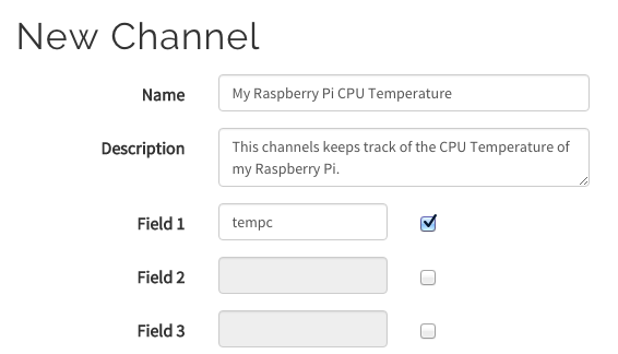
The rest of the form can be left blank. When you have finished editing, click Save Channel at the bottom of the page. Click on the Data Import/Export tab to find a summary of the web requests that you can use, customized to the channel you just created (Figure 15-12).
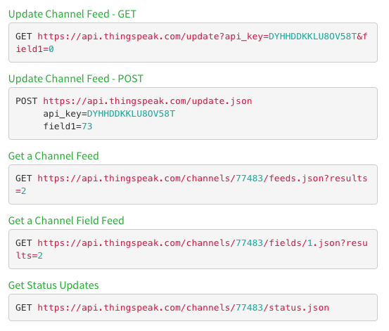
To send data to the channel, a web request must be sent. The Python program to send the web request can be found with the downloads for the book on the Raspberry Pi Cookbook website and is called thingspeak_data.py.
importtime,os,urllib,urllib2PERIOD=60# SecondsBASE_URL='https://api.thingspeak.com/update.json'KEY='DYHHDDKKLU8OV58T'defsend_data(temp):data=urllib.urlencode({'api_key':KEY,'field1':temp})response=urllib2.urlopen(url=BASE_URL,data=data)(response.read())defcpu_temp():dev=os.popen('/opt/vc/bin/vcgencmd measure_temp')cpu_temp=dev.read()[5:-3]returncpu_tempwhileTrue:temp=cpu_temp()("CPU Temp (C): "+str(temp))send_data(temp)time.sleep(PERIOD)
Run the program. On the ThingSpeak channel page on the Private View tab, you should see a graph like the one shown in Figure 15-13.
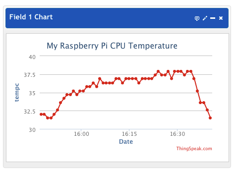
This will update as a new reading arrives every minute.
The variable PERIOD is used to determine the time interval between each sending of the temperature. This period is in seconds.
The send_data function constructs the web request, supplying the temperature in a parameter called field1.
If your data might be of public interest—say, accurate environmental readings—then you might want to make the channel public so that anyone can make use of it. This probably isn’t the case for your Pi’s CPU temperature.
For an example of exporting sensor data into a spreadsheet, see Recipe 13.20.
For an explanation of the code that reads the CPU temperature, see Recipe 13.9.
You want your Raspberry Pi to perform some action in response to a certain hashtag or mention in a tweet.
Recipe 15.5 does just this, but it does it very inefficiently because it relies on you continually polling with web requests to see if the color has changed.
An efficient mechanism for monitoring tweets that does not rely on polling is to use IFTTT (see Recipe 15.3) to spot tweets of interest and then send a web request to a service called Dweet that can push notifications to a Python program running on your Raspberry Pi (Figure 15-14).
For example, you could flash an LED for 10 seconds every time there is a mention of your username on Twitter by using a Raspberry Squid or an LED attached to a breadboard.
As far as the hardware goes, this recipe just requires some electronics that do something noticeable when GPIO 18 goes high. This could be one channel of a Raspberry Squid (see Recipe 9.10) or a single LED attached to breadboard (see Recipe 10.1) or for ultimate flexibility, a relay (see Recipe 10.6). Using a relay would allow you to create a project like Bubblino.
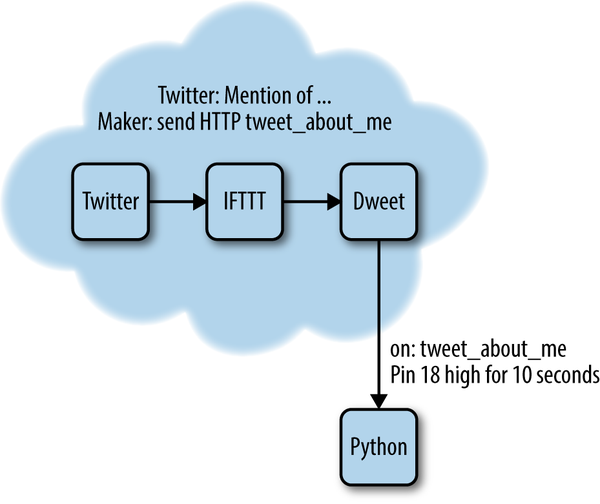
The first step is to log in to IFTTT (see Recipe 15.3) and then create a new recipe. Choose an action channel of New Mention of You and then click Create Trigger. For the recipe’s action channel, select Maker and then select the action “Make a Web Request” and complete the fields as shown in Figure 15-15.
The URL includes a request parameter with the ingredient of text. This will contain the body of the tweet. Although this will not be used other than to print it in the console, you might have the message displayed on an LCD screen for a more sophisticated project, so it is useful to know how to pass data from tweet to the Python program.
Then click Create Recipe to take the IFTTT recipe live.
The dweet.io web service operates rather like Twitter for IoT things. It has a web interface that allows you to both post and listen for dweets.
Dweet does not require an account or any login details to make use of it; you can just have one thing (IFTTT in this case) send a message to it and have another thing (your Raspberry Pi Python program) wait for notifications from it that something you are interested in has happened. In this case, the token that links the two is tweet_about_me. This is not very unique, and if several people are trying out this example from the book at the same time, then they will get each other’s messages. To avoid this, use a more unique token (say, by adding a random string of letters and numbers to the message).
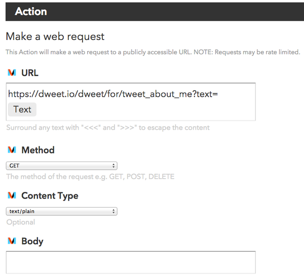
To access Dweet from your Python program, the dweepy library needs to be installed, using the following commands:
$ git clone git://github.com/paddycarey/dweepy.git $ cd dweepy $ sudo python setup.py install
The program for this recipe can be found with the downloads for the book on the Raspberry Pi Cookbook website and is called twitter_trigger.py.
importtimeimportdweepyimportRPi.GPIOasGPIOKEY='tweet_about_me'OUTPUT_PIN=18OUTPUT_DURATION=10GPIO.setmode(GPIO.BCM)GPIO.setup(OUTPUT_PIN,GPIO.OUT)whileTrue:try:fordweetindweepy.listen_for_dweets_from(KEY):('Tweet: '+dweet['content']['text'])GPIO.output(OUTPUT_PIN,True)time.sleep(OUTPUT_DURATION)GPIO.output(OUTPUT_PIN,False)exceptException:pass
The program uses the listen_for_dweets_from method to leave an open connection to the dweet.io server, listening for any push messages from the server as a result of a dweet arriving from IFTTT in response to a tweet. The try/except block ensure that if there is any communication outage, the program will just start the listenning process again.
For a similar project using a different approach, see Recipe 15.5.
While a Raspberry Pi is ideal for projects that need a network connection or a graphical user interface, the low-power GPIO outputs and lack of any analog inputs puts it at a disadvantage to microcontroller boards, such as the Arduino (Figure 16-1). Fortunately, it is possible to have the best of both worlds by connecting an Arduino to a Raspberry Pi and allowing the Arduino to interface with external electronics.
Arduino boards are superficially a little like a Raspberry Pi in that they are small and essentially a computer. However, Arduino boards are very different from the Raspberry Pi in a number of respects:
They do not have any interface to keyboard, mouse, or screen.
They have just 2 KB of RAM and 32 KB of flash for storing programs.
Their processor runs at just 16 MHz compared with the Raspberry Pi’s 700 MHz.
This might lead you to wonder why you would use such an apparently feeble board rather than the Raspberry Pi directly.
The answer is that Arduino boards, the most common being the Arduino Uno, are better than the Raspberry Pi at interfacing with external electronics in several ways. For example, Arduino boards have:
14 digital inputs/outputs, like the Raspberry Pi’s GPIO pins, but each pin can provide up to 40 mA compared with the original Raspberry Pi’s 3 mA. This enables them to power more devices without the need for extra electronics.
6 analog inputs. This makes connecting analog sensors much easier (see Recipe 16.7).
6 PWM outputs. These outputs are hardware-timed and produce a much more accurate PWM signal than can be achieved with the Raspberry Pi, making them a lot better for controlling servo motors.
A huge range of plug-in shields for everything from motor control to LCD displays of various sorts.
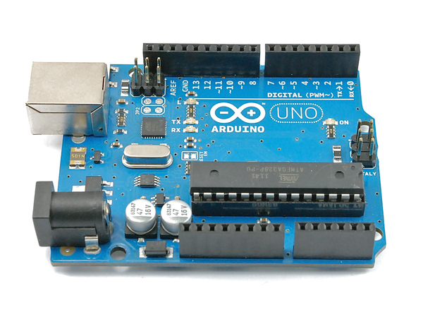
In many ways, using a Raspberry Pi with an Arduino to handle all the low-level stuff is a good combination, playing to the strengths of both boards. This is taken to its extreme with interface boards that have a GPIO connector and also include Arduino-compatible hardware such as the aLaMode (Recipe 16.13).
Be sure to check out the accompanying video for this recipe at http://razzpisampler.oreilly.com.
The Arduino IDE is available for the Raspberry Pi. It is a little bit slow, but usable. You will definitely want to use the superior speed of the Raspberry Pi 2 when using the Arduino IDE. Use these commands to install the Arduino IDE:
$ sudo apt-get update $ sudo apt-get install arduino
After installation, you will find an Electronics group in your Programs menu (Figure 16-2).
To program the Arduino IDE, connect it to the Raspberry Pi through its USB cable. The easiest way to set up your Pi to use the Arduino IDE is to run a script created by Kevin Osborn that configures the serial ports and Arduino profiles necessary to get things running. This has the advantage that it also sets up the aLaMode board to be ready for use (Recipe 16.13).
To download and run this script, follow these steps:
$ https://github.com/wyolum/alamode/raw/master/bundles/alamode-setup.tar.gz $ tar -xvzf alamode-setup.tar.gz $ cd alamode-setup $ sudo ./setup
You can now connect your Arduino to your Raspberry Pi. From the Tools menu, select Board and set the board type to Arduino Uno. Then, from the Serial Port option, select /dev/ttyACM0. To upload a test program that will make the LED on the Arduino blink, select the File menu and then click “Examples, Basic,” and finally click Blink. Click on the right arrow on the toolbar to begin the compile and upload process. If all is well, you should see a “Done Uploading” message in the status area at the bottom of the IDE window.
If you find that the device ttyACM0 is not listed even though your Arduino is plugged in, try restarting the Arduino IDE. If that doesn’t work, then you may have to reboot your Raspberry Pi. Leave the Arduino connected while you reboot and restart the Arduino IDE.
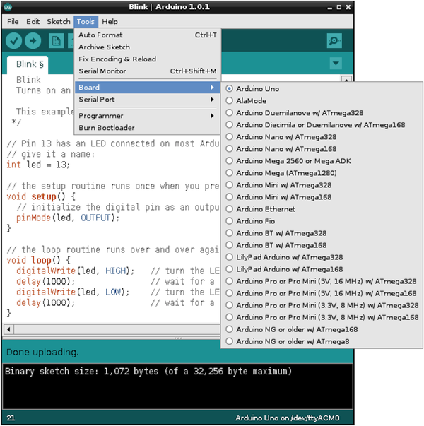
To get the most out of using Arduino with Raspberry Pi, you need to learn a little Arduino programming. You may find the book Programming Arduino: Getting Started with Sketches (McGraw-Hill/Tab Books), by yours truly, helpful.
You can, however, make use of an Arduino without needing to write any code on the Arduino side, using a project called PyFirmata. Recipe 16.3 explains how to use PyFirmata.
The Arduino IDE setup script came from the blog Bald Wisdom.
The Arduino IDE includes a feature called the serial monitor, which allows you to both send text messages to the Arduino and see messages from the Arduino over the USB cable.
To try this out, you first need to write a very short Arduino program (programs are called sketches in the Arduino world). This sketch will just repeat a message, sending it every second.
The Arduino sketch is listed here. As with all the program examples in this book, you can also download the program from http://www.raspberrypicookbook.com, where it is contained in the folder ArduinoHello. Just follow the link to this book and then click Code.
Use File→New to create a new sketch, and paste the following text into it before uploading it to the Arduino.
voidsetup(){Serial.begin(9600);}voidloop(){Serial.println("Hello Raspberry Pi");delay(1000);}
As soon as the sketch is uploaded onto the Arduino, it will start sending the message “Hello Raspberry Pi” over serial. You won’t see this until you open the serial monitor (Figure 16-3) by clicking the icon that looks like a magnifying glass on the right of the toolbar.
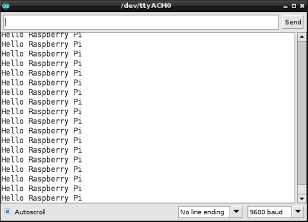
The serial monitor has a drop-down list in the bottom-right corner, where you can select the baud rate (speed of communication). If this isn’t already set to 9600, change it to that value.
In some of the later recipes in this chapter (Recipes 16.10 and 16.11), you look at writing your own custom code to communicate with Python programs running on the Raspberry Pi so that you don’t need to have the Arduino IDE running.
A more generic approach is to use something called PyFirmata, which avoids the need for any programming on the Raspberry Pi. See Recipe 16.3 for details.
Arduino is quite easy to learn; here are some links to books and online resources to get you started:
Programming Arduino: Getting Started with Sketches (Tab Books) by Simon Monk
Arduino Cookbook (O’Reilly) by Michael Margolis
Connect the Arduino to a USB socket of the Raspberry Pi so that the computer can communicate and send power to the Arduino.
Next, install the Firmata sketch onto the Arduino and the PyFirmata onto your Raspberry Pi. This entails installing the Arduino IDE, so if you haven’t already done so, follow Recipe 16.1.
The Arduino IDE includes Firmata, so all you have to do to install Firmata onto your Arduino board is to upload a sketch. You will find the sketch at File→Examples→Firmata→StandardFirmata.
Once Firmata is installed, the Arduino waits for communication from the Raspberry Pi.
Now you need to install PyFirmata, the other half of the link. This requires the use of the PySerial library, so follow Recipe 9.6 to install this.
You can now download and install PyFirmata by using these commands:
$ git clone https://github.com/tino/pyFirmata.git $ cd pyFirmata $ sudo python setup.py install
You can try out the PyFirmata library from the Python console. Enter the following commands to turn on the built-in LED on Arduino pin 13 (marked with an L) and then turn it off again.
$ sudo python Python 2.7.3 (default, Jan 13 2013, 11:20:46) [GCC 4.6.3] on linux2 Type "help", "copyright", "credits" or "license" for more information.
>>>importpyfirmata>>>board=pyfirmata.Arduino('/dev/ttyACM0')>>>pin13=board.get_pin('d:13:o')>>>pin13.write(1)>>>pin13.write(0)>>>board.exit()
The preceding code first imports the PyFirmata library and then makes an instance of Arduino called board, using the USB interface (/dev/ttyACM0) as its parameter. You can then gain a reference to one of the Arduino pins (in this case, 13) and set it to be a digital output. The d is for digital, 13 is the pin number, and o is for output.
To set the output pin high, use write(1), and to set it low, use write(0). You can also use True and False in place of 1 and 0.
Figure 16-4 shows an Arduino with the rows of connections down both sides of the board.
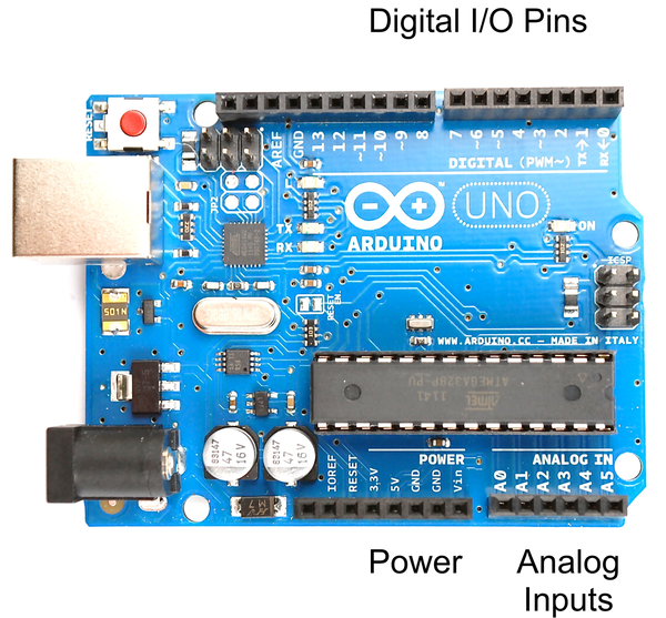
The pins at the top marked 0 to 13 can be used as digital inputs or outputs. Some of these pins are also used for other things. Pins 0 and 1 are used as a serial interface, and are in use when the USB port is being used; and pin 13 is attached to the on-board LED marked with an L. The digital I/O pins 3, 5, 6, 9, 10, and 11 have a ~ symbol next to them that indicates that they can be used for PWM output (see Recipe 10.3).
On the other side of the board, there is one set of connectors that supplies power at 5V and 3.3V, and six analog inputs marked A0 to A5.
An Arduino Uno on its own uses about 50 mA, which, given that the Raspberry Pi itself is probably using about 10 times that, makes it perfectly possible to power the Arduino from the USB connection of the Raspberry Pi. However, if you start attaching a lot of external electronics to the Arduino, and the current consumption increases, then you may want to power the Arduino from its own power adapter by using the DC barrel socket. This will accept 7V to 12V DC.
The only real downside of using Firmata is that because all instructions have to come from the Raspberry Pi, it doesn’t make much use of Arduino’s ability to run independently. For advanced projects, you will probably end up writing your own Arduino code that receives instructions from the Raspberry Pi and/or sends messages to the Raspberry Pi while it gets on with other tasks.
In Recipe 16.3, you flashed the built-in LED (labeled with an L) on the Arduino board. Here, you build on this to attach an external LED and write a short Python program to make it blink.
To make this recipe, you need:
Arduino Uno (see “Modules”)
Breadboard and jumper wires (see “Prototyping Equipment”)
270Ω resistor (see “Resistors and Capacitors”)
LED (see “Opto-Electronics”)
As an alternative to using a breadboard and an LED, you could plug in one color channel of a Squid RGB LED (Recipe 9.10).
Connect the breadboard, fastening the components to the Arduino as shown in Figure 16-5.
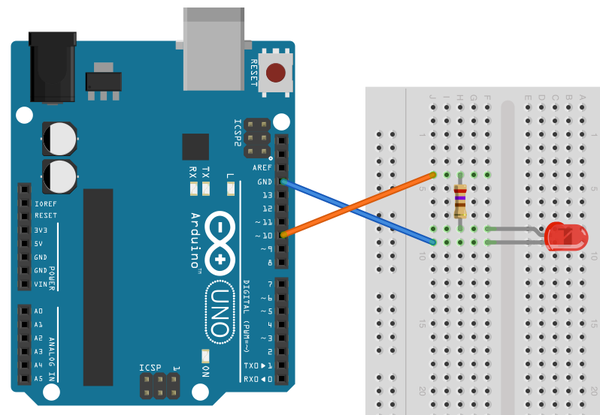
If you haven’t already done so, follow Recipe 16.3 to set up PyFirmata.
The following Python script makes the LED blink at a rate of about 1 Hz. Open an editor (nano or IDLE) and paste in the following code. As with all the program examples in this book, you can also download the program from the Code section of http://www.raspberrypicookbook.com, where it is called ardu_flash.py.
importpyfirmataimporttimeboard=pyfirmata.Arduino('/dev/ttyACM0')led_pin=board.get_pin('d:10:o')whileTrue:led_pin.write(1)time.sleep(0.5)led_pin.write(0)time.sleep(0.5)
This is very similar to connecting an LED to a Raspberry Pi (Recipe 10.1). However, note that since Arduino outputs can supply a lot more current than Raspberry Pi outputs, you can use a smaller value resistor and make the LED a bit brighter. Arduino outputs are also 5V rather than 3.3V.
If you want the user interface to control the LED like you had in Recipe 10.8 (and shown in Figure 16-6), it’s pretty straightforward to modify the code. You can find the modified program, called ardu_gui_switch.py, on the book’s website. Remember, this will not work from the SSH command line. You need to have access to the Raspberry Pi’s graphical environment so that you can see the user interface.

See Recipe 10.1 for controlling an LED directly from a Raspberry Pi.
Use a level converter to connect the RXD pin of the Raspberry Pi to the Tx pin of the Arduino, and the TXD pin of the Raspberry Pi to the Rx pin of the Arduino.
To make this recipe, you need:
Arduino Uno (see “Modules”)
Breadboard and jumper wires (see “Prototyping Equipment”)
270Ω and 470Ω resistors (see “Resistors and Capacitors”) or a four-way bidirectional level converter (see “Modules”)
If you are using the level converter module, connect the breadboard as shown in Figure 16-7.
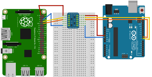
If, on the other hand, you are using the pair of resistors, then connect the breadboard as shown in Figure 16-8.
The Arduino Rx input is fine with just 3.3V from the Raspberry Pi TXD pin; however, the 5V coming from the Arduino Tx pin must be dropped to the 3V expected by the Raspberry Pi.
You will need to set up PyFirmata—see Recipe 16.3. The Arduino side of the project remains exactly the same as Recipe 16.4, where USB is used instead of the serial connection. There is one change that you need to make to the Python program running on the Raspberry Pi—change the device name from /dev/ttyACM0 to /dev/ttyAMA0, as the serial port has a different device name from the USB interface.
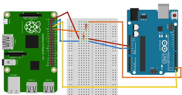
The following Python script makes the LED blink at a rate of about 1 Hz. Open an editor (nano or IDLE) and paste in the following code. As with all the program examples in this book, you can also download the program from the Code section of http://www.raspberrypicookbook.com, where it is called ardu_flash_ser.py.
importpyfirmataimporttimeboard=pyfirmata.Arduino('/dev/ttyAMA0')led_pin=board.get_pin('d:13:o')whileTrue:led_pin.write(1)time.sleep(0.5)led_pin.write(0)time.sleep(0.5)
The level conversion is necessary because the Raspberry Pi serial port connections, RXD and TXD, operate at 3.3V, whereas the Arduino Uno operates at 5V. While it is OK for the 5V Arduino to use a 3.3V signal, the reverse is not true and a 5V signal connected to the 3.3V RXD pin is likely to damage the Raspberry Pi.
Use PyFirmata to read a digital input on the Arduino.
To make this recipe, you need:
Arduino Uno (see “Modules”)
Breadboard and jumper wires (see “Prototyping Equipment”)
1kΩ resistor (see “Resistors and Capacitors”)
Tactile push switch (see “Miscellaneous”)
Connect the breadboard, fastening the components to the Arduino as shown in Figure 16-9.
If you haven’t already done so, follow Recipe 16.3 to set up PyFirmata.
The following Python script prints out a message every time the switch is pressed. It’s very similar to the program in (switch.py). Open an editor (nano or IDLE) and paste in the following code. As with all the program examples in this book, you can also download the program from the Code section of http://www.raspberrypicookbook.com, where it is called ardu_switch.py. Just follow the link to this book and then click Code.
importpyfirmataimporttimeboard=pyfirmata.Arduino('/dev/ttyACM0')switch_pin=board.get_pin('d:4:i')it=pyfirmata.util.Iterator(board)it.start()switch_pin.enable_reporting()whileTrue:input_state=switch_pin.read()ifinput_state==False:('Button Pressed')time.sleep(0.2)
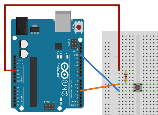
When you run it, nothing will happen for a second or two, while the Firmata sketch starts and establishes communication with the Raspberry Pi. But, once it starts up, each time you press the button, a message will appear:
$ sudo python ardu_switch.py Button Pressed Button Pressed Button Pressed
PyFirmata uses the concept of an Iterator to monitor the Arduino input pin. The reasons for this are bound up in the implementation of Firmata. This means that you can’t simply read the value of an Arduino input pin on demand; instead, you have to create a separate Iterator thread that manages the reading of the switch by using the commands:
it=pyfirmata.util.Iterator(board)it.start()
You then also have to enable reporting for the pin you are interested in by using the command:
switch_pin.enable_reporting()
A side effect of this mechanism is that when you press Ctrl-C to exit the program, it won’t exit properly. There is no nice way to kill the Iterator thread other than to open another Terminal window or SSH session and kill the process (Recipe 3.26).
If the only Python process running is this program, you can kill it with the command:
$ sudo killall python
Simply disconnecting the Arduino from the Raspberry Pi, which will break the communication link, will also cause the Python program to exit.
This is very similar to connecting a switch directly to a Raspberry Pi (Recipe 12.1), and if you just have one switch, there is no real benefit in using an Arduino like this.
Use PyFirmata to read an analog input on the Arduino.
To make this recipe, you need:
Arduino Uno (see “Modules”)
Breadboard and jumper wires (see “Prototyping Equipment”)
10kΩ trimpot (see “Resistors and Capacitors”)
Connect the breadboard, holding the components to the Arduino as shown in Figure 16-10.
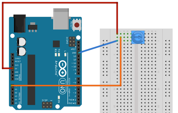
If you haven’t already done so, follow Recipe 16.3 to set up PyFirmata.
The following Python script (ardu_adc.py) will display both the raw reading from the analog input and the voltage at the analog input. It is very similar to the program in (adc_test.py).
Open an editor (nano or IDLE) and paste in the following code. As with all the program examples in this book, you can also download the program from the Code section of http://www.raspberrypicookbook.com, where it is called ardu_adc.py.
importpyfirmataimporttimeboard=pyfirmata.Arduino('/dev/ttyACM0')analog_pin=board.get_pin('a:0:i')it=pyfirmata.util.Iterator(board)it.start()analog_pin.enable_reporting()whileTrue:reading=analog_pin.read()ifreading!=None:voltage=reading*5.0("Reading=%f\tVoltage=%f"%(reading,voltage))time.sleep(1)
The analog reading will be a value between 0.0 and 1.0:
$ sudo python ardu_adc.py Reading=0.000000 Voltage=0.000000 Reading=0.165200 Voltage=0.826000 Reading=0.784000 Voltage=3.920000 Reading=1.000000 Voltage=5.000000
The program is very similar to that of Recipe 16.6. An Iterator must be used, and the same problems of stopping the program apply.
The if statement is needed, because if the first read is made before the actual reading from the analog input has happened, then the read will return None rather than a number. The if statement effectively causes the program to ignore any null readings.
To use digital inputs, see Recipe 16.6.
Use PyFirmata to send commands to an Arduino to generate a PWM signal on one of its outputs.
To make this recipe, you need:
Arduino Uno (see “Modules”)
Breadboard and jumper wires (see “Prototyping Equipment”)
270Ω resistor (see “Resistors and Capacitors”)
LED (see “Opto-Electronics”)
Connect the breadboard, holding the components to the Arduino as shown in Figure 16-11.
If you haven’t already done so, follow Recipe 16.3 to set up PyFirmata.

The following Python script (ardu_pwm.py) will prompt you to enter a value for the PWM power and then set the LED brightness accordingly. Open an editor (nano or IDLE) and paste in the following code. As with all the program examples in this book, you can also download the program from the Code section of http://www.raspberrypicookbook.com, where it is called ardu_pwm.py.
importpyfirmataboard=pyfirmata.Arduino('/dev/ttyACM0')led_pin=board.get_pin('d:10:p')whileTrue:duty_s=raw_input("Enter Brightness (0 to 100):")duty=int(duty_s)led_pin.write(duty/100.0)
With the value entered as 100, the LED should be at full brightness. The brightness decreases as the number decreases:
$ sudo python ardu_pwm.py Enter Brightness (0 to 100):100 Enter Brightness (0 to 100):50 Enter Brightness (0 to 100):10 Enter Brightness (0 to 100):5 Enter Brightness (0 to 100):
The sketch for this is actually very straightforward. You define the output as PWM output using the command:
led_pin=board.get_pin('d:10:p')
The p is for PWM. But remember, this only works on Arduino pins marked with a ~ symbol.
We can also modify the slider control (Figure 16-12) so that it will operate through PyFirmata. You can download this sketch as ardu_gui_slider.
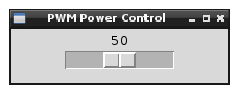
Although an Arduino can deliver 40 mA to an output—roughly 10 times the current available on a Raspberry Pi GPIO pin, it’s still not enough to directly drive a motor or high-power LED module. For these, you would need to use the circuit described in Recipe 11.4, modified to use an Arduino output pin rather than a Raspberry Pi GPIO pin.
Use PyFirmata to send commands to an Arduino to generate the pulses necessary to control the position of a servo motor.
To make this recipe, you need:
Arduino Uno (see “Modules”)
Breadboard and jumper wires (see “Prototyping Equipment”)
1kΩ resistor (see “Resistors and Capacitors”)
LED (see “Integrated Circuits”)
Connect the breadboard as shown in Figure 16-13.
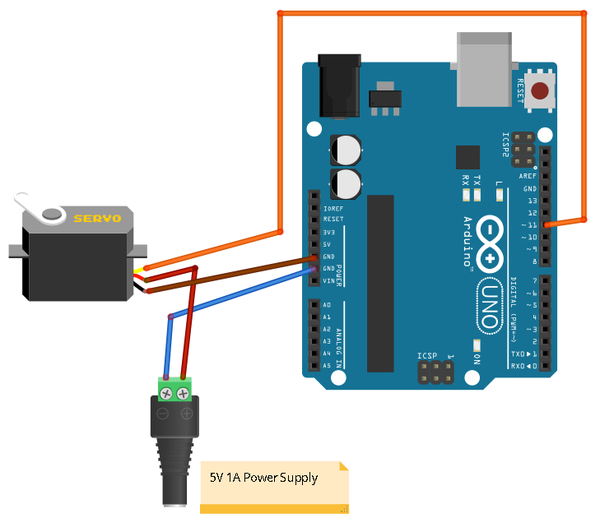
If you have not already done so, follow Recipe 16.3 to set up PyFirmata.
The following Python script (ardu_servo.py) will prompt you to enter a value for the servo’s angle and then set the arm of the servo motor accordingly.
Open an editor (nano or IDLE) and paste in the following code. As with all the program examples in this book, you can also download the program from the Code section of http://www.raspberrypicookbook.com, where it is called ardu_servo.py.
importpyfirmataboard=pyfirmata.Arduino('/dev/ttyACM0')servo_pin=board.get_pin('d:11:s')whileTrue:angle_s=raw_input("Enter Angle (0 to 180):")angle=int(angle_s)servo_pin.write(angle)
With the value entered as 0, the servo should be at one end of its travel. Changing this to 180 sends it to the other end, and 90 puts it somewhere in the middle:
$ sudo python ardu_servo.py Enter Angle (0 to 180):0 Enter Angle (0 to 180):180 Enter Angle (0 to 180):90
The sketch for this is actually very straightforward. You define the output as a servo output by using the command:
led_pin=board.get_pin('d:11:s')
The s is for servo. This can be used on any of the Arduino digital pins.
If you’ve built Recipe 11.1, you will notice that, by comparison, there is no jitter of the servo when used with an Arduino in this way.
Use a level converter or pair of resistors to connect the RXD pin of the Raspberry Pi to the Tx pin of the Arduino, and the TXD pin of the Raspberry Pi to the Rx pin of the Arduino.
To make this recipe, you will need:
Arduino Uno (see “Modules”)
Breadboard and jumper wires (see “Prototyping Equipment”)
270Ω and 470Ω resistors (see “Resistors and Capacitors”) or a four-way bidirectional level converter (see “Modules”)
10kΩ trimpot (see “Resistors and Capacitors”)
If you are using the level converter module, then connect the breadboard as shown in Figure 16-14.
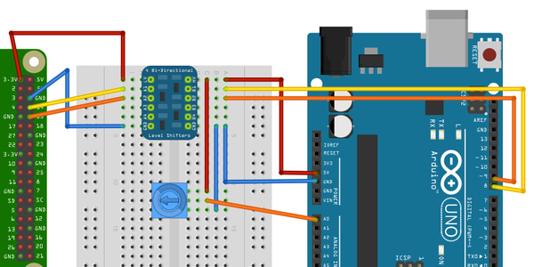
If, on the other hand, you are using the pair of resistors, then connect the breadboard as shown in Figure 16-15.
The Arduino Rx input is fine with just 3.3V from the Raspberry Pi TXD pin; however, the 5V coming from the Arduino Tx pin must be dropped to the 3V expected by the Raspberry Pi.
You will need to disable serial port logging and install PySerial by following Recipe 9.6.
The following Python script (ardu_pi_serial.py) will prompt you to enter a command of either l or r. If you enter l, then the built-in Arduino LED will toggle on and off. If, on the other hand, you enter r, the Arduino will read the analog value from its analog input A0 and send back a number between 0 and 1023 as the reading.
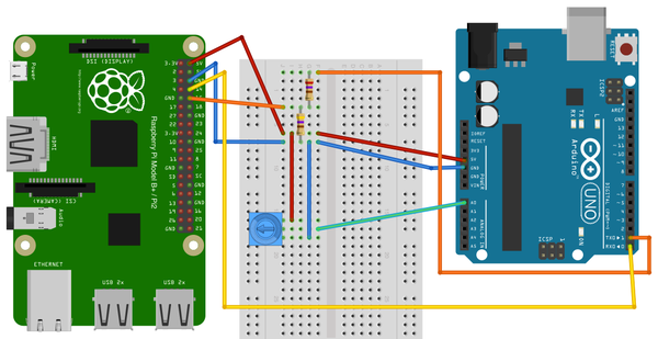
Open an editor (nano or IDLE) and paste in the following code. As with all the program examples in this book, you can also download the program from the Code section of http://www.raspberrypicookbook.com, where it is called ardu_pi_serial.py.
importserialser=serial.Serial('/dev/ttyAMA0',9600)whileTrue:command=raw_input("Enter command: l - toggle LED, r - read A0 ")ifcommand=='l':ser.write('l')elifcommand=='r':ser.write('r')(ser.readline())
You also need to upload the following sketch, ArduinoSerial, onto your Arduino Uno. You can paste it into a new sketch window, and it is available with the rest of this book’s programs for download.
#include "SoftwareSerial.h"intledPin=13;intanalogPin=A0;SoftwareSerialser(8,9);// RX, TXbooleanledOn=false;voidsetup(){ser.begin(9600);pinMode(ledPin,OUTPUT);}voidloop(){if(ser.available()){charch=ser.read();if(ch=='l'){toggleLED();}if(ch=='r'){sendAnalogReading();}}}voidtoggleLED(){ledOn=!ledOn;digitalWrite(ledPin,ledOn);}voidsendAnalogReading(){intreading=analogRead(analogPin);ser.println(reading);}
Run the program and test that the built-in L LED on the Arduino toggles on and off using the l command. Then try setting the trimpot to different positions and take analog readings by sending the r command:
$ sudo python ardu_pi_serial.py Enter command: l - toggle LED, r - read A0 l Enter command: l - toggle LED, r - read A0 l Enter command: l - toggle LED, r - read A0 r 0 Enter command: l - toggle LED, r - read A0 r 540 Enter command: l - toggle LED, r - read A0 r 1023
The code in the Python program uses the PySerial library to open a connection onto the serial port. The main program loop then repeatedly asks for commands and processes them, in both cases by writing the single-character command to the serial port. In the case of the r command, it also reads a line from the serial connection and then prints it.
Note that, despite appearances, here the result of serial.readline is a string. If you need to convert this into a number, you can use the function int to convert it. For example:
line=ser.readline()value=int(line)
The Arduino sketch is a little more complicated. The example sketch provided can easily be modified to add more inputs or outputs and respond to more commands.
This sketch does not use the Arduino’s hardware serial port, as this is generally used by its USB connection. Instead, an Arduino library called SoftwareSerial is used to allow pins 8 and 9 to be used as Rx and Tx, respectively.
As with all Arduino sketches, there must be a setup function that is called one time when the Arduino starts up and a loop function is called repeatedly.
The setup function begins serial communication and sets the pin for the built-in LED (on Arduino pin 13) to be an output.
The loop function first checks to see if any serial messages have arrived by using the ser.available function call. If there is a message to process, it reads the character, and the following if clauses call the appropriate helper function to process the command.
For more information about the SoftwareSerial library, see http://arduino.cc/en/Reference/SoftwareSerial.
The alternative to writing your own custom code for communication is to use PyFirmata (Recipe 16.3).
In addition to communicating over serial, you can communicate with the Arduino using I2C (Recipe 16.11).
The I2C bus has the concept of master and slave devices. The master device controls the bus and a number of slave devices can be connected to one master, with each slave having its own address.
You will install a sketch on the Arduino that makes it an I2C slave device and use the SMBus Python library to write an I2C program for the Raspberry Pi. The SDA, SCL, and ground connections of both devices need to be connected to each other, and the Arduino powered separately or from the 5V supply of the Raspberry Pi.
To make this recipe, you need:
Arduino Uno (see “Modules”)
Male-to-female jumper wires (see “Prototyping Equipment”)
Connect the breadboard, holding the components to the Arduino as shown in Figure 16-16.
The Arduino board used here is the latest Arduino Uno R3. If you have an older board that doesn’t have the two dedicated SCL and SDA pins, then you can connect the Raspberry Pi SDA and SCL pins to Arduino pins A4 and A5.
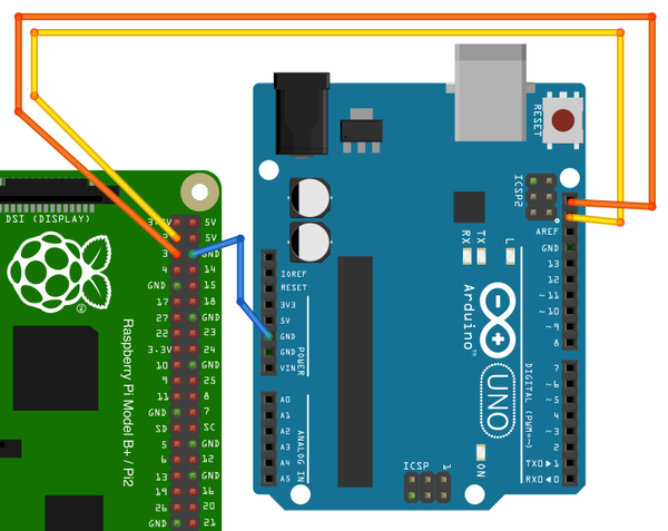
Install the following sketch onto the Arduino. You can find it, named ArduinoI2C, in the program downloads for this book at http://www.raspberrypicookbook.com.
#include <Wire.h>intSLAVE_ADDRESS=0x04;intledPin=13;intanalogPin=A0;booleanledOn=false;voidsetup(){pinMode(ledPin,OUTPUT);Wire.begin(SLAVE_ADDRESS);Wire.onReceive(processMessage);Wire.onRequest(sendAnalogReading);}voidloop(){}voidprocessMessage(intn){charch=Wire.read();if(ch=='l'){toggleLED();}}voidtoggleLED(){ledOn=!ledOn;digitalWrite(ledPin,ledOn);}voidsendAnalogReading(){intreading=analogRead(analogPin);Wire.write(reading>>2);}
You need to follow Recipe 9.3 to set up Raspberry Pi for I2C communication.
Open an editor (nano or IDLE) and paste in the following code. As with all the program examples in this book, you can also download the program from the Code section of http://www.raspberrypicookbook.com, where it is called ardu_pi_i2c.py.
importsmbusimporttime# for RPI revision 1, use "bus = smbus.SMBus(0)"bus=smbus.SMBus(1)# This must match what's in the Arduino SketchSLAVE_ADDRESS=0x04defrequest_reading():reading=int(bus.read_byte(SLAVE_ADDRESS))(reading)whileTrue:command=raw_input("Enter command: l - toggle LED, r - read A0 ")ifcommand=='l':bus.write_byte(SLAVE_ADDRESS,ord('l'))elifcommand=='r':request_reading()
The test program is very similar to the one used to demonstrate serial communication in Recipe 16.10. It’s designed to show communication in both directions. Entering the l command toggles the Arduino’s built-in LED on and off, and using the r command reports a reading from the Arduino’s A0 analog input. You can use a male-to-male jumper wire to connect A0 to 3.3V, 5V, or GND on the Arduino to get different readings:
$ sudo python ardu_pi_i2c.py Enter command: l - toggle LED, r - read A0 l Enter command: l - toggle LED, r - read A0 l Enter command: l - toggle LED, r - read A0 r 184 Enter command: l - toggle LED, r - read A0
The Arduino acts as the I2C slave in this arrangement and must therefore be given an address so that the master running on the Raspberry Pi can identify it if there is more than one slave device connected. In this case, the address is set to 0x04 and held in the SLAVE_ADDRESS variable.
The setup function in the Arduino then sets up two callback functions that will be used. The function processMessage will be invoked whenever the onReceive event occurs. This will happen whenever a command is sent from the Raspberry Pi. The other callback function, sendAnalogReading, is associated with the onRequest event. This occurs when the Raspberry Pi requests data, and will read the analog value, divide it by four to make it fit into a single byte, and then send it back to the Raspberry Pi.
The Python counterpart to this sketch first creates a new instance of SMBus called bus. This takes a single argument of 1. This is the I2C port on the Raspberry Pi to be used. This will be 1 unless you are using the very first version of the Raspberry Pi (revision 1). These boards have a black audio connector rather than the light blue connector of the revision 2 boards. If you have one of these older boards, use 0 as the argument here. The I2C port available at the GPIO connector was swapped between these two revisions.
The program prompts the user for a command (l or r). If the command is l, it writes the character l to the Arduino, which in turn causes the onReceive handler (processMessage) to be run. This in turn will call toggleLED.
If, on the other hand, the user enters the r command, then the request_reading function will be called. This will call read_byte in the SMBus library, which will cause the onRequest event in the Arduino sketch to be invoked.
You may be wondering why it is OK to connect the 5V Arduino directly to the I2C connections of the Raspberry Pi, without the level converter module that you had to use for serial communications (see Recipe 16.5). The reason is that the I2C bus standard operates at whatever voltage the pull-up resistors connected to SDA and SCL use. In this case, the Arduino Uno has no pull-up resistors connected to the I2C lines. These are provided by the Raspberry Pi, which pulls them up to 3.3V.
Although the Arduino has no pull-up resistors on the I2C lines, this is not true of all I2C devices. If the I2C device operates at 5V, make sure that it has no pull-up resistors (but if it does, you can usually remove them relatively easily).
For the serial equivalent to this setup, see Recipe 16.10.
Use one of the small breadboard-friendly Arduino boards.
Figure 16-17 shows an Arduino Pro Mini board. Boards like this have the great advantage that they can be plugged directly into the breadboard along with other components needed for the project. The Pro Mini board is also available in a 3.3V version, which avoids any need for level conversion when you’re using it with a Raspberry Pi.
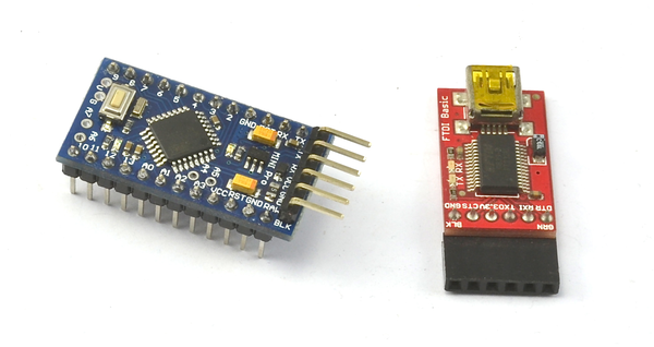
Some of these boards, such as the Pro Mini shown in Figure 16-17, require a USB programming interface. You can program them from the Raspberry Pi, or another computer if that proves problematic.
In addition to official Arduino boards, you can also find many low-cost clones that can make a great companion to the Raspberry Pi.
The aLaMode board (see Table A-3) shown in Figure 16-18 is a wonderful board that is essentially an Arduino Uno with a Raspberry Pi GPIO socket in one corner. The aLaMode fits neatly onto the Raspberry Pi and allows you to use Arduino shields without the need for lots of extra wires. Although designed for the original Raspberry Pi, this board can also be used with the Raspberry Pi 2.
Note that the board in Figure 16-18 is shown without the header sockets needed to attach Arduino shields.
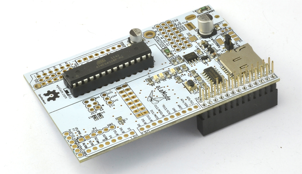
The installation instructions in Recipe 16.1 will also set up aLaMode in your Arduino environment. From the Tools menu of the Arduino IDE, choose Board and then ALaMode (Figure 16-19).
You also need to set the serial port to /devttyS0 before programming the aLaMode, which takes place through the serial connection.
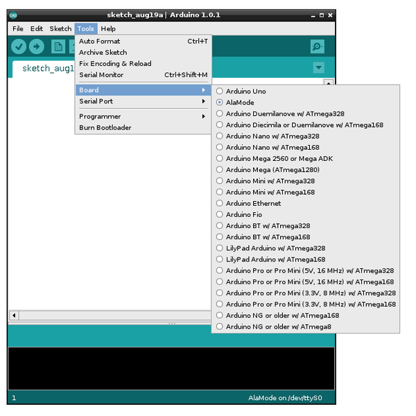
All the Firmata recipes in this chapter will work with the aLaMode, along with the custom serial communication example of Recipe 16.10. The only modification necessary is in the Python programs communicating with the aLaMode, as they must use the serial port rather than the USB port.
The aLaMode is hardwired to the Arduino’s Tx and Rx pins with built-in level conversion.
When using Firmata, you need to change the port from /dev/ttyACM0 to /dev/ttyAMA0:
board = pyfirmata.Arduino('/dev/ttyAMA0')
Similarly, if you are writing your own custom code, you will need to change the line that opens the serial connection so that it looks like this:
ser=serial.Serial('/dev/ttyAMA0',9600)
To try the aLaMode, just load the Standard Firmata sketch onto the aLaMode and then run the Python program ardu_flash_ser.py (Recipe 16.5).
Some of the interesting features of the aLaMode board are:
It can be powered from the 5V line of the Raspberry Pi GPIO connector or a separate 5V power adapter connected to its micro-USB socket.
The RTC is connected directly to the Raspberry Pi rather than the Arduino side of the board.
Arduino shields can be attached, with a high degree of compatibility (Recipe 16.14).
It can be an I2C slave. In addition to being linked by serial, the aLaMode’s I2C connections are also connected to those of the Raspberry Pi (Recipe 16.11).
It has a micro SD card reader.
It has headers for direct connection to servo motors (Recipe 16.9).
The aLaMode does suffer from one minor design flaw—with the Arduino shield headers soldered in place, the analog inputs A0 to A5 can easily touch the bare metal of the RJ45 Ethernet socket of the Raspberry Pi. To avoid this, place a couple of layers of electrical insulating tape over the top surface of the Ethernet socket on the Raspberry Pi before attaching the aLaMode (Figure 16-20).
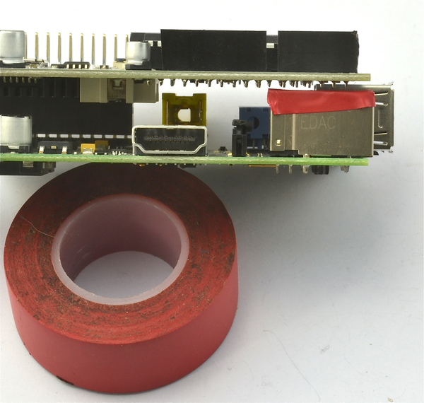
The official aLaMode instructions can be found at http://bit.ly/1d2YMxh.
Use an aLaMode interface board. You may find that the board requires the Arduino-style header sockets for shields to be soldered into place.
As an example, you’ll connect an Arduino LCD shield to the aLaMode (Figure 16-21).
To make this recipe, you need:
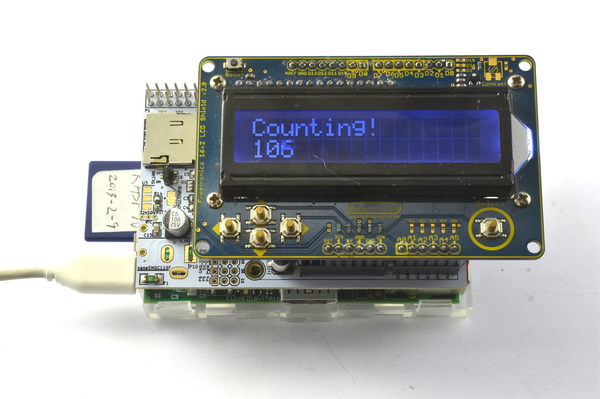
As with all the program examples in this book, you can also download this sketch from the Code section of http://www.raspberrypicookbook.com, where it is called AlaModeShield.
#include <LiquidCrystal.h>// pins for Freetronics LCD ShieldLiquidCrystallcd(8,9,4,5,6,7);voidsetup(){lcd.begin(16,2);lcd.("Counting!");}voidloop(){lcd.setCursor(0,1);lcd.(millis()/s1000);}
Simply upload the sketch onto the aLaMode and you should see the message “Counting” appear on the top row of the display, while the bottom row should show a number that counts the seconds.
This example used the Freetronics LCD shield. There are a number of other LCD display shields, and some have different pin allocations. If you use a different module, you’ll need to change the line:
LiquidCrystal lcd(8, 9, 4, 5, 6, 7);
The parameters are the Arduino pins to be used for the following LCD connections: rs, enable, d4, d5, d6, and d7, in that order.
The reference material for the Arduino LiquidCrystal library can be found at http://arduino.cc/en/Reference/LiquidCrystal.
The following tables will help you to find the parts used in this book. Where possible, I have listed product codes for a few suppliers.
There are now many electronic component suppliers that cater to the maker and electronics hobbyist. Some of the most popular are listed in Table A-1.
| Supplier | Website | Notes |
|---|---|---|
|
Adafruit |
Good for modules |
|
|
Digikey |
Wide range of components |
|
|
MakerShed |
Good for modules, kits, and tools |
|
|
MCM Electronics |
Wide range of components |
|
|
Mouser |
Wide range of components |
|
|
SeeedStudio |
Interesting low-cost modules |
|
|
SparkFun |
Good for modules |
|
| MonkMakes | http://www.monkmakes.com | Electronic Kits for Raspberry Pi, etc. |
| Pimoroni | UK-based manufacturer of interesting HATs and retailer | |
| Polulu | https://www.pololu.com/ | Great for motor controllers and robots |
|
CPC |
UK-based; wide range of components |
|
|
Ciseco |
Suppliers of PiLite, Humble Pi, etc. |
|
|
Farnell |
International; wide range of components |
|
|
Maplin |
UK-based; bricks and mortar component and Pi store |
|
|
Proto-pic |
UK-based; stock SparkFun and Adafruit modules |
The other great source of components is eBay.
Searching for components can be time-consuming and difficult. The Octopart component search engine can be very helpful in tracking down parts. MonkMakes, Adafruit, and Sparkfun all have packs of components to get you started.
Many of the hardware projects in this book use jumper wires of various sorts. Male-to-female leads (to connect the Raspberry Pi GPIO connector to a breadboard) and male-to-male (to make connections on the breadboard) are particularly useful. Female-to-female are occasionally useful for connecting modules directly to GPIO pins. You rarely need leads longer than 3 inches (75mm). Table A-2 lists some jumper wire and breadboard specifications, along with their suppliers.
A handy way to get started with a breadboard, jumper wires, and some basic components is to buy a starter kit like the Electronics Starter Kit for Raspberry Pi by MonkMakes.com.
| Description | Suppliers |
|---|---|
|
M-M jumper wires |
SparkFun: PRT-08431; Adafruit: 759 |
|
M-F jumper wires |
SparkFun: PRT-09140; Adafruit: 825 |
|
F-F jumper wires |
SparkFun: PRT-08430; Adafruit: 794 |
|
Half-sized breadboard |
SparkFun: PRT-09567; Adafruit: 64 |
|
Pi Cobbler |
Adafruit: 1105 |
| Raspberry Leaf (26 pin) | Adafruit: 1772 |
| Raspberry Leaf (40 pin) | Adafruit: 2196 |
| Electronics Starter Kit for Raspberry Pi | Amazon; monkmakes.com |
| Adafruit PermaProto for Pi (half breadboard) | Adafruit: 1148 |
| Adafruit PermaProto for Pi (full breadboard) | Adafruit: 1135 |
| Adafruit PermaProto HAT | Adafruit: 2314 |
| DC barrel jack-to-screw terminal adapter (female) | Adafruit: 368 |
Table A-3 shows resistors and capacitors used in this cookbook and some suppliers.
| Part | Suppliers |
|---|---|
|
270Ω 0.25W resistor |
Mouser: 293-270-RC |
|
470Ω 0.25W resistor |
Mouser: 293-470-RC |
|
1kΩ 0.25W resistor |
Mouser: 293-1k-RC |
|
3.3kΩ 0.25W resistor |
Mouser: 293-3.3k-RC |
|
4.7kΩ 0.25W resistor |
Mouser: 293-4.7k-RC |
|
10 kΩ trimpot |
Adafruit: 356; SparkFun: COM-09806; Mouser: 652-3362F-1-103LF |
|
Photoresistor |
Adafruit: 161; SparkFun: SEN-09088 |
|
330nF capacitor |
Mouser: 80-C330C334K5R |
| Thermistor T0 of 1k Beta 3800 NTC | Mouser: 871-B57164K102J (Note: Beta is 3730) |
Table A-4 lists transistors and diodes used in this cookbook and some suppliers.
| Part | Suppliers |
|---|---|
|
FQP30N06L N-channel logic level MOSFET transistor |
Mouser: 512-FQP30N06L; Sparkfun: COM-10213 |
|
2N3904 NPN bipolar transistor |
SparkFun: COM-00521; Adafruit: 756 |
|
1N4001 diode |
Mouser: 512-1N4001; SparkFun: COM-08589; Adafruit: 755 |
| TIP120 Darlington transistor | Adafruit: 976; CPC: SC10999 |
| 2N7000 MOSFET transistor | Mouser: 512-2N7000; CPC: SC06951 |
Table A-5 lists integrated circuits used throughout this cookbook and some suppliers.
| Part | Suppliers |
|---|---|
|
7805 voltage regulator |
SparkFun: COM-00107; Adafruit: 2164; Mouser: 511-L7805CV, CPC: SC10586 |
|
L293D motor driver |
SparkFun: COM-00315; Adafruit: 807; Mouser: 511-L293D; CPC: SC10241 |
|
ULN2803 Darlington driver IC |
SparkFun: COM-00312; Adafruit: 970; Mouser: 511-ULN2803A; CPC: SC08607 |
|
DS18B20 temperature sensor |
SparkFun: SEN-00245; Adafruit: 374; Mouser: 700-DS18B20; CPC: SC10426 |
|
MCP3008 eight-channel ADC IC |
Adafruit: 856; Mouser: 579-MCP3008-I/P; CPC: SC12789 |
|
TMP36 temperature sensor |
SparkFun: SEN-10988; Adafruit: 165; Mouser: 584-TMP36GT9Z; CPC: SC10437 |
Table A-6 lists opto-electronic cooptmponents used throughout this cookbook and some suppliers.
| Part | Suppliers |
|---|---|
|
5mm red LED |
SparkFun: COM-09590; Adafruit: 299 |
|
RGB common cathode LED |
SparkFun: COM-11120; eBay |
|
TSOP38238 IR sensor |
SparkFun: SEN-10266; Adafruit: 157 |
Table A-7 lists modules used in this cookbook and some suppliers.
| Part | Suppliers |
|---|---|
|
Raspberry Pi camera module |
Adafruit: 1367; MCM: 28-17733; CPC: SC13023 |
|
Arduino Uno |
SparkFun: DEV-11021; Adafruit: 50; CPC: A000066 |
|
Level converter, four-way |
SparkFun: BOB-11978; Adafruit: 757 |
|
Level converter eight-way |
Adafruit: 395 |
|
LiPo boost converter/charger |
SparkFun: PRT-11231 |
|
PowerSwitch tail |
Adafruit: 268 |
|
16-channel servo controller |
Adafruit: 815 |
|
Motor driver 1A dual |
SparkFun: ROB-09457 |
|
RasPiRobot board V3 |
Adafruit: 1940; Amazon |
| MonkMakes RasPiRobot Rover Kit | Amazon |
|
Pi Plate |
Adafruit: 801 |
|
PIR motion detector |
Adafruit: 189 |
|
Venus GPS module |
SparkFun: GPS-11058 |
|
Methane sensor |
SparkFun: SEN-09404 |
|
Gas sensor breakout board |
SparkFun: BOB-08891 |
|
ADXL335 triple-axis accelerometer |
Adafruit: 163 |
|
4x7-segment LED with I2C backpack |
Adafruit: 878 |
|
Bicolor LED square-pixel matrix with I2C backpack |
Adafruit: 902 |
|
aLaMode interface board |
Makershed: MKWY1; Seeedstudio: ARD10251P |
|
Freetronics Arduino LCD shield |
www.freetronics.com |
|
RTC module |
Adafruit: 264 |
|
16x2 HD44780 compatible LCD module |
SparkFun: LCD-00255; Adafruit: 181 |
| Sense HAT | Adafruit: 2738 |
| Adafruit Capacitative Touch HAT | Adafruit: 2340 |
| Stepper Motor HAT | Adafruit: 2348 |
| 16 Channel PWM HAT | Adafruit: 2327 |
| Pimoroni Explorer HAT Pro | pimoroni.com; Adafruit: 2427 |
| Squid Button | monkmakes.com; Amazon |
| Raspberry Squid RGB LED | monkmakes.com; Amazon |
| I2C OLED display 128x64 pixels | eBay |
Miscellaneous tools and components used in this cookbook and some suppliers are listed in Table A-8.
| Part | Suppliers |
|---|---|
|
1200mAh LiPo battery |
Adafruit: 258 |
|
5V relay |
SparkFun: COM-00100 |
|
5V panel meter |
SparkFun: TOL-10285 |
|
Standard servomotor |
SparkFun: ROB-09065; Adafruit: 1449 |
| 9g mini servomotor | Adafruit: 169 |
|
5V 1A power supply |
Adafruit: 276 |
|
Low power 6V DC motor |
Adafruit: 711 |
|
0.1 inch header pins |
SparkFun: PRT-00116; Adafruit: 392 |
|
5V 5-pin unipolar stepper motor |
Adafruit: 858 |
|
12V, 4-pin bipolar stepper motor |
Adafruit: 324 |
|
Magician chassis with gearmotors |
SparkFun: ROB-10825 |
| 6×AA battery holder | Adafruit: 248 |
|
Tactile push switch |
SparkFun: COM-00097; Adafruit: 504 |
|
Miniature slide switch |
SparkFun: COM-09609; Adafruit: 805 |
|
Rotary encoder |
Adafruit: 377 |
|
4×3 keypad |
SparkFun: COM-08653 |
|
Piezo buzzer |
SparkFun: COM-07950; Adafruit: 160 |
| Reed switch | Adafruit: 375 |
Figure B-1 shows the pinout for the current 40-pin GPIO Raspberry Pi.
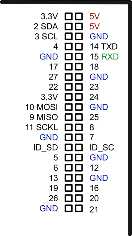
If you have a Raspberry Pi, it is most likely to be a model B rev. 2 board, as shown in Figure B-2.
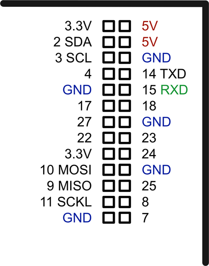
The very first released version of the Raspberry Pi model B (rev. 1) has some minor pinout differences to the rev. 2 that followed. This is the only version of the Raspberry Pi that is not compatible with later pinouts. The incompatible pins that changed are highlighted in bold in Figure B-3.
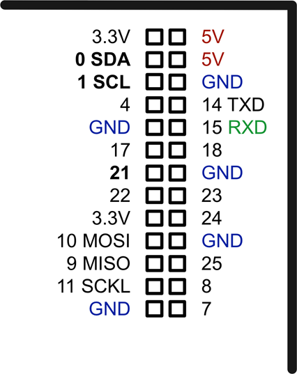
The animal on the cover of Raspberry Pi Cookbook is the Eurasian sparrowhawk (Accipiter nisus), which also goes by the names northern sparrowhawk or simply sparrowhawk. This small bird of prey is found throughout the Old World. Adult males have bluish-gray upper plumage and orange-barred underparts; females and younger birds are all brown with brown-barred underparts. The female is up to 25% larger than the male.
The sparrowhawk specializes in preying on woodland birds, but can be found in any habitat hunting garden birds in towns or cities. Males favor hunting smaller birds—tits, finches, and sparrows; females tend to catch thrushes and starlings, and are capable of killing birds weighing up to 18 ounces (500 grams) or more.
Eurasian sparrowhawks breed in nests that can measure up to 60 cm (2 feet) across, built with twigs. Afterward, four or five pale blue, brown-spotted eggs are laid. Success of breeding relies on females maintaining a high weight; the male delivers food to its mate. After 33 days, the chicks hatch, and they fledge after 24 to 28 days.
A juvenile sparrowhawk has a 34% chance of surviving its first year. After that, its chance of survival more than doubles, with 69% of adults surviving from one year to the next. The typical lifespan of these birds is four years. Mortality is greater for young males than for young females. Despite a sharp population decline after WWII, the sparrowhawk is the most common bird of prey in Europe. The use of organochlorine insecticides to treat seeds before sowing has been known to incapacitate or kill sparrowhawks. Those affected lay fragile-shelled eggs that break during incubation. After the chemicals were banned, the sparrowhawk population recovered and remains common, classified as Least Concern by BirdLife International.
The cover image is from Cassell’s Natural History. The cover fonts are URW Typewriter and Guardian Sans. The text font is Adobe Minion Pro; the heading font is Adobe Myriad Condensed; and the code font is Dalton Maag’s Ubuntu Mono.
Second Edition
Copyright © 2016 Simon Monk. All rights reserved.
Printed in the United States of America.
Published by O’Reilly Media, Inc., 1005 Gravenstein Highway North, Sebastopol, CA 95472.
O’Reilly books may be purchased for educational, business, or sales promotional use. Online editions are also available for most titles (http://safaribooksonline.com). For more information, contact our corporate/institutional sales department: 800-998-9938 or corporate@oreilly.com.
See http://oreilly.com/catalog/errata.csp?isbn=9781491939109 for release details.
The O’Reilly logo is a registered trademark of O’Reilly Media, Inc. Raspberry Pi Cookbook, the cover image, and related trade dress are trademarks of O’Reilly Media, Inc.
While the publisher and the author have used good faith efforts to ensure that the information and instructions contained in this work are accurate, the publisher and the author disclaim all responsibility for errors or omissions, including without limitation responsibility for damages resulting from the use of or reliance on this work. Use of the information and instructions contained in this work is at your own risk. If any code samples or other technology this work contains or describes is subject to open source licenses or the intellectual property rights of others, it is your responsibility to ensure that your use thereof complies with such licenses and/or rights.
978-1-491-93910-9
[LSI]
Launched in 2011, the Raspberry Pi has found a role both as a very low-cost Linux-based computer and as a platform for embedded computing. It has proven popular with educators and hobbyists alike.
Since the first edition of this book, several million more Raspberry Pis have been sold and a number of new models of Raspberry Pi have been produced. Some models—like the models B+, A+, and Pi 2 model B+—improve the specification of this device, culminating in the Raspberry Pi 2 with quad-core processor and the Raspberry Pi Compute model, which provide the Raspberry Pi as a plugin board that can become part of a larger system.
This edition has been thoroughly updated to encompass the new models of Raspberry Pi, as well as the many changes and improvements to its Raspbian operating system.
This edition contains a new chapter on computer vision and a chapter of recipes on making Internet of Things projects with your Raspberry Pi.
This book is designed in such a way that you can read it linearly as you would a regular book, or access recipes at random. You can search the table of contents or index for the recipe that you want and then jump right to it. If the recipe requires you to know about other things, it will refer you to other recipes, rather like a cookbook might refer you to base sauces before showing you how to cook something fancier.
The world of Raspberry Pi moves quickly. With a large, active community, new interface boards and software libraries are being developed all the time. In addition to examples that use specific interface boards or software, the book also covers basic principles so that you can have a better understanding of how to use new technologies that come along as the Raspberry Pi ecosystem develops.
As you would expect, a large body of code (mostly Python programs) accompanies the book. These programs are all open source and available on GitHub. You’ll find a link to them at the Raspberry Pi Cookbook website.
For most of the software-based recipes, all you need is a Raspberry Pi. I recommend a Raspberry Pi 2 or 3. When it comes to recipes that involve making your own hardware to interface with the Raspberry Pi, I have tried to make good use of ready-made modules, as well as solderless breadboard and jumper wires to avoid the need for soldering.
For those wishing to make breadboard-based projects more durable, I suggest using prototyping boards with the same layout as a half-sized breadboard, such as those sold by Adafruit, so that the design can easily be transferred to a soldered solution.
The following typographical conventions are used in this book:
Indicates new terms, URLs, email addresses, filenames, and file extensions.
Constant widthUsed for program listings, as well as within paragraphs to refer to program elements such as variable or function names, databases, data types, environment variables, statements, and keywords.
Constant width boldShows commands or other text that should be typed literally by the user.
Constant width italicShows text that should be replaced with user-supplied values or by values determined by context.
This icon signifies a tip, suggestion, or general note.
This icon indicates a warning or caution.
This icon points you to the related video for that section.
Supplemental material (code examples, exercises, etc.) is available for download at http://www.raspberrypicookbook.com.
This book is here to help you get your job done. In general, if example code is offered with this book, you may use it in your programs and documentation. You do not need to contact us for permission unless you’re reproducing a significant portion of the code. For example, writing a program that uses several chunks of code from this book does not require permission. Selling or distributing a CD-ROM of examples from O’Reilly books does require permission. Answering a question by citing this book and quoting example code does not require permission. Incorporating a significant amount of example code from this book into your product’s documentation does require permission.
We appreciate, but do not require, attribution. An attribution usually includes the title, author, publisher, and ISBN. For example: “Raspberry Pi Cookbook, Second Edition, by Simon Monk (O’Reilly). Copyright 2016 Simon Monk, 978-1-491-93910-9.”
If you feel your use of code examples falls outside fair use or the permission given above, feel free to contact us at permissions@oreilly.com.
Safari Books Online is an on-demand digital library that delivers expert content in both book and video form from the world’s leading authors in technology and business.
Technology professionals, software developers, web designers, and business and creative professionals use Safari Books Online as their primary resource for research, problem solving, learning, and certification training.
Safari Books Online offers a range of plans and pricing for enterprise, government, education, and individuals.
Members have access to thousands of books, training videos, and prepublication manuscripts in one fully searchable database from publishers like O’Reilly Media, Prentice Hall Professional, Addison-Wesley Professional, Microsoft Press, Sams, Que, Peachpit Press, Focal Press, Cisco Press, John Wiley & Sons, Syngress, Morgan Kaufmann, IBM Redbooks, Packt, Adobe Press, FT Press, Apress, Manning, New Riders, McGraw-Hill, Jones & Bartlett, Course Technology, and hundreds more. For more information about Safari Books Online, please visit us online.
Please address comments and questions concerning this book to the publisher:
We have a web page for this book, where we list errata, examples, and any additional information. You can access this page at http://bit.ly/rasp-pi-ckbk_2e.
To comment or ask technical questions about this book, send email to bookquestions@oreilly.com.
For more information about our books, courses, conferences, and news, see our website at http://www.oreilly.com.
Find us on Facebook: http://facebook.com/oreilly
Follow us on Twitter: http://twitter.com/oreillymedia
Watch us on YouTube: http://www.youtube.com/oreillymedia
As always, I thank my wife Linda for her patience and support.
I also thank the technical reviewer Duncan Amos for his keen eye, good humor, and excellent suggestions that have without a doubt contributed greatly to this book.
Thanks also to all the O’Reilly team, especially those I met at the Cambridge office, who were very welcoming when I visited, and of course Nan Reinhardt for her diligent copyediting.
When you buy a Raspberry Pi, you are essentially buying an assembled printed circuit board. It does not even include a power supply or operating system.
The recipes in this chapter are concerned with getting your Raspberry Pi set up and ready for use.
Because the Raspberry Pi just uses standard USB keyboards and mice, most of the setup is pretty straightforward, so you will concentrate only on those tasks that are specific to the Raspberry Pi.
If you want a Raspberry Pi for general use, then you should buy a Raspberry Pi 3 or 2 model B. With four times as much memory and a quad-core processor, it will cope with most tasks much better than the Pi Zero or model A+ with their single processors. The Raspberry Pi 3 model B has the great advantage of having WiFi built in, so there’s no need for an extra USB WiFi adapter.
If, on the other hand, you are embedding a Raspberry Pi in a project for a single purpose, then using a model A+ or Pi Zero and saving a few dollars may well be an option.
Figure 1-1 shows the Pi Zero, model A+, and Raspberry Pi 2 B.
As you can see from Figure 1-1, the model A+ is smaller than the Pi 2 and has a single USB socket and no RJ45 Ethernet socket. The Pi Zero is even smaller, saving space by using a mini HDMI socket and micro USB on-the-go socket. If you want to connect a keyboard monitor and mouse to a Pi Zero, you will need adapters for both the USB and HDMI ports before you can connect standard peripherals.
The differences between all the Raspberry Pi models to date are summarized in Table 1-1.
| Model | RAM | USB sockets | Ethernet port | Notes |
|---|---|---|---|---|
| 3 B | 1 GB | 4 | yes | Includes WiFi |
| Zero | 512 MB | 1 (micro) | no | Low cost |
| 2 B | 1 GB | 4 | yes | Quad-core |
| A+ | 256 MB | 1 | no | |
| B+ | 512 MB | 4 | yes | Discontinued |
|
A |
256 MB |
1 |
no |
Discontinued |
|
B rev2 |
512 MB |
2 |
yes |
Discontinued |
|
B rev1 |
256 MB |
2 |
yes |
Discontinued |
If you have one of the older discontinued Raspberry Pi models, it is still useful. They do not have quite the performance of the latest Raspberry Pi 3 model B, but for many situations, that does not matter.
In Recipe 9.21, the Raspberry Pi Compute module will be introduced. This is designed specifically to allow a Raspberry Pi to be built into a product.
For more information on the Raspberry Pi models, see http://en.wikipedia.org/wiki/Raspberry_Pi.
The low cost of the Pi Zero makes it ideal for embedding in electronics projects without worrying about the cost. See Recipe 9.22.
The Raspberry Pi does not come with an enclosure unless you buy one as part of a kit. This makes it a little vulnerable, as there are bare connections on the underside of the circuit board that could easily be short-circuited if the Raspberry Pi is placed on something metal.
It is a good idea to buy some protection for your Raspberry Pi in the form of a case. If you intend to use the Raspberry Pi’s GPIO pins, then the PiBow Coupé shown in Figure 1-2 is a beautiful and practical design.
There is a vast array of case styles to choose from, including:
Simple, two-part, click-together plastic boxes
VESA mountable boxes (for attaching to the back of a monitor or TV)
Lego-style boxes
3D-printed box designs
Laser-cut, snap-together acrylic designs
The case you buy is very much a matter of personal taste. However, some of the things you need to consider are:
Do you need to have access to the GPIO connector? This is important if you plan to attach external electronics to your Raspberry Pi.
Is the case well-ventilated? This is important if you plan to overclock your Raspberry Pi (Recipe 1.10) or run it hard playing videos or games, as these will all generate more heat.
You will also find heatsink kits that have tiny self-adhesive heatsinks to attach to the chips on the Raspberry Pi. These may be of some use if you are demanding a lot of your Raspberry Pi, say by playing a lot of videos, but generally they are the equivalent of “go-faster” stripes on a car.
Adafruit has a nice range of Raspberry Pi enclosures.
You will also find many styles of cases at other Raspberry Pi suppliers and on eBay.
The basic electrical specification for a power supply suitable for a Raspberry Pi is that it supplies a regulated 5V DC (direct current).
The amount of current that the power supply must be capable of providing depends both on the model of Raspberry Pi and the peripherals attached to it. It is worth getting a power supply that can easily cope with the Raspberry Pi and you should consider 700mA to be a minimum.
If you buy your power supply from the same place that you buy the Raspberry Pi, then the seller should be able to tell you if it will work with the Raspberry Pi.
If you are going to be using a WiFi dongle or other USB peripherals that use significant amounts of power, then I would get a power supply capable of 1.5A or even 2A. Also beware of very low-cost power supplies that may not provide an accurate or reliable 5V.
The power supply and connector are actually the same as those found in many smartphone chargers. If they are terminated in a micro USB plug, then they are almost certainly 5V (but check). The only question, then, is if they can supply enough current.
If they can’t, then a few bad things can happen:
They may get hot and be a potential fire risk.
They may just fail.
At times of high load (say, when the Pi is using a WiFi dongle), the voltage may dip and the Raspberry Pi may reset itself.
In general, look for a power supply that says it can supply 700mA or more. If it specifies a number of watts (W) rather than mA, divide the number of watts by 5 to get the mA figure. So, a 5V 10W power supply can supply 2A (2000mA).
Using a power supply with, say, a maximum current of 2A will not use any more electricity than a 700mA power supply. The Raspberry Pi will just take as much current as it needs.
In Figure 1-3, I measure the current taken by a Raspberry Pi model B and compare it with a Raspberry Pi 2 model B.
The newer Raspberry Pis (the A+, B+, or Raspberry Pi 2) are far more power-efficient than the older models, but when the processor is fully occupied and has a lot of peripherals attached, they can still reach similar current requirements.
In Figure 1-3, you can see that the current rarely gets above 500mA. However, the processor isn’t really doing very much here. Were you to start playing HD video, the current would increase considerably. When it comes to power supplies, it’s usually better to have something in reserve.
You can buy a module that will turn off the power when the Raspberry Pi shuts down at http://www.pi-supply.com/.
The answer to this question depends on what you intend to do with your Raspberry Pi.
For general use as a computer or for using in electronic projects, you should use Raspbian, the standard and official distribution for the Raspberry Pi.
If you plan to use your Raspberry Pi as a media center, there are a number of distributions specifically for that purpose (see Recipe 4.1).
In this book, we use the Raspbian distribution almost exclusively, although most of the recipes will work with any Debian-based distribution.
MicroSD cards are not expensive, so get a few and try out a few distributions. If you do this, it is a good idea to keep your own files on a USB flash drive so that you don’t have to keep copying them onto each microSD card.
Note that if you are using one of the upcoming recipes to write your own SD card, then you need to have a computer that has an SD card slot (many laptops do), or you can buy an inexpensive USB SD card reader.
NOOBS is by far the easiest way to get an operating system onto your Raspberry Pi.
Download the NOOBS archive file from http://www.raspberrypi.org/downloads, extract it, and place it on a microSD card. To do this, you will need a computer with an SD card slot or a USB adapter and a SD-to-microSD adapter.
Once you have downloaded the NOOBS archive file, extract it and copy the folder contents onto the SD card. Note that if the archive extracts to a folder called NOOBS_v1_3_12 or similar, it is the contents of the folder that should be copied to the root of the microSD card, not the folder itself.
Put the microSD card containing the extracted NOOBS files into your Raspberry Pi and then power up your Raspberry Pi. When it boots, the window shown in Figure 1-4 will appear. From this screen, select Raspbian and then click the Install button.
If you are using NOOBS on an A+, you will see a shorter list of options because only the distributions for that simplified platform will be shown.
You will get a warning message that the SD card will be overwritten (which is fine) and then as the distribution is installed onto the SD card, you will see a progress screen accompanied by helpful information about the distribution (Figure 1-5).
Once the file copying is complete, you will get the message Image applied successfully. When you hit return, the Raspberry Pi will reboot and then raspi_config will automatically run so that you can configure the new installation.
Once you are up and running, the first thing you should do is connect your Raspberry Pi to the Internet (Recipes 2.1 and 2.5), open a command line by using LXTerminal (Recipe 3.2), and enter the following command to update your system to the latest version.
$ sudo apt-get update $ sudo apt-get upgrade
This will take some time.
For NOOBS to install correctly onto a microSD card, the card must be formatted as FAT32. Most SD and microSD cards are supplied already formatted in FAT32. If you are reusing an old card and need to format it as FAT32, then use your operating system’s tool for formatting removable media.
The type of microSD card that you get will also affect how fast your Raspberry Pi runs once the operating system is installed. Look for a microSD card described as “class 10.”
You can find further information on installing an operating system with NOOBS, including information about the different distributions available at https://www.raspberrypi.org/help/noobs-setup/.
Unless you are embedding your Raspberry Pi in a project or using it as a media center, you need to attach a keyboard, mouse, monitor, and probably a WiFi dongle, unless you have a Raspberry Pi 3.
Figure 1-6 shows a typical Raspberry Pi system.
The Raspberry Pi is perfectly happy with pretty much any keyboard or mouse, wired or wireless. The exception to this is Bluetooth wireless keyboards and mice, which will not work with the Raspberry Pi.
If you have an older Raspberry Pi or a model A or A+ and run out of USB sockets, then you will also need a USB hub.
Many people have been caught out by this problem. Fortunately, it is possible to buy adapters for monitors with a DVI or VGA input but no HDMI connectors.
DVI adapters are the simplest and cheapest. They can be found for less than $5 if you search for “HDMI male to DVI female converter.”
Using VGA adapters is more complex because they require some electronics to convert the signal from digital to analog, so beware of leads that do not contain these. The official converter is called Pi-View and is available wherever the Raspberry Pi is sold. Pi-View has the advantage of having been tested and found to work with Raspberry Pi. You may find cheaper alternatives on the Internet, but often these won’t work.
eLinux has tips on what to look for in an converter.
The Raspberry Pi has two types of video output: HDMI and composite video from the audio jack, for which you need a special cord. Of these, the HDMI is much better quality. If you’re intending to use a composite video as your main screen, you may want to think again.
If you are using such a screen—say, because you need a really small screen—then you need to make a few adjustments to fit the video output to the screen. You need to make some changes to the file /boot/config.txt. You can edit it on the Raspberry Pi by issuing the following command in a Terminal session:
$ sudo nano /boot/config.txt
If the text is too small to read and you do not have an HDMI monitor, then you can also edit the file by removing the SD card from the Raspberry Pi and inserting it into your computer. The file will then be in the top-level directory on the SD card, so you can use a text editor on your PC to modify it.
You need to know the resolution of your screen. For a lot of small screens, this will be 320 by 240 pixels. Find the two lines in the file that read:
#framebuffer_width=1280 #framebuffer_height=720
Remove the # from the front of each line and change the two numbers to the width and height of your screen. In the following example, these lines have been modified to be 320 by 240:
framebuffer_width=320 framebuffer_height=240
Save the file and restart your Raspberry Pi. You should find that everything has become a lot easier to read. You will probably also find that there is a big, thick border around the screen. To adjust this, see Recipe 1.9.
There are many low-cost CCTV monitors that can make a great companion for the Raspberry Pi when you’re making something like a retro games console (Recipe 4.6). However, these monitors are often very low resolution.
For another tutorial on using composite monitors, see this Adafruit tutorial.
Also, see Recipes 1.7 and 1.9 to adjust your picture when you’re using the HDMI video output.
If your text extends off the screen, use the raspi-config tool to turn overscan off.
To do this, run raspi-config by opening a Terminal session and issuing the command:
$ sudo raspi-config
Then use the cursor keys to scroll down to Advanced Options and then Overscan, and turn overscan off (Figure 1-7).
If your problem is that there is a large black border around the picture, then you can reduce this (and possibly eliminate it entirely) by editing the file /boot/config.txt using the command:
$ sudo nano /boot/config.txt
Look for the section dealing with overscan. The four lines you need to change are shown in the middle of Figure 1-8.
For the lines to take effect, you first need to uncomment them by removing the # character from the start of each line.
Then, using trial and error, change the settings until the screen fills as much of the monitor as possible. Note that the four numbers should be negative. Try setting them all to –20 to start with. This will increase the area of the screen that is used.
Having to repeatedly restart the Raspberry Pi to see the effects of the changes in resolution is a little tedious. Fortunately, you will only have to do this procedure once. Many monitors and TVs work just fine without any adjustments.
You can find much more information about the raspi-config tool at http://elinux.org/RPi_raspi-config.
If you have a Raspberry Pi 2 with its quad-core processor, you are unlikely to find it to be too slow. However, the older single-core Raspberry Pis can be pretty sluggish.
You can increase the clock frequency of a Raspberry Pi to make it run a little faster. This will make it use a bit more power and run a little hotter (see the Discussion next).
The method of overclocking described here is called dynamic overclocking because it automatically monitors the temperature of the Raspberry Pi and drops the clock speed back down if things start to get too hot.
To make your Pi overclock, run the raspi_config utility by issuing the following command in a Terminal:
$ sudo raspi-config
Select the Overclock option in the menu, and you are presented with the options in Figure 1-9.
Select an option. If you find that your Raspberry Pi starts to become unstable and hangs unexpectedly, then you may need to choose a more conservative option or turn overclocking off by setting it back to None.
The performance improvements from overclocking can be quite dramatic. To measure these, I used a Raspberry Pi model B, revision 2, without a case at an ambient room temperature of 15 degrees C.
The test program was the following Python script. This just hammers the processor and is not really representative of the other things that go on in a computer, such as writing to the SD card, graphics, and so on. But it does give a good indication of raw CPU performance if you want to test the effect of overclocking on your Raspberry Pi.
importtimedeffactorial(n):ifn==0:return1else:returnn*factorial(n-1)before_time=time.clock()foriinrange(1,10000):factorial(200)after_time=time.clock()(after_time-before_time)
Check out the results of the test in Table 1-2.
| Speed test | Current | Temperature (degrees C) | |
|---|---|---|---|
| 700 MHz | 15.8 seconds | 360mA | 27 |
| 1 GHz | 10.5 seconds | 420mA | 30 |
As you can see, the performance has increased by 33% but at a cost of drawing more current and a slightly higher temperature.
A well-ventilated enclosure will help to keep your Raspberry Pi running at full speed. There have also been some efforts to add water-cooling to the Raspberry Pi. Frankly, this is just silly.
You can find much more information about the raspi-config tool at http://elinux.org/RPi_raspi-config.
You can use the raspi-config tool to change your password. Run the raspi_config utility by issuing the following command in a Terminal (see Recipe 3.2):
$ sudo raspi-config
Then select the change_pass option in the menu and follow the prompts shown in Figure 1-10.
Changing your password is one occasion where you do not have to restart your Raspberry Pi for the changes to take effect.
You can also change the password from a Terminal session simply by using the passwd command as follows:
$ passwd Changing password for pi. (current) UNIX password: Enter new UNIX password: Retype new UNIX password: passwd: password updated successfully
You can find much more information about the raspi-config tool at http://elinux.org/RPi_raspi-config.
You can use the raspi-config tool to change the boot behavior so that the Raspberry Pi automatically logs you in and starts the desktop. Run the raspi_config utility by issuing the following command in a Terminal:
$ sudo raspi-config
Then select the Enable Boot to Desktop/Scratch option and then “Desktop Log in as user pi”(Figure 1-11).
After you change the boot option, you are prompted to restart your Raspberry Pi for the changes to take effect.
You can find much more information about the raspi-config tool at http://elinux.org/RPi_raspi-config.
Click on the Raspberry menu in the top-left corner of the desktop. This will display a number of options (Figure 1-12).
Shuts down the Raspberry Pi. You will need to unplug the power and plug it in again to get the Raspberry Pi to boot up again.
Reboots the Raspberry Pi.
Logs you out and displays a prompt to enter your login credentials so that you can log back in.
You can also reboot from the command line by issuing the command:
sudo reboot
You may have to do this after installing some software. When you do reboot, you see the message shown in Figure 1-13, which illustrates the multiuser nature of Linux and warns all users connected to the Pi.
It is better to shut your Raspberry Pi down as described above than to simply pull out the power plug, because the Raspberry Pi may be in the middle of writing to the microSD card as you power it down. This could lead to file corruption.
Unlike shutting down most computers, shutting down a Raspberry Pi does not actually turn off the power. It goes into a low-power mode—and it is a pretty low-power device anyway (but the Raspberry Pi hardware has no control over its power supply).
You can buy a module that will turn off the power when the Raspberry Pi shuts down at http://www.pi-supply.com/.
You want to use the Raspberry Pi camera module (see Figure 1-14).
The Raspberry Pi camera module (Figure 1-14) is attached to a Raspberry Pi by a ribbon cable.
This cable attaches to a special connector between the audio and HDMI sockets on a Raspberry Pi 2. On an original Raspberry Pi model B, the connector is just behind the Ethernet socket. To fit it, pull up the levers on either side of the connector so that they unlock, and then press the cable into the slot with the connector pads of the cable facing away from the Ethernet socket. Press the two levers of the connector back down to lock the cable in place (Figure 1-15).
The camera module packaging states that it is sensitive to static. Before handling it, ground yourself by touching something grounded like the metal case of a PC.
The camera module requires some software configuration. The easiest way to configure it is to use raspi_config. To run raspi-config, enter the following command into a Terminal session:
$ sudo raspi-config
You will see the Enable Camera option (Figure 1-16).
Two commands are available for capturing still images and videos: raspiStill and raspivid.
To capture a single still image, use the raspiStill command as shown here:
$ raspistill -o image1.jpg
A preview screen displays for about five seconds and then takes a photograph and stores it in the file image1.jpg in the current directory.
To capture video, use the command raspivid:
$ raspivid -o video.h264 -t 10000
The number on the end is the recording duration in milliseconds—in this case, 10 seconds.
Both raspstill and raspivid have a large number of options. If you type either command without any parameters, help text displays options that are available.
The camera module is capable of high-resolution stills and video recording.
Here are some of the key features of the camera:
5-megapixel sensor
Fixed focus f/2 lens
Still resolution 1920×1080
Video 1080p, 30fps
An alternative to the camera module is to use a USB webcam (see Recipe 8.2).
The RaspiCam documentation includes raspstill and raspivid.
Attach a USB Bluetooth adapter to the Raspberry Pi and install the supporting Bluetooth software.
Not all Bluetooth adapters are compatible with the Raspberry Pi. Most are, but to be sure, buy one that is advertised as working with the Raspberry Pi. Figure 1-17 shows a Raspberry Pi 2 equipped with both a USB Bluetooth adapter (nearest to the camera) and a USB WiFi adapter.
To install the software needed to support Bluetooth, enter the following commands:
$ sudo apt-get update $ sudo apt-get install bluetooth bluez-utils blueman bluez $ sudo usermod -G bluetooth -a pi
These commands should work for all Bluetooth adapters supported by the Raspberry Pi.
Plug your Bluetooth adapter in and then reboot your Raspberry Pi (Recipe 1.13).
You will now find a new entry on the Raspbian Start menu under the Preferences section called Bluetooth Manager. Open this utility and click Search to look for nearby Bluetooth devices (Figure 1-18). Make sure that there are some Bluetooth devices set to be discoverable.
From the Bluetooth Manager, you can pair with other Bluetooth devices, send them files, and configure the visibility of your Raspberry Pi to other Bluetooth devices.
For a list of Bluetooth adapters that are compatible with the Raspberry Pi, see http://elinux.org/RPi_USB_Bluetooth_adapters.
The Raspberry Pi is designed to be connected to the Internet. Its ability to communicate on the Internet is one of its key features and opens up all sorts of possible uses, including home automation, web serving, network monitoring, and so on.
The connection can be wired through an Ethernet cable (at least in the case of the model B), or the Pi can use a USB WiFi module to provide a network connection.
Having a connected Raspberry Pi also means that you can connect to it remotely from another computer. This is very useful in situations where the Raspberry Pi itself is inaccessible and does not have a keyboard, mouse, and monitor attached to it.
This chapter gives you recipes for connecting your Raspberry Pi to the Internet and controlling it remotely over a network.
First, if you have a Raspberry Pi model A, A+, or Zero, there is no RJ45 connector for Ethernet. In this case, your best option for Internet access is to use a wireless USB adaptor (see Recipe 2.5).
If you have a Raspberry Pi model B, plug an Ethernet patch cable into its RJ45 socket and then connect the other end to a spare socket on the back of your home router. Figure 2-1 shows an original Raspberry Pi 1 where the Network LEDs are next to the audio socket. On a Raspberry Pi 2, the LEDs are built into the Ethernet socket itself.
The network LEDs on your Raspberry Pi should immediately start to flicker as the Raspberry Pi connects to your network.
Raspbian is preconfigured to connect to any network using Dynamic Host Configuration Protocol (DHCP). It will automatically be assigned an IP address as long as DHCP is enabled on your network.
If the network LEDs on your Raspberry Pi do not light up when you plug it into the home router, check that you have not used the Uplink RJ45 socket on the hub or try a different cable.
If the LEDs blink but you cannot connect to the Internet on your Raspberry Pi using a browser, check that DHCP is enabled on your network management console. Look for an option like that shown in Figure 2-2.
To connect to a wireless network, see Recipe 2.5.
You want to know the IP address of your Raspberry Pi so that you can communicate with it, whether connecting to it as a web server, exchanging files, or controlling it remotely with SSH (Recipe 2.7) or VNC (Recipe 2.8).
An IP address is a four-part number uniquely identifying a computer’s network interface within a network. Each part is separated by a dot.
To find the IP address of your Raspberry Pi, you need to issue this command in a Terminal window:
$ hostname -I 192.168.1.16
This is the local IP address of your Raspberry Pi on your home network.
A Raspberry Pi can have more than one IP address (i.e., one for each network connection). So if you have both a wired connection and a wireless connection to your Pi, it would have two IP addresses. Normally, however, you would only connect it by one method or the other, not both. To see all the network connections, use the ifconfig command:
$ sudo ifconfig eth0 Link encap:Ethernet HWaddr b8:27:eb:d5:f4:8f inet addr:192.168.1.16 Bcast:192.168.255.255 Mask:255.255.0.0 UP BROADCAST RUNNING MULTICAST MTU:1500 Metric:1 RX packets:1114 errors:0 dropped:1 overruns:0 frame:0 TX packets:1173 errors:0 dropped:0 overruns:0 carrier:0 collisions:0 txqueuelen:1000 RX bytes:76957 (75.1 KiB) TX bytes:479753 (468.5 KiB) lo Link encap:Local Loopback inet addr:127.0.0.1 Mask:255.0.0.0 UP LOOPBACK RUNNING MTU:16436 Metric:1 RX packets:0 errors:0 dropped:0 overruns:0 frame:0 TX packets:0 errors:0 dropped:0 overruns:0 carrier:0 collisions:0 txqueuelen:0 RX bytes:0 (0.0 B) TX bytes:0 (0.0 B) wlan0 Link encap:Ethernet HWaddr 00:0f:53:a0:04:57 inet addr:192.168.1.13 Bcast:192.168.255.255 Mask:255.255.0.0 UP BROADCAST RUNNING MULTICAST MTU:1500 Metric:1 RX packets:38 errors:0 dropped:0 overruns:0 frame:0 TX packets:28 errors:0 dropped:0 overruns:0 carrier:0 collisions:0 txqueuelen:1000 RX bytes:6661 (6.5 KiB) TX bytes:6377 (6.2 KiB)
Looking at the results of running this ifconfig, you can see that the Pi in question is connected by both a wired connection (eth0) with an IP address of 192.168.1.16, and a wireless one (wlan0) with an IP address of 192.168.1.13. The lo network interface is a virtual interface that allows the computer to communicate with itself.
Another way to find your IP address is to connect to the management console of your home hub and find the LAN page and then the IP table. There should be a device listed called raspberrypi with its IP address next to it.
Wikipedia has everything you want to know about IP addresses.
To set the IP address of your Raspberry Pi, whether using a wired or wireless network, you need to edit the configuration file /etc/network/interfaces.
If you view your /etc/network/interfaces file using the following command:
$ more /etc/network/interfaces
it should look something like this:
auto lo iface lo inet loopback iface eth0 inet dhcp allow-hotplug wlan0 iface wlan0 inet manual wpa-roam /etc/wpa_supplicant/wpa_supplicant.conf iface default inet dhcp
This is telling you that Raspbian is aware of three network interfaces on your Raspberry Pi, each starting with the word iface.
loLoopback. You can ignore this.
eth0A network connection using the Ethernet socket.
wlan0A network interface using a USB WiFi adapter or the built-in WiFi hardware of the Raspberry Pi 3.
Your Raspberry Pi will have a different IP address for each network connection. In this example, you will just make the IP address for the Ethernet interface static. If you want to do the same for the WiFi interface, just edit that entry in the interfaces file instead.
To edit this file, type the following command:
$ sudo nano /etc/network/interfaces
First, decide on an IP address to use. You need to pick one that is both unused by any other machine on the network and within the allowed range of IP addresses for your home hub. In this case, I will use 192.168.1.116.
Modify the contents of the file, changing the word dhcp to static and adding the following lines:
address 192.168.1.116
netmask 255.255.255.0
gateway 192.168.1.1
With the file changed as shown here, the static IP address of 192.168.1.116 has been assigned to the eth0 interface.
auto lo iface lo inet loopback iface eth0 inet static address 192.168.1.116 netmask 255.255.255.0 gateway 192.168.1.1 allow-hotplug wlan0 iface wlan0 inet manual wpa-roam /etc/wpa_supplicant/wpa_supplicant.conf iface default inet dhcp
For most networks, the netmask setting should be set to 255.255.255.0 and the gateway should be the IP address of your home router itself. This will be the same as the IP address you use to connect to the admin console of your router.
After you edit and save the file, run the following commands to clear out all the existing DHCP leases, and restart your Pi so that the changes will take effect.
$ sudo rm /var/lib/dhcp/* $ sudo reboot
Internal IP addresses are typically something like 192.168.1.116, where just the last number is changed for each of the different computers. Another common format for internal IP addresses is 10.0.0.16.
Wikipedia has everything you want to know about IP addresses.
Changing the name of your Pi is pretty straightforward. There are just two files that need to be changed.
First, edit the file /etc/hostname. You can do this by opening a Terminal window and typing the command:
$ sudo nano /etc/hostname
Replace “raspberrypi” with a name of your choice. This should remain one word, without any punctuation or unusual characters (including the _ character.)
Second, open the file /etc/hosts in an editor using the command:
$ sudo nano /etc/hosts
The file will look something like this:
127.0.0.1 localhost ::1 localhost ip6-localhost ip6-loopback fe00::0 ip6-localnet ff00::0 ip6-mcastprefix ff02::1 ip6-allnodes ff02::2 ip6-allrouters 127.0.1.1 raspberrypi
Change the text at the end that uses the old name (“raspberrypi”) to the new name.
Restart the Pi, and you should find that the name has changed when you view it on the network from another computer.
Changing the name of your Pi can be very useful, especially if you have more than one Pi connected to your network.
See also Recipe 2.3 to change the IP address of your Raspberry Pi.
If you have the latest version of Raspbian, then setting up WiFi is really easy. Just plug in a USB WiFi adapter and then click on the Network icon at the top right of your screen (Figure 2-3). You will then be presented with a list of WiFi networks. Select your network and you will be prompted to enter your Pre Shared Key (password). Enter your password, and after a while, the Network Icon will switch to show the standard WiFi symbol and you will be connected.
If you have an older distribution of Raspbian, you will have to use the WiFi Config utility with a shortcut on the desktop. If you are not using a recent distribution, then you should update to one anyway (see Recipe 1.4).
If you have a Raspberry Pi 3, then the the board already has WiFi hardware built-in. If you have an older Raspberry Pi, plug a compatible USB wireless adapter (most are compatable) into one of the USB sockets on your Raspberry Pi, and launch the WiFi Config utility (Figure 2-4). You will find the WiFi Configuration tool under the Preferences section of the Raspberry start menu. Then click the Scan button to search for access points. Double-click on the access point (for your home hub) that you want to join and then enter the password in the PSK field.
Finally, click Connect to join the network.
USB WiFi adapters can use quite a lot of power, so if you find your Pi rebooting unexpectedly or not booting properly, then you may need to use a larger power supply for it. Look for a supply that is 1.5A or more.
If you’re using a keyboard and mouse as well, you may find you’ve run out of USB sockets. In that case, a USB hub is the answer. Choosing a hub with its own power supply will also help with the power problem.
If you are using your Raspberry Pi as a media center (see Recipe 4.1), then there will be a settings page to allow you to connect the media center to your network using WiFi.
You can also set up a wireless connection by using just the command line. To do so, first edit the file /etc/network/interfaces by using the command:
$ sudo nano /etc/network/interfaces
Then find the section of the file relating to the wlan0 interface and change it to be:
allow-hotplug wlan0 iface wlan0 inet dhcp wpa-roam /etc/wpa_supplicant/wpa_supplicant.conf
The first line specifies that the WiFi connection should automatically start when a USB WiFi dongle is inserted. The second specifies that the Raspberry Pi should allocate the IP address using DHCP. If you want to use a static IP address, replace the word dhcp with static and add in the extra lines described in Recipe 2.3 to allocate a static IP address.
The final line specifies the location of a supplicant file. This is the file that actually contains the SSID (network name) and PSK (password) for your wireless network. So, next you will edit this file using the command:
$ sudo nano /etc/wpa_supplicant/wpa_supplicant.conf
Modify the file, setting the values of ssid and pskfoobar for your wireless network.
ctrl_interface=DIR=/var/run/wpa_supplicant GROUP=netdev
update_config=1
network={
ssid="My-Network-Name"
psk="My-password"
proto=RSN
key_mgmt=WPA-PSK
pairwise=TKIP
auth_alg=OPEN
}
For the changes to the file to take effect, reboot your Raspberry Pi.
For wired connections, see also Recipe 2.1. For a list of WiFi adapters that are compatible with the Raspberry Pi, go to http://elinux.org/RPi_VerifiedPeripherals.
For more information on setting up a wired network, see Recipe 2.1.
Use a console cable to connect to a Raspberry Pi.
Console cables are great for a Pi that is going to be used headless—that is, without keyboard, mouse, or monitor. The console cable shown in Figure 2-5 is available from Adafruit.
Connect the lead as follows:
Connect the red (5V) lead to the 5V pin one pin to the left of the edge of the GPIO header.
Connect the black (GND) lead to GND on the next pin to the left on the Raspberry Pi.
Connect the white lead (RX) to Raspberry Pi GPIO 14 (TXD) to the left of the black lead.
Connect the green lead (RX) to 15 (RXD) to the left of the white lead on the Raspberry Pi.
If you use a different lead, the wire colors may well be different, so always check the documentation for the lead else or you may damage your Raspberry Pi.
Note that the USB lead also provides 5V on the red wire, with enough power for the Pi on its own but not with a lot of devices attached.
If you are a Windows or Mac OS X user, you will need to install drivers for the USB lead, which are available for Windows and for Mac OS X. Linux users usually don’t need to install any drivers for these leads.
To connect to the Pi from Mac OS X, you will need to run the Terminal and enter the command:
$ sudo cu -l /dev/cu.NoZAP-PL2303-00001004 -s 115200
The exact device name will be different, but if you press Tab after cu.P, it will autocomplete. After connecting, press Enter, and the Raspberry Pi login prompt should appear (Figure 2-6). The default username and password are pi and raspberry, respectively.
If you are trying to connect to your Raspberry Pi from a Windows computer, you need to download the terminal software called Putty.
When you run Putty, change the “Connection type” to Serial and set the speed to 115200. You also need to set the “Serial line” to be the COM port in use by the cable. This may be COM7, but if that does not work, check into using the Windows Device manager.
When you click Open and press Enter, the Terminal session should start with a login prompt.
The console cable can be a very convenient way of using your Pi if you are traveling light, as it provides both power and a way to control the Pi remotely.
The console lead has a chip in the USB end that provides a USB-to-serial interface. This sometimes (depending on your operating system) requires the installation of drivers on your PC. The lead used here is one supplied by Adafruit (product code 954). You should be able to use any USB-to-serial converter as long as it has the necessary drivers for your PC.
Plugging the sockets of the lead into the right places is made easier if you carefully glue the four sockets together in the right order so that they fit over the GPIO header in a block.
Finding the right position on the GPIO header is made easier if you use a GPIO template like the Raspberry Leaf (see Recipe 9.1).
You can find out more about using the serial console at this Adafruit tutorial. Adafruit also sells console cables.
Before you can connect to your Raspberry Pi using SSH, you must enable SSH. On newer versions of Raspbian, you can use the Raspberry Pi Configuration tool (Figure 2-7) that you will find on the main menu under Preferences. Just check the box for SSH and click OK. You will be prompted to restart.
If you have an older version of Raspbian, use the raspi_config application. Start this at any time by entering the following command in Terminal:
$ sudo raspi-config
Scroll down to the SSH option and enable it.
On newer versions of Raspbian, SSH is automatically enabled and there is no setting to change.
If you are using Mac OS X or have Linux installed on the computer from which you want to connect your Pi, then all you need to do to connect is open a Terminal window and enter the command:
$ ssh 192.168.1.16 -l pi
where the IP address (192.168.1.16) is the IP address of your Pi (see Recipe 2.2). You will be prompted for your password and then logged in to the Pi (Figure 2-8).
To connect from a Windows computer, you will need to use Putty (Recipe 2.6) to start an SSH session.
SSH is a very common way of connecting to remote computers; any commands that you could issue on the Pi itself, you can use from the secure shell. It is also, as the name suggests, secure because the communication is encrypted.
Perhaps the only drawback is that it is a command-line rather than graphical environment. If you need access to the full Raspberry Pi desktop environment remotely, then you need to use VNC (Recipe 2.8) or RDP (Recipe 2.9).
See also this Adafruit tutorial.
Install a Virtual Network Connection (VNC) server.
Open a Terminal session (or SSH session) on the Pi and run the following commands:
$ sudo apt-get update $ sudo apt-get install tightvncserver
Having installed the VNC server, run it using the command:
$ vncserver :1
The first time you run this, you will be prompted to create a new password so that anyone connecting remotely has to enter the password before being granted access to the Pi.
To connect to the Pi from a remote computer, you need to install a VNC client. RealVNC is a popular choice and connects well with tightvnc and is available for Windows, Linux, and Mac OS X.
When you run the client program on Mac OS X or a PC, you will be asked to enter the IP address of the VNC server you want to connect to (the IP address of your Pi). Enter “:1” after the IP address to indicate that you wish to connect to display number 1.
You will then be prompted for the password. Remember, this is the password you set previously after installing tightvncserver and is not necessarily the same as your normal Raspberry Pi password.
Although you can do most things with SSH, sometimes it is useful to have access to the graphical environment of the Pi.
If you want the VNC server to automatically start whenever you restart your Raspberry Pi, follow these steps:
$ cd /home/pi $ cd .config $ mkdir autostart $ cd autostart $ nano tightvnc.desktop
Paste the following into the editor window:
[Desktop Entry] Type=Application Name=TightVNC Exec=vncserver :1 StartupNotify=false
As long as your Raspberry Pi is set to automatically log in and boot into the windowing environment, the VNC server will automatically start when you reboot.
Install the XRDP software on your Raspberry Pi by entering the following commands:
$ sudo apt-get update $ sudo apt-get install xrdp
Once the software is installed, it will automatically start the xrdp service, which means the service will automatically start when the Raspberry Pi is rebooted.
If you have Windows 7 or later, then it already includes an RPD client for connecting to your Raspberry Pi. You will find it on your Start menu under All Programs/Accessories/Remote Desktop Connection. For older versions of Windows, you can download the client from: ModMyPi.
Mac OS X users can download the Microsoft RDP client for OS X from Microsoft’s website.
A client for Linux machines is available from http://www.rdesktop.org/.
When you start your RDP client, you will be prompted for the computer you want to connect to. Enter the IP address of your Raspberry Pi. You will then be prompted for the username and password (Figure 2-10), which are the same as your usual Raspberry Pi login—that is, a username of pi and a password of raspberry unless you have changed it.
RDP does the same job as VNC but works more efficiently and therefore refreshes the contents of the screen more smoothly. The only downside is that for Mac OS X users, it does not integrate with the Share Screen feature of OS X.
See also Recipe 2.8.
The Mac OS X operating system includes built-in support for file viewing in Finder over the network (Figure 2-11). However, you must make some configuration changes on your Raspberry Pi for OS X to pick these up.
You will need to know the IP address of your Raspberry Pi (Recipe 2.2).
Now, on the Raspberry Pi, install netatalk by using the command:
$ sudo apt-get install netatalk
Then, back on your Mac, in the Finder menu, select Go→Connect to Server and enter afp://192.168.1.16 as the server address (but use the IP address for your Raspberry Pi instead of the one shown here). Then click Connect. You will be prompted to log in. I had to reboot my Raspberry Pi before I got the login prompt.
Log in using the name pi and your password, which will be raspberry by default. The Finder should then show you the contents of your home directory on the Raspberry Pi.
There are a few more configuration changes to make on the Raspberry Pi.
$ sudo apt-get install avahi-daemon $ sudo update-rc.d avahi-daemon defaults
Next, type the command:
$ sudo nano /etc/avahi/services/afpd.service
Paste the following code into the file:
<?xml version="1.0" standalone='no'?><!--*-nxml-*-->
<!DOCTYPE service-group SYSTEM "avahi-service.dtd">
<service-group>
<name replace-wildcards="yes">%h</name>
<service>
<type>_afpovertcp._tcp</type>
<port>548</port>
</service>
</service-group>
To set the daemon running, type the command:
$ sudo /etc/init.d/avahi-daemon restart
Switch back to your Mac, and you should now see your Raspberry Pi in the Finder.
Being able to move files easily between your Mac and your Raspberry Pi is very useful. It means that you can use files on your Pi without having to hook up a separate keyboard, mouse, and monitor.
You can also open files on the Raspberry Pi as if they were on your Mac. This has the advantage that you can edit them with TextMate or your favorite OS X text editor.
If you’re using Windows or Linux, you can also share files by configuring your Raspberry Pi to work as Network Attached Storage (NAS); see Recipe 2.12.
The instructions here were adapted from this tutorial, which credits Matt Richardson and Shawn Wallace’s book Getting Started with Raspberry Pi (O’Reilly) as the original source.
First, follow Recipe 2.8 to install VNC. You will also need to complete Recipe 2.10.
Then enter the command:
$ sudo nano /etc/avahi/services/rfb.service
and paste the following into the editor:
<?xml version="1.0" standalone='no'?>
<!DOCTYPE service-group SYSTEM "avahi-service.dtd">
<service-group>
<name replace-wildcards="yes">%h</name>
<service>
<type>_rfb._tcp</type>
<port>5901</port>
</service>
</service-group>
Now enter the command:
$ sudo /etc/init.d/avahi-daemon restart
You should now be able to see the Share Screen option shown in Figure 2-12. When prompted for a password, use the password you set up for VNC, not your general Raspberry Pi password.
This recipe just adds a little convenience to the process of sharing the screen of your Raspberry Pi.
If you have more than one Raspberry Pi on your network, you need to give them different names so that you can identify them on the network (Recipe 2.4).
If you are a Windows or Linux user, you can still connect to a Raspberry Pi using VNC (Recipe 2.8).
The instructions here were adapted from this tutorial, which credits Matt Richardson and Shawn Wallace’s book Getting Started with Raspberry Pi (O’Reilly) as the original source.
The solution to this problem is to install and configure Samba. To do this, issue the commands:
$ sudo apt-get install samba $ sudo apt-get install samba-common-bin
Now, attach the USB hard drive to the Raspberry Pi. It will automatically mount in your /media folder. To check that it’s there, use the command:
$ cd /media $ ls
The drive should be listed with whatever name you gave it when you formatted it. It will automatically mount itself whenever the Raspberry Pi reboots.
You now need to configure Samba so the drive can be shared on the network. To do this, you first need to add a Samba user (pi). Enter the following command and type in a password:
$ sudo smbpasswd -a pi New SMB password: Retype new SMB password: Added user pi.
You now need to make some changes to the file /etc/samba/smb.conf, so enter the command:
$ sudo nano /etc/samba/smb.conf
The first line you’re looking for is near the top of the file:
workgroup = WORKGROUP
You only need to change this if you plan to connect from a Windows machine. This should be the name of your Windows workgroup. For Windows XP, the default is MSHOME; for newer versions of Windows, it is HOME. (But check on your Windows network.)
The next change to be made is further down the file in the Authentication section. Find the line:
# security = user
Remove the # from the front to turn security on.
Finally, scroll right to the end of the file and add the following lines:
[USB] path = /media/NAS comment = NAS Drive valid users = pi writeable = yes browseable = yes create mask = 0777 public = yes
Save the file and then restart Samba by entering the command:
$ sudo /etc/init.d/samba restart
If all is well, your USB drive should now be shared on your network.
To connect to the drive on a Mac OS X, just select Go→Connect to Server from the Finder menu. Then enter smb://raspberrypi/USB in the Server Address field. You will see a login dialog box, where you need to change the username to pi (Figure 2-13).
If you are connecting to the NAS from a Windows machine, the exact procedure will vary depending on your version of Windows. However, the basic principle is that at some point you will need to enter the network address, which should be \\raspberrypi\USB (Figure 2-14).
You will then be prompted for the username and password before you can use the NAS disk (Figure 2-15).
If you are a Linux user, this command should mount the NAS drive for you:
$ sudo mkdir /pishare $ sudo smbmount -o username=pi,password=raspberry //192.168.1.16/USB /pishare
You may wish to change your Raspberry Pi’s network name to something inappropriate like piNAS (see Recipe 2.4).
Use Common Unix Printing System (CUPS).
Start by entering the following command into a Terminal to install CUPS. This may take some time.
$ sudo apt-get install cups
Give yourself admin privileges for CUPS by entering the following command:
$ sudo usermod -a -G lpadmin pi
CUPS is configured via a web interface. Neither the Midori or Dillo web browsers work very well with the CUPS administration pages, but Iceweasel works just fine. You can install the Iceweasel browser by entering the following command:
$ sudo apt-get install iceweasel
Start Iceweasel from the Internet group of your Start menu and navigate to the address http://localhost:631.
Go to the Administration tab and choose the Add Printer option. This will display a list of printers that are on the network or connected directly to the Raspberry Pi’s USB port (Figure 2-16).
Follow the series of dialog boxes to set up the printer.
When you’re finished, you can test out the printer by firing up AbiWord (see Recipe 4.2). Type some text, and when you’re ready to print it, you should see your newly added printer available for printing (Figure 2-17).
See also the official CUPS website.
Use the File Manager.
You can find this program on your Start menu in the Accessories group (Figure 3-1).
Using the File Manager, you can drag a file or directory from one directory to another or use the Edit menu to copy a file from one location and paste it to a second. This operates in much the same way as the Windows File Manager or Mac OS X Finder.
The lefthand side of the File Manager shows the volumes that are mounted, so if you connect a USB flash drive or external USB drive, it will appear here.
The central area displays the files in the current folder, which you can navigate using the buttons in the toolbar or by typing a location in the file path area at the top.
Right-click a file to reveal options that can be used on that file (Figure 3-2).
See also Recipe 3.4.
Select the LX Terminal icon (looks like a black computer monitor) at the top of the Raspberry Pi Desktop, or select the Terminal menu option on the Start menu in the Accessories group (Figure 3-3).
When the LX Terminal starts, it is set to your home directory (/home/pi).
You can open as many Terminal sessions as you want. It is often useful to have a couple of sessions open in different directories so that you don’t have to constantly switch directories using cd (Recipe 3.3).
In the next section (Recipe 3.3), you will look at navigating the directory structure using the Terminal.
The main command used for navigating the filesystem is cd (change directory). After cd, you have to specify the directory that you want to change to. This can either be a relative path to a directory inside your current directory, or an absolute path to somewhere else on the filesystem.
To see what the current directory is, you can use the command pwd (print working directory).
Try out a few examples. Open a Terminal session, and you should see a prompt like this:
pi@raspberrypi ~ $
The prompt that you will see after each command (pi@raspberrypi ~ $) is a reminder of your username (pi) and your computer name (raspberrypi). The ~ character is shorthand for your home directory (/home/pi). So, at any point, you can change your current directory to your home directory as follows:
$ cd ~
Throughout the book, I use a $ at the start of each line where you are expected to type a command. The response from the command line will not be prefixed by anything; it will appear just as it does on the Raspberry Pi’s screen.
You can confirm that the command did indeed set the directory to the home directory by using the pwd command:
$ pwd /home/pi
If you want to move up one level in the directory structure, you can use the special value .. (two dots) after the cd command, as shown here:
$ cd .. $ pwd /home
As you may have deduced by now, the path to a particular file or directory is made up of words separated by a /. So the very root of the whole filesystem is /, and to access the home directory within / you would refer to /home/. Then, to find the pi directory within that, you would use /home/pi/. The final / can be omitted from a path.
Paths can also be absolute (starting with a / and specifying the full path from the root), or they can be relative to the current working directory, in which case they must not start with a /.
You will have full read and write access to the files in your home directory, but once you move into the places where system files and applications are kept, your access to some files will be restricted to read only. You can override this (Recipe 3.11), but some care is required.
Check out the root of the directory structure by entering the following commands:
$ cd / $ ls bin dev home lost+found mnt proc run selinux sys usr boot etc lib media opt root sbin srv tmp var
The ls command (list) shows us all the files and directories underneath / the root directory. You will see that there is a home directory listed, which is the directory you have just come from.
Now change into one of those directories by using the command:
$ cd etc $ ls adduser.conf hosts.deny polkit-1 alternatives hp profile apm iceweasel profile.d apparmor.d idmapd.conf protocols apt ifplugd pulse asound.conf init python
You will notice a couple of things. First, there are a lot of files and folders listed, more than can fit on the screen at once. Use the scroll bar on the side of the Terminal window to move up and down.
Second, you will see that the files and folders have some color-coding. Files are displayed in white, whereas directories are blue.
Unless you particularly like typing, the Tab key offers a convenient shortcut. If you start typing the name of a file, pressing the Tab key allows the autocomplete feature to attempt to complete the filename. For example, if you’re going to change directory to network, type the command cd netw and then press the Tab key. Because netw is enough to uniquely identify the file or directory, pressing the Tab key will autocomplete it.
If what you have typed is not enough to uniquely identify the file or directory name, then pressing the Tab key another time will display a list of possible options that match what you have typed so far. So, if you had stopped at net and pressed the Tab key, you would see the following:
$ cd net netatalk/ network/
You can provide an extra argument after ls to narrow down the things you want to list. Change directory to /etc and then run the following:
$ ls f* fake-hwclock.data fb.modes fstab fuse.conf fonts: conf.avail conf.d fonts.conf fonts.dtd foomatic: defaultspooler direct filter.conf fstab.d: pi@raspberrypi /etc $
The * character is called a wildcard. In specifying f* after ls, we are saying that we want to list everything that starts with an f.
Helpfully, the results first list all the files within /etc that start with f, and then the contents of all the directories in that folder starting with f.
A common use of wildcards is to list all files with a certain extension (e.g., ls *.docx).
A convention in Linux (and many other operating systems) is to prefix files that should be hidden from the user by starting their name with a period. Any so-named files or folders will not appear when you type ls unless you also supply ls with the option -a. For example:
$ cd ~ $ ls -a . Desktop .pulse .. .dillo .pulse-cookie Adafruit-Raspberry-Pi-Python-Code .dmrc python_games .advance .emulationstation sales_log .AppleDB .fltk servo.py .AppleDesktop .fontconfig .stella .AppleDouble .gstreamer-0.10 stepper.py.save Asteroids.zip .gvfs switches.txt.save atari_roms indiecity Temporary Items .bash_history .local thermometer.py .bash_logout motor.py .thumbnails .bashrc .mozilla .vnc .cache mydocument.doc .Xauthority .config Network Trash Folder .xsession-errors .dbus .profile .xsession-errors.old
As you can see, most of the files and folders in your home directory are hidden.
See also Recipe 3.13.
Use the cp command to copy files and directories.
You can, of course, copy files by using the File Manager and its copy and paste menu options (Recipe 3.1).
The simplest example of copying in a Terminal session is to make a copy of a file within your working directory. The cp command is followed first by the file to copy, and then by the name to be given to the new file.
For example, the following example creates a file called myfile.txt and then makes a copy of it with the name myfile2.txt. You can find out more about the trick of creating a file using the > command in Recipe 3.8.
$ echo "hello" > myfile.txt $ ls myfile.txt $ cp myfile.txt myfile2.txt $ ls myfile.txt myfile2.txt
Although in this example, both file paths are local to the current working directory, the file paths can be to anywhere in the filesystem where you have write access. The following example copies the original file to an area /tmp, which is a location for temporary files. Do not put anything important in that folder.
$ cp myfile.txt /tmp
Note that in this case, the name to be given to the new file is not specified, just the directory where it is to go. This will create a copy of myfile.txt in /tmp with the same name of myfile.tmp.
Sometimes, rather than copying just one file, you may want to copy a whole directory full of files and possibly other directories. To copy such a directory, you need to use the -r option (for recursive). This will copy the directory and all its contents.
$ cp -r mydirectory mydirectory2
Whenever you are copying files or folders, if you do not have permission, the result of the command will tell you that. You will need to either change the permissions of the folder into which you are copying (Recipe 3.13) or copy the files with superuser privileges (Recipe 3.11).
The mv (move) command is used in a similar way to the cp command, except that the file or folder being moved is simply renamed rather than a duplicate being made.
For example, to simply rename a file from my_file.txt to my_file.rtf, you use the command:
$ mv my_file.txt my_file.rtf
Changing a directory name is just as straightforward, and you don’t need the recursive -r option you used when copying because changing a directory’s name implicitly means that everything within it is contained in a renamed directory.
Use the editor nano included with most Raspberry Pi distributions.
To use nano, simply type the command nano followed by the name or path to the file that you want to edit. If the file does not exist, it will be created when you save it from the editor. However, this will only happen if you have write permissions in the directory where you are trying to write the file.
From your home directory, type the command nano my_file.txt to edit or create the file nano my_file.txt. Figure 3-4 shows nano in action.
You cannot use the mouse to position the cursor; use the arrow keys instead.
The area at the bottom of the screen lists a number of commands that you access by holding down the Ctrl key and pressing the letter indicated. Most of these are not that useful. The ones that you are likely to use most of the time are:
Exit. You will be prompted to save the file before nano exits.
Next page. Think of it as an arrow pointing downward. This allows you to move through a large file one screen at a time.
Previous page.
Where is. This allows you to search for a piece of text.
There are also some fairly crude cut-and-paste type options there, but in practice, it’s easier to use the normal clipboard from the menu that you access with a right-click.
Using this clipboard also allows you to copy and paste text between other windows such as your browser.
When you’re ready to save your changes to the file and exit nano, use the command Ctrl-X. Type Y to confirm that you want to save the file. nano then displays the filename as the default name to save the file under. Press Enter to save and exit.
If you want to abandon changes you have made, enter N in place of Y.
Editors are very much a matter of personal taste. Many other editors that are available for Linux will work just fine on Raspberry Pi. The vim (vi improved) editor has many fans in the Linux world. This is also included in the popular Raspberry Pi distributions. It is not, however, an easy editor for the beginner. You can run it in the same way as nano, but using the command vi instead of nano. There are more details on using vim at http://newbiedoc.sourceforge.net/text_editing/vim.html.en.
The cat command displays the whole contents of the file, even if it is longer than will fit on the screen.
The more command just displays one screen of text at a time. Press the space bar to display the next screen.
You can also use cat to concatenate (join together) a number of files (Recipe 3.30).
Another popular command related to more is less. less is like more except it allows you to move backward in the file as well as forward.
This can be useful for quickly creating a file.
To use the more command to view files without using an editor, see Recipe 3.7.
To use > to capture other kinds of system output, see Recipe 3.29.
To create a directory, use the mkdir command. Try out the following example:
$ cd ~ $ mkdir my_directory $ cd my_directory $ ls
You need to have write permission in the directory within which you are trying to create the new directory.
For general information on using the Terminal to navigate the filesystem, see Recipe 3.3.
The rm (remove) command will delete a file or directory and its contents. It should be used with extreme caution.
Deleting a single file is simple and safe. The following example will delete the file my_file.txt from the home directory:
$ cd ~ $ rm my_file.txt $ ls
You need to have write permission in the directory within which you are trying to carry out the deletion.
You can also use the * wildcard when deleting files. This example will delete all the files starting with my_file. in the current directory:
$ rm my_file.*
You could also delete all the files in the directory by typing:
$ rm *
If you want to recursively delete a directory and all its contents, including any directories that it contains, you can use the -r option:
$ rm -r mydir
When deleting files from a Terminal window, remember that you do not have the safety net of a recycle bin from which files can be undeleted. Also, generally speaking, you won’t be given the option to confirm; the files will just be immediately deleted. This can be totally devastating if you combine it with the command sudo (Recipe 3.11).
See also Recipe 3.3.
If you are concerned about accidentally deleting files or folders, you can force the rm command to confirm by setting up a command alias (Recipe 3.34).
The sudo (substitute user do) command allows you to perform actions with superuser privileges. Just prefix the command with sudo.
Most tasks that you want to perform on the command line can usually be performed without superuser privileges. The most common exceptions to this are when you’re installing new software and editing configuration files.
For example, if you try to use the command apt-get update, you will receive a number of permission denied messages:
$ apt-get update E: Could not open lock file /var/lib/apt/lists/lock - open (13: Permission denied) E: Unable to lock directory /var/lib/apt/lists/ E: Could not open lock file /var/lib/dpkg/lock - open (13: Permission denied) E: Unable to lock the administration directory (/var/lib/dpkg/), are you root?
The message at the end—are you root?—gives the game away. If you issue the same command prefixed with sudo, the command will work just fine:
$ sudo apt-get update Get:1 http://mirrordirector.raspbian.org wheezy InRelease [12.5 kB] Hit http://archive.raspberrypi.org wheezy InRelease Get:2 http://mirrordirector.raspbian.org wheezy/main Sources [6,241 kB] Hit http://archive.raspberrypi.org wheezy/main armhf Packages Ign http://archive.raspberrypi.org wheezy/main Translation-en_GB Ign http://archive.raspberrypi.org wheezy/main Translation-en 40% [2 Sources 2,504 kB/6,241 kB 40%]
If you have a whole load of commands to run as superuser and don’t want to have to prefix each command with sudo, you can use the following command:
$ sudo sh #
Note how the prompt changes from $ to #. All subsequent commands will be run as superuser. When you want to revert to being a regular user, enter the command:
# exit $
To understand more about file permissions, see Recipe 3.12.
To install software using apt-get, see Recipe 3.16.
Run the command ls -l, and you will see a result like this:
$ ls -l total 16 -rw-r--r-- 1 pi pi 5 Apr 23 15:23 file1.txt -rw-r--r-- 1 pi pi 5 Apr 23 15:23 file2.txt -rw-r--r-- 1 pi pi 5 Apr 23 15:23 file3.txt drwxr-xr-x 2 pi pi 4096 Apr 23 15:23 mydir
Figure 3-6 shows the different sections of the listing information. The first section contains the permissions. In the second column, the number 1 (labeled “Files”) indicates how many files are involved. This field only makes sense if the listing entry is for a directory; if it is a file, it will mostly be just 1. The next two entries (both pi) are the owner and group of the file. The size entry (the fifth column) indicates the size of the file in bytes. The modified date will change every time the file is edited or changed and the final entry is the actual name of the file or directory.
The permissions string is split into four sections (Type, Owner, Group, and Other). The first section is the type of the file. If this is a directory, it will be the character d; if it is just a file, the entry will be just a -.
The next section of three characters specifies the owner permissions for that file. Each character is a flag that is either on or off. So if the owner has read permissions, there will be a r in the first character position. If he has write permissions, there will be a w in the second slot. The third position, which is - in this example, can be x if the file is executable (a program or script) for the owner.
The third section has the same three flags but for any users in the group. Users can be organized into groups. So, in this case, the file has a user pi and a group ownership of pi. If there were any other users in the group pi, they would have the permissions specified here.
The final section specifies the permissions for any other users who are neither pi nor in the group pi.
Since most people will only ever use the Raspberry Pi as the user pi, the permissions of most interest are in the first section.
To change file permissions, see Recipe 3.13.
Common reasons why you might want to change file permissions include needing to edit a file that is marked as read-only and giving a file execute permissions so that it can run as a program or script.
The chmod command allows you to add or remove permissions for a file. There are two syntaxes for doing this; one requires the use of octal (base 8) and the other is text-based. You will use the easier-to-understand text method.
The first parameter to chmod is the change to make, and the second is the file or folder to which it should apply. This change parameter takes the form of the permission scope (+, -, = for add, remove, and set, respectively) and then the permission type.
For example, the following code will add execute (x) rights to the file for the owner of the file file2.txt.
$ chmod u+x file2.txt
If we now list the directory, we can see that the x permission has been added.
$ ls -l total 16 -rw-r--r-- 1 pi pi 5 Apr 23 15:23 file1.txt -rwxr--r-- 1 pi pi 5 Apr 24 08:08 file2.txt -rw-r--r-- 1 pi pi 5 Apr 23 15:23 file3.txt drwxr-xr-x 2 pi pi 4096 Apr 23 15:23 mydir
If we wanted to add execute permission for the group or other users, then we could use g and o, respectively. The letter a will add the permission to everyone.
For background on file permissions, see Recipe 3.12.
See Recipe 3.14 for changing file ownership.
As we discovered in Recipe 3.12, any file or directory has both an owner and a group associated with it. Since most users of the Raspberry Pi will just have the single user of pi, we don’t really need to worry about groups.
Occasionally, you will find files on your system that have been installed with a different user than pi. If this is the case, you can change the ownership of the file by using the chown command.
To just change the owner of a file, use chown followed by the new owner and group, separated by a colon, and then the name of the file.
You will probably find that you need superuser privileges to change ownership, in which case, prefix the command with sudo (Recipe 3.11).
$ sudo chown root:root file2.txt $ ls -l total 16 -rw-r--r-- 1 pi pi 5 Apr 23 15:23 file1.txt -rwxr--r-- 1 root root 5 Apr 24 08:08 file2.txt -rw-r--r-- 1 pi pi 5 Apr 23 15:23 file3.txt drwxr-xr-x 2 pi pi 4096 Apr 23 15:23 mydir
For background on file permissions, see Recipe 3.12.
Also see Recipe 3.13 for changing file permissions.
Install and use the delightfully named scrot screen capture software.
To install scrot, run the following command from Terminal:
$ sudo apt-get install scrot
The simplest way to trigger a screen capture is to just enter the command scrot. This will immediately take an image of the primary display and save it in a file named something like 2013-04-25-080116_1024x768_scrot.png within the current directory.
Sometimes you want a screenshot to show a menu being opened or something that generally disappears when the window in which you are interested loses focus. For such situations, you can specify a delay before the capture takes place using the -d option.
$ scrot -d 5
The delay is specified in seconds.
If you capture the whole screen, you can crop it later with image editing software, such as Gimp (Recipe 4.11). However, it is more convenient to just capture an area of the screen in the first place, which you can do using the -s option.
To use this option, type this command and then drag out the area of screen that you want to capture with the mouse.
$ scrot -s
The filename will include the dimensions in pixels of the image captured.
The scrot command has a number of other options to control things like using multiple screens and changing the format of the saved file. You can find out more about scrot from its manpage by entering the following command.
$ man scrot
For more information on installing with apt-get, see Recipe 3.16.
The most frequently used tool for installing software from a Terminal session is apt-get.
The basic format of the command, which you must run as a superuser, is:
$ sudo apt-get install <name of software>
For example, to install the AbiWord word processing software, you would enter the command:
$ sudo apt-get install abiword
The apt-get package manager uses a list of available software. This list is included with the Raspberry Pi operating system distribution that you use but is likely to be out-of-date. So if the software that you try to install is reported by apt-get as not found, run the following command to update the list:
$ sudo apt-get update
The list and the software packages for installation are all on the Internet, so none of this will work unless your Raspberry Pi has an Internet connection.
If you find that when you update, you get an error like E: Problem with MergeList /var/lib/dpkg/status, try running these commands:
sudo rm /var/lib/dpkg/status sudo touch /var/lib/dpkg/status
The installation process can often take a while because the files have to be downloaded and installed. Some installations will also add shortcuts to your desktop, or the program groups on your Start menu.
You can search for software to install using the command apt-get search followed by a search string such as abiword. This will then display a list of matching packages that you could install.
See Recipe 3.17 for removing programs that you no longer need so that you can free up space.
See also Recipe 3.20 for downloading source code from GitHub.
The apt-get utility has an option (remove) that will remove a package, but it will only remove packages that have been installed with apt-get install.
For example, if you wanted to remove AbiWord, you would use the command:
$ sudo apt-get remove abiword
Removing a package like this does not always delete everything, as packages often also have prerequisite packages that are installed as well. To remove these, you can use the autoremove option, as shown here:
$ sudo apt-get autoremove abiword $ sudo apt-get clean
The apt-get clean option will do some further tidying up of unused package installation files.
See Recipe 3.16 for installing packages using apt-get.
If you have the latest version of Raspbian, then pip will already be installed and you can run pip from the command line as shown in the example here, which is taken from Recipe 8.1 where it is used to install the Python library svgwrite.
$ sudo pip install svgwrite
If pip is not installed on your system, then you can install it by using the commands:
$ sudo apt-get install python-pip
Although many Python libraries can be installed using apt-get (see Recipe 3.16), some cannot and you must use pip.
To install software using apt-get, see Recipe 3.16.
Use the wget command to fetch a file from the Internet.
For example:
$ wget http://www.icrobotics.co.uk/wiki/images/c/c3/Pifm.tar.gz --2013-06-07 07:35:01-- http://www.icrobotics.co.uk/wiki/images/c/c3/Pifm.tar.gz Resolving www.icrobotics.co.uk (www.icrobotics.co.uk)... 155.198.3.147 Connecting to www.icrobotics.co.uk (www.icrobotics.co.uk)|155.198.3.147| :80... connected. HTTP request sent, awaiting response... 200 OK Length: 5521400 (5.3M) [application/x-gzip] Saving to: `Pifm.tar.gz' 100%[==================================================>] 5,521,400 601K/s 2013-06-07 07:35:11 (601 KB/s) - `Pifm.tar.gz' saved [5521400/5521400]
If your URL contains any special characters, it is a good idea to enclose it in double quotes. This example URL is from Recipe 4.10.
You will find instructions for installing software that rely on using wget to fetch files. It is often more convenient to do this from the command line rather than use a browser, find the file, download it, and then copy it to the place you need it.
The wget command takes the URL to download as its argument and downloads it into the current directory. It’s typically used to download an archive file of some type but will also download any web page.
For more information on installing with apt-get, see Recipe 3.16.
For information on selecting and using a browser, see Recipe 4.3.
To use code in Git repositories, you need to use the git clone command to fetch the files.
For example, the following command will fetch all the source code examples from this book:
$ git clone https://github.com/simonmonk/raspberrypi_cookbook_ed2.git
Modify your rc.local file to run the program you want.
Edit the file /etc/rc.local by using the command:
$ sudo nano /etc/rc.local
Add the following line after the first block of comment lines that begin with #:
$ /usr/bin/python /home/pi/my_program.py &
It is important to include the & on the end of the command line so that it is run in the background; otherwise, your Raspberry Pi will not boot.
This way of autorunning a program needs a very careful edit of rc.local, or you may stop your Raspberry Pi from booting.
A safer way of autorunning a program is detailed in Recipe 3.22.
Debian Linux, upon which most Raspberry Pi distributions are based, uses a dependency-based mechanism for automating the running of commands at startup. This is a little tricky to use and involves creating a configuration file for the script or program that you want to run in a folder called init.d.
The following example shows you how to run a Python script in your home directory. The script could do anything, but in this case, the script runs a simple Python web server, which is described further in Recipe 7.17.
The steps involved in this are:
Create an init script.
Make the init script executable.
Tell the system about the new init script.
First, create the init script. This needs to be created in the folder /etc/init.d/. The script can be called anything, but in this example, you will call it my_server.
Create the new file by using nano with the following command:
$ sudo nano /etc/init.d/my_server
Paste the following code into the editor window and save the file:
### BEGIN INIT INFO# Provides: my_server# Required-Start: $remote_fs $syslog $network# Required-Stop: $remote_fs $syslog $network# Default-Start: 2 3 4 5# Default-Stop: 0 1 6# Short-Description: Simple Web Server# Description: Simple Web Server### END INIT INFO#! /bin/sh# /etc/init.d/my_serverexportHOMEcase"$1"in start)echo"Starting My Server"sudo /usr/bin/python /home/pi/myserver.py 2>&1&;;stop)echo"Stopping My Server"PID=`ps auxwww|grep myserver.py|head -1|awk'{print $2}'`kill-9$PID;;*)echo"Usage: /etc/init.d/my_server {start|stop}"exit1;;esacexit0
This is quite a lot of work to automate the running of a script, but most of it is boiler-plate code. To run a different script, just work your way through the script, changing the descriptions and the name of the Python file you want to run.
The next step is to make this file executable for the owner, which you do using this command:
$ sudo chmod +x /etc/init.d/my_server
Now that the program is set up as a service, you can test that everything is OK before you set it to autostart as part of the boot sequence, using the following command:
$ /etc/init.d/my_server start Starting My Server Bottle v0.11.4 server starting up (using WSGIRefServer())... Listening on http://192.168.1.16:80/ Hit Ctrl-C to quit.
Finally, if that runs OK, use the following command to make the system aware of the new service that you have defined:
$ sudo update-rc.d my_server defaults
For a simpler approach to making a program run automatically, see Recipe 3.21.
For more information on changing file and folder permissions, see Recipe 3.12.
Use the Linux crontab command.
To do this, the Raspberry Pi needs to know the time and date, and therefore needs a network connection or a real-time clock. See Recipe 12.13.
The command crontab allows you to schedule events to take place at regular intervals. This can be daily or hourly, and you can even define complicated patterns so different things happen on different days of the week. This is useful for backup tasks that you might want to run in the middle of the night.
You can edit the scheduled events by using the following command:
$ crontab -e
If the script or program that you want to run needs to be run by a superuser, then prefix all the crontab commands with sudo (Recipe 3.11).
The comment line indicates the format of a crontab line. The digits are, in order, minute, hour, day of month, month, day of week, and then the command that you want to run.
The first line that starts with a # is just a comment line to remind you of the format for a crontab line.
If there is a * in the digit position, that means every; if there is a number there instead, the script will only be run at that minute/hour/day of the month.
So, to run the script every day at 1 a.m., you would add the line shown in Figure 3-7.
Using only a single digit, you can specify ranges to run the script just on weekdays; for example:
0 1 * * 1-5 /home/pi/myscript.sh
If your script needs to be run from a particular directory, you can use a semicolon (;) to separate multiple commands as shown here:
0 1 * * * cd /home/pi; python mypythoncode.py
You can see the full documentation for crontab by entering this command:
$ man crontab
Starting with a directory specified in the command, the find command will search, and if it finds the file, display its location. For example:
$ find /home/pi -name gemgem.py /home/pi/python_games/gemgem.py
You can start the search higher up the tree, even at the root of the whole filesystem (/). This will make the search take a lot longer, and will also produce error messages. You can redirect these error messages by adding 2>/dev/null to the end of the line.
To search for the file throughout the entire filesystem, use the following command:
$ find / -name gemgem.py 2>/dev/null /home/pi/python_games/gemgem.py
You can also use wildcards with find as follows:
$ find /home/pi -name match* /home/pi/python_games/match4.wav /home/pi/python_games/match2.wav /home/pi/python_games/match1.wav /home/pi/python_games/match3.wav /home/pi/python_games/match0.wav /home/pi/python_games/match5.wav
The find command has a number of other advanced features for searching. To see the full manpage documentation for find, use this command:
$ man find
Use the up and down arrow keys to select previous commands from the command history, and the history command with grep to find older commands.
You can access the previous command you ran by pressing the up arrow key. Pressing it again will take you to the command before that, and so on. If you overshoot the command you wanted, the down arrow key will take you back in the other direction.
If you want to cancel without running the selected command, use Ctrl-C.
Over time, your command history will grow too large to find a command that you used ages ago. To find a command from way back, you can use the history command.
$ history
1 sudo nano /etc/init.d/my_server
2 sudo chmod +x /etc/init.d/my_server
3 /etc/init.d/my_server start
4 cp /media/4954-5EF7/sales_log/server.py myserver.py
5 /etc/init.d/my_server start
6 sudo apt-get update
7 sudo apt-get install bottle
8 sudo apt-get install python-bottle
This lists all your command history and is likely to have far too many entries for you to find the one you want. To remedy this, you can pipe the history command into the grep command, which will just display results matching a search string. So, for example, to find all the apt-get (Recipe 3.16) commands that you’ve issued, you can use the line:
$ history | grep apt-get
6 sudo apt-get update
7 sudo apt-get install bottle
8 sudo apt-get install python-bottle
55 history | grep apt-get
Each history item has a number next to it, so if you find the line you were looking for, you can run it using ! followed by the history number, as shown here:
$ !6 sudo apt-get update Hit http://mirrordirector.raspbian.org wheezy InRelease Hit http://mirrordirector.raspbian.org wheezy/main armhf Packages Hit http://mirrordirector.raspbian.org wheezy/contrib armhf Packages .....
To find files rather than commands, see Recipe 3.24.
Use the Task Manager utility, which you’ll find on the Start menu in the System Tools program group (Figure 3-8).
The Task Manager allows you to see at a glance how much CPU and memory are being used. You can also right-click on a process and select the option to kill it from the pop-up menu.
The graphs at the top of the window display the total CPU usage and memory. The processes are listed below that, and you can see the CPU share each is taking.
If you prefer to do this type of thing from the command line, use the Linux top command to display very similar data about processor and memory and which processes are using the most resources (Figure 3-9). You can then use the kill command to kill a process. You will need to do this as superuser.
In this case, you can see that the top process is a Python program that uses 97% of CPU. The first column shows its process ID (2447). To kill this process, enter this command:
$ kill 2447
It is quite possible to kill some vital operating system process this way, but if you do, powering off your Pi and turning it back on again will restore things to normal.
Sometimes, you may have a process running that is not immediately visible when you use top. If this is the case, you can search all the processes running by using the ps command and piping (Recipe 3.31) the results to the grep command, which will search the results and highlight items of interest.
For example, to find the process ID for our CPU-hogging Python process, we could run the following command:
$ ps -ef | grep "python" pi 2447 2397 99 07:01 pts/0 00:00:02 python speed.py pi 2456 2397 0 07:01 pts/0 00:00:00 grep --color=auto python
In this case, the process ID for the Python program speed.py is 2447. The second entry in the list is the process for the ps command itself.
A variation on the kill command is the killall command. Use this with caution, as it kills all processes that match its argument. So, for example, the following command will kill all Python programs running on the Raspberry Pi:
$ sudo killall python
See also the manpages for top, ps, grep, kill, and killall. You can view these by typing man followed by the name of the command, as shown here:
$ man top
If the file that you want to uncompress just has the extension .gz, you can unzip it using the command:
$ gunzip myfile.gz
You also often find files (called tarballs) that contain a directory that has been archived with the Linux tar utility and then compressed with gzip into a file with a name like myfile.tar.gz.
You can extract the original files and folders out of a tarball by using the tar command:
$ tar -xzf myfile.tar.gz
You can find out more about tar from the manpages, which you can access by using the command man tar.
Use the lsusb command. This will list all the devices attached to the USB ports on your Raspberry Pi:
$ lsusb Bus 001 Device 002: ID 0424:9512 Standard Microsystems Corp. Bus 001 Device 001: ID 1d6b:0002 Linux Foundation 2.0 root hub Bus 001 Device 003: ID 0424:ec00 Standard Microsystems Corp. Bus 001 Device 004: ID 15d9:0a41 Trust International B.V. MI-2540D [Optical mouse]
This command will tell you whether a device is connected or not, but it will not guarantee that it is working correctly. There may be drivers to install or configuration changes to make for the hardware.
For an example of using lsusb when attaching an external webcam, see Recipe 4.5.
Use the > command to redirect output that would otherwise appear on the command line.
For example, to copy a directory listing into a file called myfiles.txt, do the following:
$ ls > myfiles.txt $ more myfiles.txt Desktop indiecity master.zip mcpi
You can use the > command on any Linux command that produces output, even if you are running, say, a Python program.
You can also use the opposite (<) command to redirect user input, although this is not nearly as useful as >.
To use cat to join together a number of files, see Recipe 3.30.
Joining files is the real purpose of the cat command. You can supply as many filenames as you like, and they will all be written to the file you direct to. If you do not redirect the output, then it will just appear in your Terminal window. If they are big files, this might take some time!
See also Recipe 3.7, where cat is used to display the contents of a file.
Use the pipe command, which is the bar symbol (|) on your keyboard, to pipe the output of one command to another. For example:
$ ls -l *.py | grep Jun -rw-r--r-- 1 pi pi 226 Jun 7 06:49 speed.py
This example will find all the files with the extension py that also have Jun in their directory listing, indicating that they were last modified in June.
At first sight, this looks rather like output redirection using > (Recipe 3.29). The difference is that +>_ will not work where the target is another program. It will only work for redirecting to a file.
You can chain together as many programs as you like, as shown here, although this isn’t something you will do often:
$ command1 | command2 | command3
See Recipe 3.26 for an example of using grep to find a process, and Recipe 3.25 to search your command history, using a pipe and grep.
Redirect the output to /dev/null using >.
For example:
$ ls > /dev/null
This example illustrates the syntax but is otherwise pretty useless. A more common use is where you’re running a program and the developer has left a lot of trace messages in her code, which you don’t really want to see. The following example hides superfluous output from the find command (see Recipe 3.34).
$ find / -name gemgem.py 2>/dev/null /home/pi/python_games/gemgem.py
For more information about redirecting standard output, see Recipe 3.29.
Run the program or command in the background using the & command.
For example:
$ python speed.py & [1] 2528 $ ls
Rather than wait until the program has finished running, the command line displays the process ID (the second number) and immediately allows you to continue with whatever other commands you want to run. You can then use this process ID to kill the background process (Recipe 3.26).
To bring the background process back to the foreground, use the fg command:
$ fg python speed.py
This will report the command or program that is running and then wait for it to finish.
Output from the background process will still appear in the Terminal.
An alternative to putting processes in the background is to just open more than one Terminal window.
For information on managing processes, see Recipe 3.26.
Edit the file ~/.bashrc using nano (Recipe 3.6), and then move to the end of the file and add as many lines as you want, like this:
alias l='ls -a'
This creates an alias called l that, when entered, will be interpreted as the command ls -a.
Save and exit the file using Ctrl-X and Ctrl-Y, and then to update the Terminal with the new alias, type the following command:
$ source .bashrc
Many Linux users set up an alias for rm like the following, so that it confirms deletions.
$ alias rm='rm -i'
This is not a bad idea, as long as you do not forget when you use someone else’s system that doesn’t have this alias set up!
For more information about rm, see Recipe 3.10.
Use the Linux date command.
The date and time format is MMDDHHMMYYYY, where MM is the month number, DD is the day of the month, HH and MM are the hours and minutes, respectively, and YYYY is the year.
For example:
$ sudo date 010203042013 Wed Jan 2 03:04:00 UTC 2013
If the Raspberry Pi is connected to the Internet, then as it boots up it will automatically set its own time using an Internet time server.
You can also use date to display the UTC time by just entering date on its own:
$ date Wed Jan 2 03:08:14 UTC 2013
If you want your Raspberry Pi to maintain the correct time even when there is no network, then you can use a real-time clock (RTC) module (Recipe 12.13).
Use the Linux df command:
$ df -h Filesystem Size Used Avail Use% Mounted on rootfs 3.6G 1.7G 1.9G 48% / /dev/root 3.6G 1.7G 1.9G 48% / devtmpfs 180M 0 180M 0% /dev tmpfs 38M 236K 38M 1% /run tmpfs 5.0M 0 5.0M 0% /run/lock tmpfs 75M 0 75M 0% /run/shm /dev/mmcblk0p1 56M 19M 38M 34% /boot
To use your Raspberry Pi as a media center, you should definitely go for the superior performance of the Raspberry Pi 3 or 2 Model B, as video playing is very processor-intensive.
You can set up your Raspberry Pi as a media center during the NOOBS installation process (Recipe 1.5). Instead of selecting Raspbian as the distribution to install, select either OpenELEC_Pi1 if you have a Raspberry Pi 1 or OpenELEC_Pi2 if you have a Raspberry Pi 2.
OpenELEC is a distribution that optimizes your Raspberry Pi as a media center. It incudes the Kodi media center software, which is based on the XBMC open source project that was originally developed to convert Xbox game consoles into media centers. The code has since been ported to many platforms including the Raspberry Pi (Figure 4-1).
Raspberry Pi is perfectly capable of playing full HD video as well as streamed music, MP3 files, and Internet radio.
Kodi is a powerful piece of software with many features. Perhaps the simplest way to check that it is working is to put some music and/or video files onto a USB flash drive or external USB hard disk and connect it to the Raspberry Pi. You should be able to play them from Kodi.
Since the Raspberry Pi is likely to be sitting near your TV, you may find that your TV has a USB port that can provide enough current to run the Raspberry Pi. If this is the case, you won’t need a separate power supply.
A wireless keyboard and mouse are a good idea because if you buy them as a pair, they will use a single USB port for the dongle, which avoids the need for wires trailing all over the place. You can also buy mini-keyboards with built-in trackpads that are useful in this situation.
A wired network connection is generally higher performance and better than a WiFi connection, but it is not always convenient to have the Pi near an Ethernet socket. If this is the case, then you can set up XBMC to use a WiFi dongle for a network connection.
Setting up Kodi is very intuitive, and you can find full instructions on using the software at http://kodi.wiki/.
You can add an IR remote to Raspberry Pi to control XBMC.
Raspberry Pi is, after all, a Linux computer, so there are several office applications that you can install to use spreadsheets and word processor documents.
Programs for the Raspberry Pi are downloaded from the Internet, so you’ll need an Internet connection.
Before you install any new software, it is a good idea to open a Terminal and run the following command:
$ sudo apt-get update
To install the AbiWord word processor, run this command:
$ sudo apt-get install abiword
You will be asked to confirm the installation by typing Y; after a minute or so, installation will be complete. If you look on your Start menu, you will see a new section called Office, where you will find AbiWord (Figure 4-2).
AbiWord will open .doc, .docx, and other common word processing document formats.
If you need to use a spreadsheet, Gnumeric is a good choice. Install it by using the command:
$ sudo apt-get install gnumeric
If you find that the office applications run a bit too slowly, try overclocking your Raspberry Pi (Recipe 1.10) to speed things up. A Raspberry Pi 3 or 2 will also run office applications much better than an older Raspberry Pi.
There are efforts in progress to port other office software to the Raspberry Pi, such as Libre Office (a fork of Open Office). Check the Internet for the latest news on office software ports.
See Recipe 3.16 for information on using apt-get.
You can use a number of browsers on the Raspberry Pi. The Pi is not a powerful computer, and modern browsers and web pages can put quite a load on it. This means that when you use a browser on a Raspberry Pi, there is always a trade-off between features and performance.
Chromium (Figure 4-3), as the name suggests, will be familiar to users of Google Chrome. It is full-featured but noticeably slow when you try to scroll up and down a busy web page. You can install Chromium by using the following command, which will put a new link in the Internet section of your Start menu:
$ sudo apt-get install chromium-browser
Another popular alternative to Midori is Iceweasel (Figure 4-4). This browser is based on Firefox and will perform faster than Chromium because it uses the mobile version of websites (when available), which will normally be much simpler HTML. You can download and install Iceweasel by using this command:
$ sudo apt-get install iceweasel
Since browsers require a certain amount of power for many websites, you really need a Raspberry Pi 3 or 2 to avoid a frustratingly slow experience.
For more information on installing with apt-get, see Recipe 3.16.
The Pi Store (Figure 4-5) is the Raspberry Pi equivalent of Apple’s App Store or Google’s Play Store; it is a place from which you can download, install, and run all sorts of applications, both free and for sale.
You will find a shortcut on your Start menu for the Pi Store application in the Internet section.
The first time you try to download an app, you will be asked to register. After you register, the app will download and appear in the My Library tab. To run the app, just double-click it.
This is a convenient way to browse for interesting programs to use on your Raspberry Pi. More and more apps are finding their way into the store.
See the official Pi Store website.
Download the motion software. This will allow you to set up a Raspberry Pi with a USB webcam connected to it so you can connect to a web page and view the webcam.
To install the software, enter the following command in a Terminal window:
$ sudo apt-get install motion
Plug in your USB webcam and type lsusb to see if the webcam is connected:
$ lsusb Bus 001 Device 001: ID 1d6b:0002 Linux Foundation 2.0 root hub Bus 001 Device 002: ID 0424:9512 Standard Microsystems Corp. Bus 001 Device 003: ID 0424:ec00 Standard Microsystems Corp. Bus 001 Device 004: ID 3538:0059 Power Quotient International Co., Ltd Bus 001 Device 006: ID eb1a:299f eMPIA Technology, Inc.
If you can’t see an entry that obviously looks like a webcam, try disconnecting it, run the command again, and see if one of the entries vanishes from the list. In this case, the final entry in the list is for the webcam.
There are now a few configuration changes that you need to make. First, edit the file /etc/motion/motion.conf using the command:
$ sudo nano /etc/motion/motion.conf
This is quite a big configuration file. Right near the top of the file, you will find the line daemon off; change this to daemon on.
The other change is much further down the file. You need to change webcam_localhost = on to webcam_localhost = off.
There is one other file that you need to change. Enter the command:
$ sudo nano /etc/default/motion
Change start_motion_daemon=no to start_motion_daemon=yes.
To get the web service running, issue the command:
$ sudo service motion start
You should now be able to open your web browser and view the webcam. To do this, you will need to know the IP address of your Raspberry Pi (Recipe 2.2).
From another computer on the same network, open a browser and go to the URL http://192.168.1.16:8081/. You will need to change the URL to match the IP address of your Raspberry Pi, but keep the :8081 port number on the end of the URL.
If all goes well, you should see something like Figure 4-6.
The motion software is actually really powerful; there are many other settings you can tweak to change how your webcam works.
By default, the webcam will be viewable only from within your network. If you want your webcam to be visible to the whole Internet, you need to set up port forwarding on your home hub. This will require you to log in to the admin console for the hub, look for the port forwarding option, and enable it for port 8081 for the IP address of the Raspberry Pi.
You will then be able to view the webcam by using the external IP address allocated by your ISP. This is usually shown on the front page of your admin console. But beware: unless you pay your ISP for a static IP address, this IP address is likely to change every time you restart your home hub modem.
Services such as No-ip can also be used to provide dynamic DNS, so that you can register a domain name that automatically follows changes to your IP address.
There is thorough documentation on the motion website.
You can find a list of webcams compatible with the Raspberry Pi at http://elinux.org/RPi_USB_Webcams.
The Raspberry Pi has a plug-in camera module (Recipe 1.14). At the time of writing, this is not compatible with motion, but it may be by the time you read this.
To use a webcam for computer vision projects, see Chapter 8.
See Recipe 3.16 for information on using apt-get.
There are a number of emulators around for game consoles from the 1980s. One of the most popular is Stella, an emulator for the Atari 2600 (Figure 4-7).
It is worth noting that even though these games are ancient, they are still owned by someone. The ROM image files that you need to play the games on an emulator like Stella—although easy to find on the Internet—are not necessarily yours to take. So, please stick to the law.
To install Stella, simply enter the following command in a Terminal window:
$ sudo apt-get install stella
Once it’s installed, you will find a new program in Games on your Start menu. Do not run it yet—you need to obtain the ROM image for a game.
If you are outside of the US and own the actual game, you are entitled to take a copy of the ROM image for backup purposes in many, but not all, countries. You can also find ROM images for some games that have been released without any license restrictions.
Now that you have the ROM image for the game you wish to play, create a folder called roms and place the ROM image in that folder. Then start Stella.
Click the image file to start a game. By default, the cursor keys are mapped to the joystick controls and the space bar is fire. You can change a number of settings for the emulator—for example, you almost certainly want to go to Video Settings and set it to fullscreen mode.
You can also use Input Settings and the Emul Events tab to map controller buttons to your keyboard.
The emulator uses a surprisingly large amount of the Raspberry Pi’s meager resources, so you may find that you need to use a Raspberry Pi 3 or 2.
If you search the Internet, you will find that many people have taken this basic setup and added a retro USB controller, like the widely available and quite low-cost Nintendo Retrolink USB Super SNES Classic Controller, and built the Pi and a monitor into a big arcade-style housing.
There are a number of other console emulators available—at various stages of maturity, and thus reliability—on the Raspberry Pi. One to consider is Mame, which emulates a number of different game platforms.
For more information on installing with apt-get, see Recipe 3.16.
Mojang, the original developers of Minecraft, have ported it to the Raspberry Pi and Minecraft Pi is pre-installed on the latest Raspbian distribution.
To get Minecraft to fit on the Raspberry Pi, the developers made some shortcuts in the graphics code. This means that you can only play the game directly on the Raspberry Pi with the keyboard, mouse, and monitor connected directly to it. It will not work over a remote VNC connection.
The Pi edition of Minecraft is based on the mobile version of Minecraft and lacks some features, most notably Redstone.
Find out more about the Raspberry Pi port of Minecraft.
You can also run a full version of the Minecraft Server on a Raspberry Pi (Recipe 4.8), although a Raspberry Pi 3 or 2 will perform a lot better (see Recipe 1.1).
Minecraft Pi also includes a Python programming interface, and in Recipe 7.20, you will learn how to send commands to Python over an SSH connection to do automated building.
The first step is to install the Java runtime environment by using these commands:
$ sudo apt-get update $ sudo apt-get install openjdk-7-jdk
Then create a directory to contain the server code and fetch the spigot Minecraft server using the commands:
$ mkdir mcserver $ cd mcserver $ wget http://getspigot.org/spigot18/spigot_server.jar
Start the server using the command:
$ java -Xms512M -Xmx800M -jar spigot_server.jar nogui
The server will soon give you the following error message:
[15:51:26 WARN]: Failed to load eula.txt [15:51:26 INFO]: You need to agree to the EULA in order to run the server. Go to eula.txt for more info. [15:51:26 INFO]: Stopping server
This is telling you that you need to accept the terms of the license agreement by editing the file called eula.txt that the server has just created for you. So, open eula.txt using nano using the command:
$ nano eula.txt
Change the line that says eula=false to eula=true and save the file, then run, and then start the server again. This time it will take several minutes to create a world and start up the server. Don’t worry, the next time you run it, it will be a lot quicker.
Eventually, the server will start and you can test it by connecting to it from another computer running Minecraft on your network.
Start Minecraft and click on Multiplayer and then Direct Connect. Enter the IP address of your Raspberry Pi (Figure 4-9) and then click Connect.
Once you are connected, you and anyone else on your network can join the server and start playing (Figure 4-10).
You will probably want to give yourself operator status in the game by typing the command:
> op YourName
where YourName is your nickname in the game.
A Raspberry Pi 2 with its four processor cores and 1 GB of memory will run a pretty decent Minecraft server. The parameters -Xms512M and -Xmx800M set the minimum and maximum amounts of memory that Java should use for the server.
The LXTerminal or SSH window will let you know when anyone connects to the server, and you can also issue various server admin commands from here. Type help for a list of commands.
When you want to stop the server, enter the command stop.
[17:41:10 INFO]: UUID of player SimonMonk is 4e3e1a27-4e7e-4bfb-b331-a30af5bd49ec [17:41:11 INFO]: SimonMonk[/192.168.1.5:58831] logged in with entity id 382 at ([world]257.23244892748414, 67.0, 185.3728463324922) >stop [17:41:20 INFO]: Stopping the server [17:41:20 INFO]: Stopping server [17:41:20 INFO]: Saving players [17:41:20 INFO]: SimonMonk lost connection: Server closed [17:41:20 INFO]: SimonMonk left the game. [17:41:21 INFO]: Saving worlds [17:41:21 INFO]: Saving chunks for level 'world'/Overworld [17:41:24 INFO]: Saving chunks for level 'world_nether'/Nether [17:41:24 INFO]: Saving chunks for level 'world_the_end'/The End >pi@Pi2headless ~/mcserver $
To allow your friends from the wider Internet to play on your server, you will need to use your router’s admin console to set up port forwarding.
You do not need to be directly connected to the Raspberry Pi to start a Minecraft server; it will work just fine if started from SSH (Recipe 2.7).
For information on running your own Minecraft server, check out http://uk.ign.com/wikis/minecraft/Admin_and_Server_Commands.
See also the Minecraft Pi edition (Recipe 4.7).
Download and run Open Arena (Figure 4-11) from the Pi Store.
Not surprisingly, you will find Open Arena in the Games section of the Pi Store. Since the game is quite violent and bloody, it comes under a plain wrapper.
Find out more about Open Arena.
For more information on using the Pi Store, see Recipe 4.4.
Be sure to check out the accompanying video for this recipe at http://razzpisampler.oreilly.com.
You want to convert your Raspberry Pi into a high-powered FM transmitter that will send a radio signal to a normal FM radio receiver (Figure 4-12).
The clever folks at Imperial College, London, have created some C code and a Python wrapper that allow you to do just this. The download even includes the theme from Star Wars to play as a sample.
All you need is a short length of wire attached to GPIO pin 4. A female-to-male header lead will work just fine for this. In fact, it should work with the radio right next to your Pi without any kind of antenna—such is the strength of the transmission.
The first step is to install the pifm library using the following commands:
$ mkdir pifm $ cd pifm $ wget http://www.icrobotics.co.uk/wiki/images/c/c3/Pifm.tar.gz $ tar -xzf Pifm.tar.gz
Next, find yourself an FM radio receiver and tune it to 103.0 MHz. If this frequency is already occupied by some other transmission, pick another frequency and make note of it.
Now run the following command (changing the final parameter from 103.0 if you had to change frequency):
sudo ./pifm sound.wav 103.0
If all is well, you should hear the stirring tones of the Star Wars theme.
You need to know that this project may not be legal in your country. The power output is higher than that of FM transmitters used with MP3 players.
You can play other .wav files, but they must be 16-bit 44.1kHz.
The code also includes a Python library that you can use within your own Python programs. So, you could write a user interface to allow the selection and playing of tunes.
The following fragment of code illustrates the use of the Python interface:
pi@raspberrypi ~/pifm $ sudo python
Python 2.7.3 (default, Jan 13 2013, 11:20:46)
[GCC 4.6.3] on linux2
Type "help", "copyright", "credits" or "license" for more information.
>>> import PiFm
>>> PiFm.play_sound("sound.wav")
Were you to put a Raspberry Pi in your vehicle, this would be a great way of outputting sound through the vehicle’s audio system—especially if you use the features of the latest version of pifm, which allow you to stream music to the FM transmitter from various sources.
This description is based on the original post from Imperial College London. This also includes clever tricks for piping music from various sources to pifm including from a USN microphone, which opens up all sorts of opportunities.
You want to edit an image.
Download and run the GNU image manipulation program (GIMP; see Figure 4-13).
To install GIMP, open a Terminal session and type the following command:
$ sudo apt-get install gimp
Once GIMP is installed, you’ll find a new entry in your Start menu under the Graphics heading called GNU Image Manipulation Program.
Despite being very hungry for memory and processor power, GIMP is quite usable on a Raspberry Pi model B.
Find out more from the GIMP website.
GIMP has a lot of features and is a very sophisticated image editing program, so it does take a little learning. You’ll find an online manual for the software at the GIMP website, under the Documentation tab.
For more information on installing with apt-get, see Recipe 3.16.
Install the VLC media player by running the following command:
sudo apt-get install vlc
Once it’s installed, you can find VLC in the Sound & Video section of your Start menu.
Run the program and select the Open Network Stream option on the Media menu. This will open a dialog box (see Figure 4-14) where you can enter the URL of the Internet radio station that you wish to play.
You will need to plug headphones or amplified speakers into the audio socket on the Raspberry Pi.
VLC can also be run from the command line:
$ vlc http://www.a-1radio.com/listen.pls -I dummy
VLC will probably produce a series of error messages, but then play the audio just fine.
This recipe borrows heavily from this tutorial, where Jan Holst takes things a step further and adds radio-style controls to the project.
For UK readers, you can find a list of the BBC radio stream URLs online.
Although there are many languages that can be used to program the Raspberry Pi, Python is the most popular. In fact, the Pi in Raspberry Pi is inspired by the word Python.
In this chapter, you will find a host of recipes to help you get programming with Raspberry Pi.
Use both. Use Python 3 until you face a problem that is best solved by reverting to version 2.
Although the latest version of Python is Python 3 and has been for years, you will find that a lot of people stick to Python 2. In fact, in the Raspbian distribution, both versions are supplied and version 2 is just called Python, whereas version 3 is called Python 3. You even run Python 3 by using the command python3. The examples in this book are written for Python 3 unless otherwise stated. Most will run on both Python 2 and Python 3 without modification.
This reluctance on the part of the Python community to ditch the old Python 2 is largely because Python 3 introduced some changes that broke compatibility with version 2. This means that some of the huge body of third-party libraries that have been developed for Python 2 won’t work under Python 3.
My strategy is to write in Python 3 wherever possible, and revert to Python 2 when I have to because of compatibility problems.
For a good summary of the Python 2 versus Python 3 debate, see the Python wiki.
The common Raspberry Pi distributions come with the IDLE Python development tool in both the Python 2 and Python 3 versions. If you are using Raspbian, you will find shortcuts to both versions of IDLE labeled Python 2 and Python 3 in the Programming section of your Start menu (Figure 5-1).
IDLE and IDLE 3 appear to be identical; the only difference is the version of Python that they use, so open IDLE 3 (Figure 5-2).
The window that opens is labeled Python Shell. This is an interactive area where you can type Python and see the results immediately. So try typing the following into the shell next to the >>> prompt:
>>>2+24>>>
Python has evaluated the expression 2 + 2 and given us the answer of 4.
The Python Shell is fine for trying things out, but if you want to write programs, then you need to use an editor. To open a new file to edit using IDLE, select New Window from the File menu (Figure 5-3).
You can now enter your program into the editor window. Just to try things, paste the following text into the editor, save the file as count.py, and then select Run Module from the Run menu. You can see the results of the program running in the Python console:
foriinrange(1,10):(i)
Python is unusual for a programming language in that indentation is a fundamental part of the language. Whereas many C-based languages use { and } to delimit a block of code, Python uses the indentation level. So in the preceding example, Python knows that print is to be invoked repeatedly as part of the for loop because it is indented out four spaces.
The convention used in this book is to use four spaces for a level of indentation.
When you’re starting out in Python, it’s not uncommon to see an error such as IndentationError: unexpected indent, which means that somewhere things are not indented correctly. If everything appears to line up, double-check that none of the indents contain Tab characters. Python treats tabs differently.
Notice how IDLE uses color-coding to highlight the structure of the program.
Many of the recipes in this chapter use IDLE to edit Python examples.
As well as using IDLE to edit and run Python files, you can also edit files in nano (Recipe 3.6) and then run them from a Terminal session (Recipe 5.4).
Use the Python console, either within IDLE (Recipe 5.2) or in a Terminal session.
To start a Python 2 console in a Terminal window, just type the command python; for a Python 3 console, enter the command python3.
The >>> prompt indicates that you can type Python commands. If you need to type multiline commands, then the console will automatically provide a continuation line indicated by three dots. You still need to indent any such lines, by four spaces, as shown in the following session:
>>>foriinrange(1,10):...(i)...123456789>>>
You will need to press Enter twice after your last command for the console to recognize the end of the indented block and run the code.
The Python console also provides a command history so that you can move back and forth through your previous commands using the up and down keys.
If you have more than a couple of lines that you want to type in, then chances are you would be better off using IDLE (Recipe 5.2) to edit and run a file.
Use the python or python3 command in a Terminal, followed by the filename containing the program you want to run.
To run a Python 2 program from the command line, use a command like this:
$ python myprogram.py
If you want to run the program using Python 3, then change the command python to python3. The Python program that you wish to run should be in a file with the extension .py.
You can run most Python programs as a normal user; however, there are some, especially those that use the GPIO port, that you need to run as superuser. If this is the case for your program, prefix the command with sudo:
$ sudo python myprogram.py
In the earlier examples, you have to include python in the command to run the program, but you can also add a line to the start of a Python program so that Linux knows it is a Python program. This special line is called a shebang (a contraction of hash-bang) and the following single-line example program has it as its first line.
#!/usr/bin/python
print("I'm a program, I can run all by myself")
Before you can run this directly from the command line, you have to give the file write permissions by using the command below (see Recipe 3.13).
$ chmod +x test.py
The parameter +x means add execute permission.
Now you will be able to run the Python program test.py by using the single command:
$ ./test.py I'm a program, I can run all by myself $
The ./ at the start of the line is needed for the command line to find the file.
Recipe 3.23 allows you to run a Python program as a timed event.
To automatically run a program at startup, see Recipe 3.22.
Assign a value to a name using =.
In Python, you don’t have to declare the type of a variable, you can just assign it a value, as shown in the following examples:
a=123b=12.34c="Hello"d='Hello'e=True
You can define character-string constants using either single or double quotes. The logical constants in Python are True and False, and are case-sensitive.
By convention, variable names begin with a lowercase letter and if the variable name consists of more than one word, the words are joined together with an underscore character. It is always a good idea to give your variables descriptive names.
Some examples of valid variable names are x, total, and number_of_chars.
Variables can also be assigned a value that is a list (Recipe 6.1) or dictionary (Recipe 6.12).
For more information on arithmetic with variables, see Recipe 5.8.
Use the print command. You can try the following example in the Python console (Recipe 5.3):
>>>x=10>>>(x)10>>>
In Python 2, you can use the print command without brackets. However, this is not true in Python 3, so for compatibility with both versions of Python, use brackets around the value you are printing.
To read user input, see Recipe 5.7.
Use the input (Python 3) or raw_input (Python 2) command. You can try the following example in the Python 3 console (Recipe 5.3):
>>>x=input("Enter Value:")EnterValue:23>>>(x)23>>>
In Python 2, raw_input must be substituted for input in the preceding example.
Python 2 also has an input function, but this validates the input and attempts to convert it into a Python value of the appropriate type, whereas raw_input does the same thing as input in Python 3 and just returns a string.
Find more information on Python 2 input.
Use the +, -, *, and / operators.
The most common operators for arithmetic are +, -, *, and /, which are, respectively, add, subtract, multiply, and divide.
You can also group parts of the expression together with parentheses, as shown in the following example, which, given a temperature in degrees Celsius, converts it to degrees Fahrenheit:
>>>tempC=input("Enter temp in C: ")EntertempinC:20>>>tempF=(int(tempC)*9)/5+32>>>(tempF)68.0>>>
Other arithmetic operators include % (modulo remainder) and ** (raise to the power of). For example, to raise 2 to the power of 8, you would write the following:
>>>2**8256
See Recipe 5.7 on using the input command, and Recipe 5.12 on converting the string value from input to a number.
The Math library has many useful math functions that you can use.
Use the assignment operator and a string constant to create a new string. You can use either double or single quotation marks around the string, but they must match.
For example:
>>>s="abc def">>>(s)abcdef>>>
If you need to include double or single quotes inside a string, then pick the type of quotes that you don’t want to use inside the string as the beginning and end markers of the string. For example:
>>>s="Isn't it warm?">>>(s)Isn't it warm?>>>
Sometimes you’ll need to include special characters such as tab or newline inside your string. This requires the use of what are called escape characters. To include a tab, use \t, and for a newline, use \n. For example:
>>>s="name\tage\nMatt\t14">>>(s)nameageMatt14>>>
For a full list of escape characters, see the Python Reference Manual.
Use the + (concatenate) operator.
For example:
>>>s1="abc">>>s2="def">>>s=s1+s2>>>(s)abcdef>>>
In many languages, you can have a chain of values to concatenate, some of which are strings and some of which are other types such as numbers; numbers will automatically be converted into strings during the concatenation. This is not the case in Python, and if you try the following command, you will get an error:
>>>"abc"+23Traceback(mostrecentcalllast):File"<stdin>",line1,in<module>TypeError:Can't convert 'int' object to str implicitly
You need to convert each component that you want to concatenate to a string before concatenating, as shown in this example:
>>>"abc"+str(23)'abc23'>>>
See Recipe 5.11 for more information about converting numbers to strings using the str function.
Use the str Python function. For example:
>>>str(123)'123'>>>
A common reason for wanting to convert a number into a string is so you can then concatenate it with another string (Recipe 5.10).
For the reverse operation of turning a string into a number, see Recipe 5.12.
Use the int or float Python function.
For example, to convert -123 into a number, you could use:
>>>int("-123")-123>>>
This will work on both positive and negative whole numbers.
To convert a floating-point number, use float instead of int:
>>>float("00123.45")123.45>>>
Both int and float will handle leading zeros correctly and are tolerant of any spaces or other whitespace characters around the number.
You can also use int to convert a string representing a number in a number base other than the default of 10 by supplying the number base as the second argument. The following example converts the string representation of binary 1001 into a number:
>>>int("1001",2)9>>>
This second example converts the hexadecimal number AFF0 to an integer:
>>>int("AFF0",16)45040>>>
For the reverse operation of turning a number into a string, see Recipe 5.11.
Use the len Python function.
For example, to find the length of the string abcdef, you would use:
>>>len("abcdef")6>>>
The len command also works on lists (Recipe 6.3).
Use the find Python function.
For example, to find the starting position of the string def within the string abcdefghi, you would use:
>>>s="abcdefghi">>>s.find("def")3>>>
Note that the character positions start at 0, so a position of 3 means the fourth character in the string.
If the string you’re looking for doesn’t exist in the string being searched, then find returns the value -1.
The replace function is used to find and then replace all occurrences of a string (Recipe 5.16).
Use the Python [:] notation.
For example, to cut out a section from the second character to the fifth character of the string abcdefghi, you would use:
>>>s="abcdefghi">>>s[1:5]'bcde'>>>
Note that the character positions start at 0, so a position of 1 means the second character in the string, and 5 means the sixth, but the character range is exclusive at the high end so the letter f is not included in this example.
The [:] notation is actually quite powerful. You can omit either argument, in which case, the start or end of the string is assumed as appropriate. For example:
>>>s[:5]'abcde'>>>
and
>>>s="abcdefghi">>>s[3:]'defghi'>>>
You can also use negative indices to count back from the end of the string. This can be useful in situations such as when you want to find the three-letter extension of a file, as in the following example:
>>>"myfile.txt"[-3:]'txt'
Recipe 5.10 describes joining strings together rather than splitting them.
Recipe 6.10 uses the same syntax but with lists rather than strings.
Use the replace function.
For example, to replace all occurrences of X with times, you would use:
>>>s="It was the best of X. It was the worst of X">>>s.replace("X","times")'It was the best of times. It was the worst of times'>>>
The string being searched for must match exactly; that is, the search is case-sensitive and will include spaces.
See Recipe 5.14 for searching a string without performing a replacement.
Use the upper or lower function as appropriate.
For example, to convert aBcDe to uppercase, you would use:
>>>"aBcDe".upper()'ABCDE'>>>
To convert it to lowercase, you would use:
>>>"aBcDe".lower()'abcde'>>>
Like most functions that manipulate a string in some way, upper and lower do not actually modify the string but rather return a modified copy of the string.
For example, the following code returns a copy of the string s, but note how the original string is unchanged.
>>>s="aBcDe">>>s.upper()'ABCDE'>>>s'aBcDe'>>>
If you want to change the value of s to be all uppercase, then you need to do the following:
>>>s="aBcDe">>>s=s.upper()>>>s'ABCDE'>>>
See Recipe 5.16 for replacing text within strings.
Use the Python if command.
The following example will print the message x is big only if x has a value greater than 100:
>>>x=101>>>ifx>100:...("x is big")...xisbig
After the if keyword, there is a condition. This condition often, but not always, compares two values and gives an answer that is either True or False. If it is True, then the subsequent indented lines will all be executed.
It is quite common to want to do one thing if a condition is True and something different if the answer is False. In this case, the else command is used with if, as shown in this example:
x=101ifx>100:("x is big")else:("x is small")("This will always print")
You can also chain together a long series of elif conditions. If any one of the conditions succeeds, then that block of code is executed and none of the other conditions are tried. For example:
x=90ifx>100:("x is big")elifx<10:("x is small")else:("x is medium")
This example will print x is medium.
See Recipe 5.19 for more information on different types of comparisons you can make.
You used the < (less than) and > (greater than) operators in Recipe 5.18. Here’s the full set of comparison operators:
| < | Less than |
| > | Greater than |
| <= | Less than or equal to |
| >= | Greater than or equal to |
| == | Exactly equal to |
| != | Not equal to |
Some people prefer to use the <> operator in place of !=. Both work the same.
You can test these commands using the Python console (Recipe 5.3), as shown in the following exchange:
>>>1!=2True>>>1!=1False>>>10>=10True>>>10>=11False>>>10==10True>>>
A common mistake is to use = (set a value) instead of == (double equals) in comparisons. This can be difficult to spot because if one half of the comparison is a variable, it is perfectly legal syntax and will run, but it will not produce the result you were expecting.
As well as comparing numbers, you can also compare strings by using these comparison operators, as shown here:
>>>'aa'<'ab'True>>>'aaa'<'aa'False
The strings are compared lexicographically—that is, in the order that you would find them in a dictionary.
This is not quite correct because, for each letter, the uppercase version of the letter is considered less than the lowercase equivalent. Each letter has a value that is its ASCII code.
Use one of the logical operators: and, or, and not.
As an example, you may want to check whether a variable x has a value between 10 and 20. For that, you would use the and operator:
>>>x=17>>>ifx>=10andx<=20:...('x is in the middle')...xisinthemiddle
You can combine as many and and or statements as you need and also use brackets to group them if the expressions become complicated.
Use the Python for command and iterate over a range.
For example, to repeat a command 10 times, use the following example:
>>>foriinrange(1,11):...(i)...12345678910>>>
If the condition for stopping the loop is more complicated than simply repeating a number of times, see Recipe 5.22.
If you are trying to repeat commands for each element of a list or dictionary, see Recipes 6.7 or 6.15, respectively.
You need to repeat some program code until something changes.
Use the Python while statement. The while statement repeats its nested commands until its condition becomes false. The following example will stay in the loop until the user enters X for exit:
>>>answer=''>>>whileanswer!='X':...answer=input('Enter command:')...Entercommand:AEntercommand:BEntercommand:X>>>
Note that the preceding example uses the input command as it works in Python 3. To run the example in Python 2, substitute the command raw_input for input.
If you just want to repeat some commands a number of times, see Recipe 5.21.
If you are trying to repeat commands for each element of a list or dictionary, then see Recipes 6.7 or 6.15, respectively.
Use the Python break statement to exit either a while or for loop.
The following example behaves in exactly the same way as the example code in Recipe 5.22:
>>>whileTrue:...answer=input('Enter command:')...ifanswer=='X':...break...Entercommand:AEntercommand:BEntercommand:X>>>
Note that this example uses the input command as it works in Python 3. To run the example in Python 2, substitute the command raw_input for input.
This example behaves in exactly the same way as the example of Recipe 5.22. However, in this case, the condition for the while loop is just True, so the loop will never end unless we use break to exit the loop when the user enters X.
You can also leave a while loop by using its condition; see Recipe 5.18.
Create a function that groups together lines of code, allowing it to be called from multiple places.
Creating and then calling a function in Python is illustrated in the following example:
defcount_to_10():foriinrange(1,11):(i)count_to_10()
In this example, we have defined a function using the def command that will print out the numbers between 1 and 10 whenever it is called:
count_to_10()
The conventions for naming functions are the same as for variables in Recipe 5.5; that is, they should start with a lowercase letter, and if the name consists of more than one word, the words should be separated by underscores.
The example function is a little inflexible because it can only count to 10. If we wanted to make it more flexible—so it could count up to any number—then we can include the maximum number as a parameter to the function, as this example illustrates:
defcount_to_n(n):foriinrange(1,n+1):(i)count_to_n(5)
The parameter name n is included inside the parentheses and then used inside the range command, but not before 1 is added to it.
Using a parameter for the number you want to count up to means that if you usually count to 10 but sometimes count to a different number, you will always have to specify the number. You can, however, specify a default value for a parameter, and hence have the best of both worlds, as shown in this example:
defcount_to_n(n=10):foriinrange(1,n+1):(i)count_to_n()
This will now count to 10 unless a different number is specified when you call the function.
If your function needs more than one parameter, perhaps to count between two numbers, then the parameters are separated by commas:
defcount(from_num=1,to_num=10):foriinrange(from_num,to_num+1):(i)count()count(5)count(5,10)
All these examples are functions that do not return any value; they just do something. If you need a function to return a value, you need to use the return command.
The following function takes a string as an argument and adds the word please to the end of the string.
defmake_polite(sentence):returnsentence+" please"(make_polite("Pass the cheese"))
When a function returns a value, you can assign the result to a variable, or as in this example, print out the result.
To return more than one value from a function, see Recipe 7.3.
In Chapter 5, you looked at the basics of the Python language. In this chapter, you look at two key Python data structures: lists and dictionaries.
Use a list. In Python, a list is a collection of values stored in order so that you can access them by position.
You create a list using [ and ] to contain its initial contents:
>>>a=[34,'Fred',12,False,72.3]>>>
Unlike the more rigid arrays in languages like C, you don’t need to specify the size of a list in Python when you declare it. You can also change the number of elements in the list any time you like.
As this example illustrates, the items in a list do not have to be all of the same type, although they often are.
If you want to create an empty list that you can add items to later, you can write:
>>>a=[]>>>
Use the [] notation to access elements of a list by their position in the list. For example:
>>>a=[34,'Fred',12,False,72.3]>>>a[1]'Fred'
The list positions (indices) start at 0 for the first element.
As well as using the [] notation to read values out of a list, you can also use it to change values at a certain position. For example:
>>>a=[34,'Fred',12,False,72.3]>>>a[1]=777>>>a[34,777,12,False,72.3]
If you try to change (or, for that matter, read) an element of a list using an index that is too large, you will get an “Index out of range” error:
>>>a[50]=777Traceback(mostrecentcalllast):File"<stdin>",line1,in<module>IndexError:listassignmentindexoutofrange>>>
Use the len Python function. For example:
>>>a=[34,'Fred',12,False,72.3]>>>len(a)5
The len command also works on strings (Recipe 5.13).
Use the append, insert, or extend Python functions.
To add a single item to the end of a list, use append:
>>>a=[34,'Fred',12,False,72.3]>>>a.append("new")>>>a[34,'Fred',12,False,72.3,'new']
Sometimes you don’t want to add the new elements to the end of a list, but rather you want to insert them at a certain position in the list. For this, use the insert command. The first argument is the index where the item should be inserted, and the second argument is the item to be inserted:
>>>a.insert(2,"new2")>>>a[34,'Fred','new2',12,False,72.3]
Note how all the elements after the newly inserted element are shuffled up one position.
Both append and insert add only one element to a list. The extend function adds all the elements of one list to the end of another:
>>>a=[34,'Fred',12,False,72.3]>>>b=[74,75]>>>a.extend(b)>>>a[34,'Fred',12,False,72.3,74,75]
Use the pop Python function.
The command pop with no parameters removes the last element of a list:
>>>a=[34,'Fred',12,False,72.3]>>>a.pop()72.3>>>a[34,'Fred',12,False]
Notice that pop returns the value removed from the list.
To remove an item in a position rather than the last element, use pop with a parameter of the position from which the item will be removed:
>>>a=[34,'Fred',12,False,72.3]>>>a.pop(0)34
If you use an index position that is beyond the end of the list, you will get an “Index out of range” exception.
Use the split Python string function.
The command split with no parameters separates the words out of a string into individual elements of an array:
>>>"abc def ghi".split()['abc','def','ghi']
If you supply split with a parameter, then it will split the string, using the parameter as a separator. For example:
>>>"abc--de--ghi".split('--')['abc','de','ghi']
This command can be very useful when you are, say, importing data from a file. The split command can optionally take an argument that is the string to use as a delimiter when you are splitting the string. So, if you were to use commas as a separator, you could split the string as follows:
>>>"abc,def,ghi".split(',')['abc','def','ghi']
Use the for Python language command:
>>>a=[34,'Fred',12,False,72.3]>>>forxina:...(x)...34Fred12False72.3>>>
The for keyword is immediately followed by a variable name (in this case, x). This is called the loop variable and will be set to each of the elements of the list specified after in.
The indented lines that follow will be executed one time for each element in the list. Each time around the loop, x will be given the value of the element in the list at that position. You can then use x to print out the value, as shown in the previous example.
Use the for Python language command along with the enumerate command.
>>>a=[34,'Fred',12,False,72.3]>>>for(i,x)inenumerate(a):...(i,x)...(0,34)(1,'Fred')(2,12)(3,False)(4,72.3)>>>
It’s quite common to need to know the position of something in the list while enumerating each of the values. An alternative method is to simply count with an index variable and then access the value by using the [] syntax:
>>>a=[34,'Fred',12,False,72.3]>>>foriinrange(len(a)):...(i,a[i])...(0,34)(1,'Fred')(2,12)(3,False)(4,72.3)>>>
All the recipes between Recipes 6.1 and 6.11 involve the use of lists.
See Recipe 6.7 to iterate over a list without needing to know each item’s index position.
Use the sort Python language command:
>>>a=["it","was","the","best","of","times"]>>>a.sort()>>>a['best','it','of','the','times','was']
When you sort a list, you’ll actually be modifying it rather than returning a sorted copy of the original list. This means that if you also need the original list, you need to use the copy command in the standard library to make a copy of the original list before sorting it:
>>>importcopy>>>a=["it","was","the","best","of","times"]>>>b=copy.copy(a)>>>b.sort()>>>a['it','was','the','best','of','times']>>>b['best','it','of','the','times','was']>>>
Use the [:] Python language construction. The following example returns a list containing the elements of the original list from index position 1 to index position 2 (the number after the : is exclusive):
>>>l=["a","b","c","d"]>>>l[1:3]['b','c']
Note that the character positions start at 0, so a position of 1 means the second character in the string, and 5 means the sixth, but the character range is exclusive at the high end, so the letter d is not included in this example.
The [:] notation is actually quite powerful. You can omit either argument, in which case the start or end of the list is assumed as appropriate. For example:
>>>l=["a","b","c","d"]>>>l[:3]['a','b','c']>>>l[3:]['d']>>>
You can also use negative indices to count back from the end of the list. The following example returns the last two elements in the list:
>>>l[-2:]['c','d']
Incidentally, l[:-2] returns ['a', 'b'] in the preceding example.
All the recipes between Recipes 6.1 and 6.11 involve the use of lists.
See Recipe 5.15 where the same syntax is used for strings.
Use the Python language feature called comprehensions.
The following example converts each string element of the list to uppercase and returns a new list that is the same length as the old one, but with all the strings in uppercase:
>>>l=["abc","def","ghi","ijk"]>>>[x.upper()forxinl]['ABC','DEF','GHI','IJK']
Although it can get confusing, there is no reason why you can’t combine these kinds of statements, nesting one comprehension inside another.
This is a very concise way of doing comprehensions. The whole expression has to be enclosed in brackets ([]). The first element of the comprehension is the code to be evaluated for each element of the list. The rest of the comprehension looks rather like a normal list iteration command (Recipe 6.7). The loop variable follows the for keyword, and the list to be used follows the in keyword.
Use a Python dictionary.
Arrays are great when you need to access a list of items in order or you always know the index of the element that you want to use. Dictionaries are an alternative to lists for storing collections of data, but they are organized very differently.
Figure 6-1 shows how a dictionary is organized.
A dictionary stores key/value pairs in such a way that you can use the key to retrieve that value very efficiently and without having to search the whole dictionary.
To create a dictionary, you use the {} notation:
>>>phone_numbers={'Simon':'01234 567899','Jane':'01234 666666'}
In this example, the keys of the dictionary are strings, but they do not have to be; they could be numbers or in fact any data type, although strings are most commonly used.
The values can also be of any data type, including other dictionaries or lists. The following example creates one dictionary (a) and then uses it as a value in a second dictionary (b):
>>>a={'key1':'value1','key2':2}>>>a{'key2':2,'key1':'value1'}>>>b={'b_key1':a}>>>b{'b_key1':{'key2':2,'key1':'value1'}}
When you display the contents of a dictionary, you will notice that the order of the items in the dictionary may not match the order in which they were specified when the dictionary was created and initialized with some contents:
>>>phone_numbers={'Simon':'01234 567899','Jane':'01234 666666'}>>>phone_numbers{'Jane':'01234 666666','Simon':'01234 567899'}
Unlike lists, dictionaries have no concept of keeping items in order. Because of the way they are represented internally, the order of a dictionary’s contents will be—for all intents and purposes—random.
The reason the order appears to be random is that the underlying data structure is a hash table. Hash tables use a hashing function to decide where to store the value; the hashing function calculates a numeric equivalent to any object.
You can find out more about hash tables at Wikipedia.
Use the Python [] notation. Use the key of the entry to which you need access inside the brackets:
>>>phone_numbers={'Simon':'01234 567899','Jane':'01234 666666'}>>>phone_numbers['Simon']'01234 567899'>>>phone_numbers['Jane']'01234 666666'
The lookup process is in one direction only, from key to value.
If you use a key that is not present in the dictionary, you will get a key error. For example:
{'b_key1':{'key2':2,'key1':'value1'}}>>>phone_numbers={'Simon':'01234 567899','Jane':'01234 666666'}>>>phone_numbers['Phil']Traceback(mostrecentcalllast):File"<stdin>",line1,in<module>KeyError:'Phil'>>>
As well as using the [] notation to read values from a dictionary, you can also use it to add new values or overwrite existing ones.
The following example adds a new entry to the dictionary with a key of Pete and a value of 01234 777555:
>>>phone_numbers['Pete']='01234 777555'>>>phone_numbers['Pete']'01234 777555'
If the key is not in use in the dictionary, a new entry is automatically added. If the key is already present, then whatever value was there before will be overwritten by the new value.
This is in contrast to trying to read a value from the dictionary, where an unknown key will cause an error.
All the recipes between Recipes 6.12 and 6.15 involve the use of dictionaries.
For information on handling errors, see Recipe 7.10.
Use the pop command, specifying the key for the item that you want to remove:
>>>phone_numbers={'Simon':'01234 567899','Jane':'01234 666666'}>>>phone_numbers.pop('Jane')'01234 666666'>>>phone_numbers{'Simon':'01234 567899'}
The pop command returns the value of the item removed from the dictionary.
Use the for command to iterate over the keys of the dictionary:
>>>phone_numbers={'Simon':'01234 567899','Jane':'01234 666666'}>>>fornameinphone_numbers:...(name)...JaneSimon
There are a couple of other techniques that you can use to iterate over a dictionary. The following form can be useful if you need access to the values as well as the keys:
>>>phone_numbers={'Simon':'01234 567899','Jane':'01234 666666'}>>>forname,numinphone_numbers.items():...(name+" "+num)...Jane01234666666Simon01234567899
In this chapter, you will explore some of the more advanced concepts in the Python language—in particular, object-oriented Python, reading and writing files, handling exceptions, using modules, and Internet programming.
Apply a format string to the number. For example:
>>>x=1.2345678>>>"x={:.2f}".format(x)'x=1.23'>>>
The formatting string can contain a mixture of regular text and markers delimited by { and }. The parameters to the format function (there can be as many as you like) will be substituted in place of the marker, according to the format specifier.
In the preceding example, the format specifier is :.2f, which means that the number will be specified with two digits after the decimal place and is a float f.
If you wanted the number to be formatted so that the total length of the number is always seven digits (or padding spaces), then you would add another number before the decimal place like this:
>>>"x={:7.2f}".format(x)'x= 1.23'>>>
In this case, since the number is only three digits long, there are four spaces of padding before the 1. If you wanted the padding to take the form of leading zeros, you would use:
>>> "x={:07.2f}".format(x)
'x=0001.23'
>>>
A more complicated example might be to display the temperature in both degrees Celsius and degrees Fahrenheit, as shown here:
>>>c=20.5>>>"Temperature {:5.2f} deg C, {:5.2f} deg F.".format(c,c*9/5+32)'Temperature 20.50 deg C, 68.90 deg F.'>>>
Apply format string to the date object.
For example:
>>>fromdatetimeimportdatetime>>>d=datetime.now()>>>"{:%Y-%m-%d%H:%M:%S}".format(d)'2015-12-09 16:00:45'>>>
The Python formatting language includes some special symbols for formatting date. %Y, %m, and %d correspond to year, month, and day numbers, respectively.
Other symbols useful for formatting the date are %B, which supplies the full name of the month and %Y, which gives the year in four digit format, as shown here:
>>> "{:%d %B %Y}".format(d)
'09 December 2015'
See Recipe 7.1 for formatting of numbers.
Formatting in Python actually involves a whole formatting language. You will find full details of this at http://strftime.org/.
Return a Python tuple and use the multiple variable assignment syntax. A tuple is a Python data structure that’s a little like a list, except that tuples are enclosed in parentheses rather than brackets. They are also of fixed size.
For example, you could have a function that converts a temperature in Kelvin into both Fahrenheit and Celsius. You can arrange for this function to return the temperature in both these units by separating the multiple return values by commas:
>>>defcalculate_temperatures(kelvin):...celsius=kelvin-273...fahrenheit=celsius*9/5+32...returncelsius,fahrenheit...>>>c,f=calculate_temperatures(340)>>>>>>(c)67>>>(f)152.6
When you call the function, you just provide the same number of variables before the = and each of the return values will be assigned to the variables in the same position.
Sometimes when you just have one or two values to return, this is the right way to return multiple values. However, if the data is complex, you might find that the solution is neater if you use Python’s object-oriented features and define a class that contains the data. That way, you can return an instance of the class rather than a tuple.
See Recipe 7.4 for information on defining classes.
Define a class and provide it with the member variables you need.
The following example defines a class to represent an address book entry:
classPerson:'''This class represents a person object'''def__init__(self,name,tel):self.name=nameself.tel=tel
The first line inside the class definition uses the triple quotes to denote a documentation string. This should explain the purpose of the class. Although entirely optional, adding a documentation string to a class allows others to see what the class does. This is particularly useful if the class is made available for others to use.
Doc strings are not like normal comments because, although they are not active lines of code, they do get associated with the class, so, at any time, you can read the doc string for a class by using the following command:
Person.__doc__
Inside the class definition is the constructor method, which will be called automatically whenever you create a new instance of the class. A class is like a template, so in defining a class called Person, we do not create any actual Person objects until later:
def__init__(self,name,tel):self.name=nameself.tel=tel
The constructor method must be named as shown with double underscores on either side of the word init.
One way in which Python differs from most object-oriented languages is that you have to include the special variable self as a parameter to all the methods that you define within the class. This is a reference to, in this case, the newly created instance. The variable self is the same concept as the special variable this that you find in Java and some other languages.
The code in this method transfers parameters that were supplied to it into member variables. The member variables do not need to be declared in advance, but do need to be prefixed by self..
So the following line:
self.name=name
creates a variable called name that’s accessible to every member of the class Person and initializes it with the value passed into the call to create an instance, which looks like this:
p=Person("Simon","1234567")
We can then check that our new Person object, p, has a name of "Simon" by typing the following:
>>>p.nameSimon
In a complex program, it is good practice to put each class in its own file with a filename that matches the class name. This also makes it easy to convert the class into a module (see Recipe 7.11).
See Recipe 7.5 for information on defining methods.
The following example shows how you can include a method within a class definition:
classPerson:'''This class represents a person object'''def__init__(self,first_name,surname,tel):self.first_name=first_nameself.surname=surnameself.tel=teldeffull_name(self):returnself.first_name+" "+self.surname
The full_name method concatenates the first name and surname attributes of the person, with a space in between.
You can think of methods as just functions that are tied to a specific class and may or may not use member variables of that class in their processing. So, as with a function, you can write whatever code you like in a method and also have one method call another.
If one method calls another within the same class, the call to the method has to be prefixed with self.
See Recipe 7.4 for information on defining a class.
Use inheritance to create a subclass of an existing class and add new member variables and methods.
By default, all new classes that you create are subclasses of object. You can change this by specifying the class you want to use as a superclass in parentheses after the class name in a class definition. The following example defines a class (Employee) as a subclass of Person and adds a new member variable (salary) and an extra method (give_raise):
classEmployee(Person):def__init__(self,first_name,surname,tel,salary):super().__init__(first_name,surname,tel)self.salary=salarydefgive_raise(self,amount):self.salary=self.salary+amount
Note that the preceding example is for Python 3. For Python 2, you can’t use super the same way. Instead, you must write:
classEmployee(Person):def__init__(self,first_name,surname,tel,salary):Person.__init__(self,first_name,surname,tel)self.salary=salarydefgive_raise(self,amount):self.salary=self.salary+amount
See Recipe 7.4 for information on defining a class.
The Python inheritance mechanism is actually very powerful and supports multiple inheritance, where a subclass inherits from more than one superclass. For more on multiple inheritance, see the official documentation for Python.
Once you have opened the file, you can make as many writes to it as you like before you close the file. Note that it is important to use close because although each write should update the file immediately, it may be buffered in memory and data could be lost. It could also leave the file locked so that other programs can’t open it.
The open method takes two parameters. The first is the path to the file to be written. This can be relative to the current working directory, or if it starts with a /, an absolute path.
The second parameter is the mode in which the file should be opened. To overwrite an existing file or create the file with the name specified if it doesn’t exist, just use w. Table 7-1 shows the full list of file mode characters. You can combine these using +. So to open a file in read and binary mode, you would use:
>>>f=open('test.txt','r+b')
| Mode | Description |
|---|---|
|
r |
Read |
|
w |
Write |
|
a |
Append - to the end of an existing file rather than overwriting |
|
b |
Binary mode |
|
t |
Text mode (default) |
|
+ |
A shortcut for r+w |
Binary mode allows you to read or write binary streams of data, such as images, rather than text.
To read the contents of a file, see Recipe 7.8. For more information on handling exceptions, see Recipe 7.10.
You can also read text files one line at a time using the method readline.
The preceding example will throw an exception if the file does not exist or is not readable for some other reason. You can handle this by enclosing the code in a try/except construction like this:
try:f=open('test.txt')s=f.read()f.close()exceptIOError:("Cannot open the file")
To write things to a file and for a list of file open modes, see Recipe 7.7.
For more information on handling exceptions, see Recipe 7.10.
Use the Python pickling feature to dump the data structure to file in a format that can be automatically read back into memory as an equivalent data structure later on.
The following example saves a complex list structure to file:
>>>importpickle>>>mylist=['some text',123,[4,5,True]]>>>f=open('mylist.pickle','w')>>>pickle.dump(mylist,f)>>>f.close()
To unpickle the contents of the file into a new list, use the following:
>>>f=open('mylist.pickle')>>>other_array=pickle.load(f)>>>f.close()>>>other_array['some text',123,[4,5,True]]
Pickling will work on pretty much any data structure you can throw at it. It does not need to be a list.
The file is saved in a text format that is sort of human-readable, but you will not normally need to look at or edit the text file.
To write things to a file and for a list of file open modes, see Recipe 7.7.
Use Python’s try/except construct.
The following example, taken from Recipe 7.8, catches any problems in opening a file:
try:f=open('test.txt')s=f.read()f.close()exceptIOError:("Cannot open the file")
Because you wrapped the potentially error-prone commands to open the file in a try/except construction, any error that occurs will be captured before it displays any error message allowing you to handle it in your own way. In this case, that means displaying the friendly message "Cannot open the file".
A common situation where runtime exceptions can occur, in addition to during file access, is when you are accessing a list and the index you are using is outside the bounds of the list. For example, this happens if you try to access the fifth (index 4) element of a three-element list:
>>>list=[1,2,3]>>>list[4]Traceback(mostrecentcalllast):File"<stdin>",line1,in<module>IndexError:listindexoutofrange
Errors and exceptions are arranged in a hierarchy, and you can be as specific or general as you like when catching the exceptions.
Exception is pretty near the top of that tree and will catch almost any exception. You can also have separate except sections for catching different types of exception and handling, each in a different way. If you do not specify any exception class, all exceptions will be caught.
Python also allows you to have else and finally clauses in your error handling:
list=[1,2,3]try:list[8]except:("out of range")else:("in range")finally:("always do this")
The else clause will be run if there is no exception, and the finally clause will be run whether there is an exception or not.
Whenever an exception occurs, you can get more information about it by using the exception object, which is available only if you use the as keyword, as shown in the following example:
>>>list=[1,2,3]>>>try:...list[8]...exceptExceptionase:...("out of range")...(e)...outofrangelistindexoutofrange>>>
This allows you to handle the error in your own way, but also keep hold of the original error message.
Python documentation for Python exception class hierarchy.
Use the import command:
importrandom
There is a very large number of modules (sometimes called libraries) available for Python. Many are included with Python as part of the standard library and others can be downloaded and installed into Python.
Standard Python libraries include modules for random numbers, database access, various Internet protocols, object serialization, and many more.
One consequence of having so many modules is that there is the potential for conflict—for example, if two modules have a function of the same name. To avoid such conflicts, when importing a module, you can specify how much of the module is accessible.
For example, if you just use a command like this:
importrandom
there is no possibility of any conflicts because you will only be able to access any functions or variables in the module by prefixing them with random.. (Incidentally, you’ll be meeting the random package in the next recipe.)
If, on the other hand, you use the following command, everything in the module will be accessible without your having to put anything in front of it. Unless you know what all the functions are in all the modules you are using, there is a much greater chance of conflict.
fromrandomimport*
In between these two extremes, you can explicitly specify the components of a module that you need within a program so that they can be conveniently used without any prefix.
For example:
>>>fromrandomimportrandint>>>(randint(1,6))2>>>
A third option is to use the as keyword to provide a more convenient or meaningful name for the module when referencing it.
>>>importrandomasR>>>R.randint(1,6)
For a definitive list of the modules included with Python, see http://docs.python.org/2/library/.
Use the random library:
>>>importrandom>>>random.randint(1,6)2>>>random.randint(1,6)6>>>random.randint(1,6)5
The number generated will be between the two arguments (inclusive)—in this case, simulating a gaming dice.
The numbers generated are not truly random, but are what is known as a pseudorandom number sequence; that is, they are a long sequence of numbers that, when taken in a large enough quantity, show what statisticians call a random distribution. For games, this is perfectly good enough, but if you were generating lottery numbers, you would need to look at special randomizing hardware. Computers are just plain bad at being random; it’s not really in their nature.
A common use of random numbers is to select something at random from a list. You can do this by generating an index position and using that, but there is also a command in the random module specifically for this. Try the following example:
>>>importrandom>>>random.choice(['a','b','c'])'a'>>>random.choice(['a','b','c'])'b'>>>random.choice(['a','b','c'])'a'
See the official reference for the random package for more information on this.
If you are using Python 3 rather than Python 2, then you will need to change your example to:
importurllib.requestresponse=urllib.request.urlopen('http://python.org/')contents=response.read()(contents)
Having read the HTML, you are then likely to want to search it and extract the parts of the text that you really want. For this, you will need to use the string manipulation functions (see Recipes 5.14 and 5.15).
For more Internet-related examples using Python, see Chapter 15.
Import sys and use its argv property, as shown in the following example. This returns an array, the first element of which is the name of the program. The other elements are any parameters (separated by spaces) that were typed on the command line after the program name.
importsysfor(i,value)inenumerate(sys.argv):("arg:%d%s"%(i,value))
Running the program from the command line, with some parameters after it, results in the following output:
$ python cmd_line.py a b c arg: 0 cmd_line.py arg: 1 a arg: 2 b arg: 3 c
Being able to specify command-line arguments can be useful for automating the running of Python programs, either at startup (Recipe 3.21) or on a timed basis (Recipe 3.23).
For basic information on running Python from the command line, see Recipe 5.4.
In printing out argv, we used list enumerations (Recipe 6.8).
Use the system command.
For example, to delete a file called myfile.txt in the directory from which you started Python, you could do the following:
importosos.system("rm myfile.txt")
Sometimes rather than just execute a command blindly as in the example above, you need to capture the response of the command. Let’s say you wanted to use the 'hostname' command to find the IP address (see Recipe 2.2) of the Raspberry Pi. In this case, you can use the check_output function in the subprocess library.
importsubprocessip=subprocess.check_output(['hostname','-I'])
In this case, the variable ip will contain the IP address of the Raspberry Pi. Unlike system, check_output requires the command itself and any parameters to be supplied as separate elements of an array.
For documentation on the OS library, see http://www.pythonforbeginners.com/os/pythons-os-module.
For more information on the subprocess library, see https://docs.python.org/3/library/subprocess.html.
In Recipe 14.4, you will find an example using subprocess to display the IP address, hostname, and time of your Raspberry Pi on an LCD screen.
Python has a library for the Simple Mail Transfer Protocol (SMTP) that you can use to send emails:
importsmtplibGMAIL_USER='your_name@gmail.com'GMAIL_PASS='your_password'SMTP_SERVER='smtp.gmail.com'SMTP_PORT=587defsend_email(recipient,subject,text):smtpserver=smtplib.SMTP(SMTP_SERVER,SMTP_PORT)smtpserver.ehlo()smtpserver.starttls()smtpserver.ehlosmtpserver.login(GMAIL_USER,GMAIL_PASS)header='To:'+recipient+'\n'+'From: '+GMAIL_USERheader=header+'\n'+'Subject:'+subject+'\n'msg=header+'\n'+text+'\n\n'smtpserver.sendmail(GMAIL_USER,recipient,msg)smtpserver.close()send_email('destination_email_address','sub','this is text')
To use this example to send an email to an address of your choice, first change the variables GMAIL_USER and GMAIL_PASS to match your email credentials. If you are not using Gmail, then you will also need to change the values of the SMTP_SERVER and possibly SMTP_PORT.
You also need to change the destination email address in the last line.
The send_email message simplifies the use of the smtplib library into a single function that you can reuse in your projects.
Being able to send emails from Python opens up all sorts of project opportunities. For example, you could use a sensor such as the PIR sensor to send an email when movement is detected.
For a similar example that uses the IFTTT web service to send emails, see Recipe 15.3.
For performing HTTP requests from the Raspberry Pi, see Recipe 7.13.
For more information on the smtplib, see http://docs.python.org/2/library/smtplib.html.
For a whole load of Internet-related recipes, see Chapter 15.
Use the bottle Python library to run a pure Python web server that will respond to HTTP requests.
To install bottle, use the following command:
sudo apt-get install python-bottle
The following Python program (called bottle_test in the book resources) simply serves up a message displaying what time the Pi thinks it is. Figure 7-1 shows the page you see if you connect to the Raspberry Pi from a browser anywhere on your network:
frombottleimportroute,run,templatefromdatetimeimportdatetime@route('/')defindex(name='time'):dt=datetime.now()time="{:%Y-%m-%d%H:%M:%S}".format(dt)returntemplate('<b>Pi thinks the date/time is: {{t}}</b>',t=time)run(host='0.0.0.0',port=80)
To start the program, you need to run it with superuser privileges:
$ sudo python bottle_test.py
This example requires a little explanation.
After the import commands, the @route command links the URL path / with the handler function that follows it.
That handler function formats the date and time and then returns a string of the HTML to be rendered by the browser. In this case, it uses a template into which values can be substituted.
The final run line actually starts the web serving process. Port 80 is the default port for web serving, so if you wish to use a different port, then you need to add the port number with a : after the server address.
You can define as many routes and handlers as you like within the program.
bottle is perfect for small, simple web server projects, and because it’s written in Python, it’s very easy to write a handler function to control hardware in response to the user interacting with the page in a browser. You will find other examples using bottle in Chapter 15.
For more information, see the bottle project documentation.
For more on formatting dates and times in Python, see Recipe 7.2.
For a whole load of Internet-related recipes, see Chapter 15.
Use the Python thread library.
The following example, which you can download from the Downloads section of the Raspberry Pi Cookbook website, sets a thread running that will interrupt the counting of the main thread.
importthread,time,randomdefannoy(message):whileTrue:time.sleep(random.randint(1,3))(message)thread.start_new_thread(annoy,('BOO !!',))x=0whileTrue:(x)x+=1time.sleep(1)
The output on the console will look something like this:
$ python thread_test.py 0 1 BOO !! 2 BOO !! 3 4 5 BOO !! 6 7 8
When you start a new thread of execution using the Python thread library, you must specify a function that is to be run as that thread. In this example, the function is called annoy and it contains a loop that will continue indefinitely printing out a message after a random interval of between 1 and 3 seconds.
To start the thread, the start_new_thread function in the thread module is called. This function expects two parameters: the first is the name of the function to run (in this case annoy) and the second is a tuple that contains any parameters that are to be passed to the function (in this case 'BOO !!').
You can see that the main thread that is just happily counting will be interrupted every few seconds by the thread running in the annoy function.
Threads like these are also sometimes called lightweight processes because they are similar in effect to having more than one program or process running at the same time. They do, however, have the advantage that threads running in the same program have access to the same variables, and when the main thread of the program exits, so do any threads that are started in it.
For a good introduction to threading in Python, see http://www.tutorialspoint.com/python/python_multithreading.htm.
Use the sleep function in the time library as illustrated in the following code example that you can find with the downloads for the book called sleep_test.py.
importtimex=0whileTrue:(x)time.sleep(1)x+=1
The main loop of the program will delay for a second before printing the next number.
The function time.sleep takes a number of seconds as its parameter. But if you want shorter delays, you can specify decimals. For example, to delay for a millisecond, you would use time.sleep(0.001).
Its a good idea to put a short delay in any loop that continues indefinitely, or even just continues for more than a fraction of a second, because when sleep is being called, the processor is freed up to allow other processes to do some work.
For an interesting discussion of how time.sleep can reduce the CPU load of your Python program, see http://raspberrypi.stackexchange.com/questions/8077/how-can-i-lower-the-usage-of-cpu-for-this-python-program.
Use the Python interface that comes with Minecraft Pi edition to interact with Minecraft Pi while it is running.
Although you can switch back and forth between an LXTerminal session and the Minecraft game, the game will pause each time the window loses focus, so it is a lot easier to connect to the Raspberry Pi by using SSH on a second computer (Recipe 2.7). This has the added benefit that you get to see the Python script in action, live in the game.
The following example, which you can download from the Downloads section of the Raspberry Pi Cookbook website, builds a staircase at your current location (Figure 7-2):
frommcpiimportminecraft,blockmc=minecraft.Minecraft.create()mc.postToChat("Lets Build a Staircase!")x,y,z=mc.player.getPos()forxyinrange(1,50):mc.setBlock(x+xy,y+xy,z,block.STONE)
The Python library comes pre-installed in Raspbian, so if it’s not there, you should probably update your system (Recipe 1.5).
After the library imports, the variable mc is assigned to a new instance of the Minecraft class.
The postToChat method sends a message to the player’s screen telling him or her that the staircase is about to be built.
The variables x, y, and z are bound to the player’s position and then the for loop increments both the x and y (y is height) repeatedly to build the staircase using the setBlock method (Figure 7-2).
The mcpi library does not just allow you to post to chat, find the player’s location, and place a block, it also provides a whole load of other methods that allow you to:
There is no definitive documentation for the class other than this useful blog post.
For more information on the Minecraft Pi Edition, see Recipe 4.7.
To learn about running a Minecraft server on a Raspberry Pi, see Recipe 4.8.
Computer vision (CV) allows your Raspberry Pi to see things. In practical terms, this means that your Raspberry Pi can analyze an image, looking for items of interest and even recognizing faces and text.
If you link this with a camera to supply the images, all sorts of possibilities open up.
To install SimpleCV, first install the prerequisite packages using these commands:
$ sudo apt-get update $ sudo apt-get install ipython python-opencv python-scipy $ sudo apt-get install python-numpy python-setuptools python-pip $ sudo pip install svgwrite
Then install SimpleCV itself using the command:
$ sudo pip install https://github.com/sightmachine/SimpleCV/zipball/master
Once installation is complete, you can check that everything worked by running this command:
$ simplecv +-----------------------------------------------------------+ SimpleCV 1.3.0 [interactive shell] - http://simplecv.org +-----------------------------------------------------------+ Commands: "exit()" or press "Ctrl+ D" to exit the shell "clear()" to clear the shell screen "tutorial()" to begin the SimpleCV interactive tutorial "example()" gives a list of examples you can run "forums()" will launch a web browser for the help forums "walkthrough()" will launch a web browser with a walkthrough
This will open the SimpleCV console. This is a Python console, with extra features for SimpleCV.
SimpleCV is a Python wrapper around the OpenCV computer vision software. SimpleCV, as the name suggests, simplifies the use of OpenCV. If you want to unleash the full power of OpenCV, take a look at http://opencv.org/.
Computer vision is both processor- and memory-intensive, so although SimpleCV and OpenCV will work on an older Raspberry Pi, it can be frustratingly slow on anything earlier than a Raspberry Pi 3 or 2.
For information on OpenCV, see http://opencv.org/.
The home page for the SimpleCV project is http://simplecv.org.
The first recipe in this chapter to use SimpleCV is Recipe 8.4 and you will find useful details for getting started with SimpleCV there.
Use a USB webcam that is compatible with the Raspberry Pi (see http://elinux.org/RPi_USB_Webcams). Choose a good quality camera, and if you are working on a project where you need the camera close to the subject, select one that has a manual focus option. For getting really close to the subject, a low-cost USB endoscope can be useful.
Depending on your CV project, you may wish to set up a well-lighted area for your CV project. Figure 8-1 shows a simple light box made from a translucent plastic storage box illuminated from the sides and top to give even lighting. The webcam is attached to a hole in the top of the box. This arrangement is used in Recipe 8.4.
You can also buy commercial light tents designed for photography that work well.
You may need a little trial and error to get your system brightly and evenly illuminated. Shadows can be particularly problematic.
You can test out your USB camera from the SimpleCV console. Start SimpleCV and then enter the commands shown below in bold:
SimpleCV:1> c = Camera() VIDIOC_QUERYMENU: Invalid argument VIDIOC_QUERYMENU: Invalid argument VIDIOC_QUERYMENU: Invalid argument VIDIOC_QUERYMENU: Invalid argument VIDIOC_QUERYMENU: Invalid argument VIDIOC_QUERYMENU: Invalid argument VIDIOC_QUERYMENU: Invalid argument SimpleCV:2> i = c.getImage() SimpleCV:3> i SimpleCV:3: <SimpleCV.Image Object size:(640, 480), filename: (None), at memory location: (0x2381af8)> SimpleCV:4> i.show()
Don’t worry about the Invalid argument messages.
When you issue the command i.show(), a second window opens showing the image just captured from the camera.
Although you can use the Raspberry Pi Camera module (Recipe 8.3) with SimpleCV, it has a very short lead to the Raspberry Pi and you will probably find that you prefer working with a high-quality webcam.
To use a Raspberry Pi Camera Module with SimpleCV, see Recipe 8.3.
The Raspberry Pi Camera Module does not automatically show up as a camera device. The easiest way to make the module work with SimpleCV is to use the picamera Python module to capture an image with the camera.
The following code fragment will use picamera to capture an image, save it to a temporary file, and then load it as an Image suitable for use with SimpleCV.
import picamera
from SimpleCV import *
def get_camera_image():
with picamera.PiCamera() as camera:
camera.capture('tmp.jpg')
return Image('tmp.jpg')
In Recipe 8.4, the program assumes a USB webcam. A second version of the program using the function above for the Raspberry Pi camera module is also provided in the file coin_count_pi_cam.py.
It may seem inefficient to write a file each time an image is captured, and indeed it is, but any processing that you apply to the image with SimpleCV on a Raspberry Pi is likely to take a lot longer than the time taken to load and save the image.
The picamera module allows you to set various features of the camera. Most usefully, you can control the resolution, automatic exposure, and white-balance adjustments, which can make it easier to get consistent results with CV.
The native resolution of the camera is 2592×1944, which will make for pretty slow image processing, so you may want to set the resolution to something closer to 1024×768 and turn off auto-white balance. The get_camera_image function can be modified to include these settings, as shown here:
import picamera
from SimpleCV import *
def get_camera_image():
with picamera.PiCamera() as camera:
camera.resolution = (1024, 768)
camera.awb_mode = 'off'
camera.capture('tmp.jpg')
return Image('tmp.jpg')
See Recipe 1.14 for information on installing the Raspberry Pi camera module.
For information on the picamera Python module, see http://picamera.readthedocs.org/.
To use a USB camera with SimpleCV, see Recipe 8.2.
Use SimpleCV and its findCircle function to provide a real-time count of the number of coins placed under the webcam.
This is one use of CV where you really need good lighting and a camera fixed in position. I used the setup shown in Figure 8-1.
Before writing a Python program that will simply tell you the number of coins your Raspberry Pi can see, you need to experiment with the SimpleCV console to get the parameters for circle recognition right.
Start SimpleCV by using the command simplecv and then enter the commands below to start the camera, capture an image, and then display it in a separate window.
SimpleCV:1> c = Camera() SimpleCV:2> i = c.getImage() SimpleCV:3> i.show()
This should open up an image of your coins that looks something like Figure 8-2.
Circle detection needs the image to be inverted, or you can use a black background. To invert the image and then display it, run the commands below:
SimpleCV:4> i2 = i.invert() SimpleCV:5> i2.show()
This command makes an inverted copy of i that looks like Figure 8-3.
Your image is now prepared, so the next step is to have SimpleCV search for circles using the findCircle command. This command takes three parameters that you will need to tune to prevent misidentification. The parameters are:
cannyThis is the threshold for edge detection. In CV terms, an edge is the line between significant changes in the image pixel colors. The default for this parameter is 100, and if you decrease this value, you will find more edges. This might not result in more circles being found because those extra edges might corrupt the good circle shapes. In the case of a coin, the edges could be writing or graphics on the coin.
threshHaving found edges, the circle detection then needs to decide which are strong enough to represent the circles. Decreasing this value will result in more circles being found.
distanceThis parameter sets the required gap (in pixels) between adjacent circles.
Run the following command to find some circles:
SimpleCV:6> coins = i2.findCircle(canny=100, thresh=70, distance=15) SimpleCV:7> coins SimpleCV.Features.Detection.Circle at (237,297), SimpleCV.Features.Detection.Circle at (307,323), SimpleCV.Features.Detection.Circle at (373,305), SimpleCV.Features.Detection.Circle at (305,261), SimpleCV.Features.Detection.Circle at (385,253), SimpleCV.Features.Detection.Circle at (243,231), SimpleCV.Features.Detection.Circle at (307,383), SimpleCV.Features.Detection.Circle at (407,371), SimpleCV.Features.Detection.Circle at (235,373)]
If you don’t get any coins back, try decreasing the canny and thresh parameters. If you get too many, then increase thresh. We can check that SimpleCV is actually finding coins by superimposing the coin circles onto the original image using the following command.
SimpleCV:8> coins.draw(width=4) SimpleCV:9> coins.show()
This will show the circles superimposed on the actual coins (Figure 8-4).
Try moving the coins around and adding and removing coins before capturing another photo and repeating the steps above to make sure things are reliable. You can tweak the parameters until you get the results you want.
We can bundle the commands that we used in the SimpleCV console into a Python program that will (as fast as the Raspberry Pi can) print out the number of coins detected. The program can be found with the other downloads for the book in the file coin_count.py.
fromSimpleCVimport*c=Camera()whileTrue:i=c.getImage().invert()coins=i.findCircle(canny=100,thresh=70,distance=1)(len(coins))
After importing the SimpleCV library, the commands are the same as the ones you typed into the console. The only difference is that rather than displaying the coins, the len function is used to display the count.
$ sudo python count_coins.py 9 9 9 10 10
Try adding a coin and moving the coins around to see how well the project works.
After the initial delay while the library loads and the camera is set up, I found I could get about two “countings” per second using a Raspberry Pi B+. Using a Raspberry Pi 2, this increased to about five readings per second.
Although not something that you would want to put into a vending machine, it would be an interesting project to use the diameter of the coins to identify their monetary value and add up the value of the coins on the table.
You can access the diameter by using the diameter method on one of the coins like this:
SimpleCV:10> coins[0].diameter() SimpleCV:11> 60
For information on installing SimpleCV, see Recipe 8.1.
For information on setting up a camera, see Recipe 8.2.
Use the Haar-like feature detection in SimpleCV to analyze an image and pick out the faces.
If you have not already done so, install SimpleCV (see Recipe 8.1). Open the SimpleCV console and load an image containing faces. You will find a suitable file with the downloads for the book called faces.jpg. Then run the following commands:
SimpleCV:1> i=Image("faces.jpg")
SimpleCV:2> faces = i.findHaarFeatures('face.xml', min_neighbors=5)
SimpleCV:3> faces.draw(width=4)
SimpleCV:4> i.show()
This opens the image viewing window with the faces marked with rectangles, as shown in Figure 8-5.
As well as interfacing with a camera, you can also load existing files into SimpleCV. In the previous example, the image i is loaded from the file faces.jpg. The method findHaarFeatures has one mandatory file, which is the type of feature that is being searched for. These features are called haar features and are described by an XML file. SimpleCV comes preloaded with some of these files, but you can also find more specific haar files on the Internet.
The second parameter used in this example (min_neighbors) will tune the haar function. Decreasing min_neighbors increases the number of false positives. When you see the false positives, they often have a face-ish element to them (mouth, nose, and eyes).
There are many built-in haar features. You can list them all by using the command:
SimpleCV:5> i.listHaarFeature() SimpleCV:4> fullbody.xml', 'face4.xml', 'face.xml', 'upper_body.xml', 'right_ear.xml', 'eye.xml', 'lower_body.xml', 'two_eyes_small.xml', 'nose.xml', 'face2.xml', 'lefteye.xml', 'right_eye.xml', 'two_eyes_big.xml', 'face3.xml', 'mouth.xml', 'glasses.xml', 'profile.xml', 'left_ear.xml', 'left_eye2.xml', 'upper_body2.xml', 'right_eye2.xml', 'face_cv2.xml'
As you can see, they are all associated with parts of the body.
Finding haar features takes a few seconds, even on a Raspberry Pi 3.
For information on installing SimpleCV, see Recipe 8.1.
For information on setting up a camera, see Recipe 8.2.
For a whole load of interesting Haar files, take a look at https://github.com/Itseez/opencv/tree/master/data/haarcascades.
Use SimpleCV to detect changes between successive frames from the camera.
The program below compares each captured image with the previous image. It then detects any blobs (areas of similar color) in the difference image and if there are any larger than MIN_BLOB_SIZE, it prints out a message saying that movement was detected.
fromSimpleCVimport*MIN_BLOB_SIZE=1000c=Camera()old_image=c.getImage()whileTrue:new_image=c.getImage()diff=new_image-old_imageblobs=diff.findBlobs(minsize=MIN_BLOB_SIZE)ifblobs:("Movement detected")old_image=new_image
Successive frames of the image might look like Figures 8-6 and 8-7. When the first image is subtracted from the first, the resulting image will look like Figure 8-8. Running blob detection on it will result in the outlined blobs shown in Figure 8-9.
Using a Raspberry Pi 2, the motion detection program above will process about five frames per second.
For information on installing SimpleCV, see Recipe 8.1 . For information on setting up a camera, see Recipe 8.2.
An alternative way to detect movement is to use a Passive Infrared (PIR) sensor; see Recipe 12.9.
Use the tesseract Optical Character Recognition (OCR) software to extract text from the image.
To install tesseract, run the following commands:
$ sudo apt-get install python-distutils-extra tesseract-ocr tesseract-ocr-eng libopencv-dev libtesseract-dev libleptonica-dev python-all-dev swig libcv-dev python-opencv python-numpy python-setuptools build-essential subversion $ sudo apt-get install tesseract-ocr-eng tesseract-ocr-dev libleptonica-dev python-all-dev swig libcv-dev $ sudo svn checkout http://python-tesseract.googlecode.com/svn/python-tesseract-0.7.4/ $ cd python-tesseract-0.7.4 $ sudo python setup.py build $ sudo python setup.py install
To try out tesseract, you will need an image file that contains some text. You will find one called ocr_example.png with the downloads for the book.
To convert the image to text, run the command:
$ tesseract ocr_example.png found Tesseract Open Source OCR Engine v3.02 with Leptonica $ more found.txt The quick brown fox jumped over the lazy dogs back. $
The tesseract library will work with most image types, including PDF, PNG, and JPG files.
For more information on the tesseract library, see https://github.com/tesseract-ocr/tesseract/wiki/TrainingTesseract.
This chapter contains some basic recipes for setting up and using the Raspberry Pi’s general-purpose input/output (GPIO) connector. This connector allows you to connect all sorts of interesting electronics to your Raspberry Pi.
Be sure to check out the accompanying video for this recipe at http://razzpisampler.oreilly.com.
There have actually been three versions of the Raspberry Pi GPIO connector. Two 26-pin layouts for the original Raspberry Pi and one 40-pin layout that came in with the Raspberry Pi “+” models.
Figure 9-1 shows the GPIO pinout for revisions 1 and 2 of the original Raspberry Pi Model B. The quick way to distinguish the boards is knowing that if you have one of the very first revision 1 boards, it has a black audio socket. The revision 2 boards have a blue audio socket.
There were three changes to the GPIO connector between revision 1 and revision 2. These are highlighted in Figure 9-1. First, the I2C port was swapped. The two pins SDA and SCL are still SDA and SCL but use a different internal I2C interface. This means that if you’re using the pins as GPIO rather than I2C, then you will refer to them as 2 and 3 on a revision 2 board. Also, GPIO 21 was replaced by GPIO 27 on revision 2.
At the top of the connector, there are 3.3V and 5V power supplies. The GPIO uses 3.3V for all inputs and outputs. Any pin with a number next to it can act as a GPIO pin. Those that have another name after them also have some other special purpose, so 14 TXD and 15 RXD are the transmit and receive pins of the serial interface. SDA and SCL form the I2C interface, and MOSI, MISO, and SCKL from the SPI interface.
Figure 9-2 shows the current 40-pin layout, which is the same for all 40-pin GPIO Raspberry Pi models.
The top 26 pins are the same as the 26 pins of the original Raspberry Pi Model B revision 2. This allows the 40-pin Raspberry Pi models to use hardware and software designed for the earlier 26-pin Raspberry Pi designs. The extra pins of the 40-pin connector are made up of three useful extra GND connections and 9 GPIO pins. The ID_SD and ID_SC pins are intended for use in communicating with a special serial memory chip, which can be included on interface boards that conform to the Hardware At Top (HAT) standard and allows the Raspberry Pi to identify the board (see Discussion, next).
Working out which pin is which on a Raspberry Pi is quite error-prone if you rely on counting down the pin connector to find the pin you need. A better way of finding the right pin is to use a GPIO template like the Raspberry Leaf shown in Figure 9-3.
This paper template fits over the GPIO pins telling you which is which. Other GPIO templates include the Pi GPIO Reference Board.
The Hardware At Top standard is an interface standard that you can use with the Raspberry Pi 2, B+ and A+. This standard does not in any way stop you from just using GPIO pins directly; however, interface boards that conform to the HAT standard can call themselves HATs and differ from regular Raspberry Pi interface boards in that a HAT must contain a little Electrically Erasable Programmable Read-Only Memory (EEPROM) chip that is used to identify the HAT so that ultimately the Raspberry Pi can auto-install necessary software. At the time of writing, HATs have not quite met that level of sophistication, but the idea is a good one. The pins ID_SD and ID_SC are used to communicate with a HAT EEPROM.
The Raspberry Pi GPIO connector only has digital inputs and outputs; it does not have the analog inputs found on some similar boards. You can get around this short-coming by using a separate ADC chip (Recipe 13.5) or using resistive sensors (Recipe 13.1).
For an example of a HAT, see the Sense HAT described in Recipe 9.16.
Obey these simple rules to reduce the risk of damaging your Raspberry Pi when using the GPIO connector:
Do not put more than 3.3V on any GPIO pin being used as an input.
Do not draw more than 16mA per output and keep the total for all outputs below 50mA in total for an older 26-pin Raspberry Pi, and below 100mA on a 40-pin Raspberry Pi.
When using LEDs, 3mA is enough to light a red LED reasonably brightly with a 470Ω series resistor.
Do not poke at the GPIO connector with a screwdriver or any metal object when the Pi is powered up.
Do not power the Pi with more than 5V.
Do not draw more than a total of 250mA from the 5V supply pins.
There is no doubt about it, the Raspberry Pi is a little fragile when it comes to adding external electronics. The newer Raspberry Pi models are a little more robust but still quite easy to break. Exercise caution and check what you have done before you power up the Raspberry Pi, or you run the risk of having to replace your Raspberry Pi.
Read this very good discussion of the Raspberry Pi’s GPIO output capabilities.
In the latest versions of Raspbian, enabling I2C is simply a matter of using the Raspberry Pi Configuration tool that you will find on the main menu under Preferences (Figure 9-4). Just check the box for I2C and click OK. You will be prompted to restart.
On older versions of Raspbian, the raspi-config tool does the same job.
Start raspi-config using the following command:
$ sudo raspi-config
Then select Advanced from the menu and scroll down to I2C (Figure 9-5).
You will then be asked “Would you like the ARM I2C interface to be enabled?”, to which you should say “Yes.” You will also be asked if you want the I2C module loading at startup, to which you should also say “Yes.”
At this point, you will probably also want to install the Python I2C library by using the command:
$ sudo apt-get install python-smbus
You will then need to reboot the Raspberry Pi for the changes to take effect.
Using I2C modules is actually a really good way of interfacing with the Pi. It reduces the number of wires that you need to connect everything (to just four), and there are some really neat I2C modules available.
However, don’t forget to calculate the total of the current used by the I2C modules and make sure that it doesn’t exceed those specified in Recipe 9.2.
Figure 9-6 shows a selection of I2C modules available from Adafruit. Other suppliers, such as SparkFun, also have I2C devices. From left to right, there are LED matrix displays; a four-digit, seven-segment LED display; a 16-channel PWM/servo controller; and a real-time clock module.
Other I2C modules include FM radio transmitters, ultrasonic rangefinders, OLED displays, and various types of sensors.
Install and use i2c-tools.
On newer distributions, you may find that i2c-tools is already installed.
From a Terminal window on your Pi, type the following commands to fetch and install the i2c-tools:
$ sudo apt-get install i2c-tools
Attach your I2C device to the Pi and run the command:
$ sudo i2cdetect -y 1
Note that if you are using a very old Raspberry Pi revision 1 board, you need to change 1 to 0 in the preceding line of code.
If I2C is available, you will see some output like that shown in Figure 9-7. This shows that two I2C addresses are in use—0x68 and 0x70.
See some of the I2C recipes in this book, including Recipes 11.3, 14.1, 14.2, and 14.4.
For more information on installing with apt-get, see Recipe 3.16.
By default, Raspbian is not configured for the Raspberry Pi’s SPI interface to be enabled. To enable it, the procedure is almost the same as Recipe 9.3. Use the Raspberry Pi Configuration tool that you will find on the main menu under Preferences, or on older versions of Raspbian, use the raspi-config using the command:
$ sudo raspi-config
Then select Advanced, followed by SPI, and then Yes before rebooting your Raspberry Pi. After the reboot, SPI will be available.
SPI allows serial transfer of data between the Raspberry Pi and peripheral devices, such as analog-to-digital converter (ADC) and port expander chips, among other devices.
You may come across some examples of interfacing to SPI that do not use the SPI interface but instead use an approach called bit banging, where the RPi.GPIO library is used to interface with the four GPIO pins used by the SPI interface.
We use a SPI analog-to-digital converter chip in Recipe 13.5.
The library is pretty easy to use. Creating a connection uses the following syntax:
ser=serial.Serial(DEVICE,BAUD)
Where DEVICE is the device for the serial port (/dev/ttyAMA0) and BAUD is the baud rate as a number, not a string. For example:
ser=serial.Serial('/dev/ttyAMA0',9600)
Once a connection is established, you can send data over serial like this:
ser.write('some text')
Listening for a response normally involves a loop that reads and prints, as illustrated in this example:
whileTrue:(ser.read())
You will need to use this technique in recipes that connect hardware to the serial port, such as Recipe 12.10.
$ sudo apt-get install minicom
Once Minicom is installed, you can start a serial communications session with a serial device connected to the RXD and TXD pins of the GPIO connector by using this command:
$ minicom -b 9600 -o -D /dev/ttyAMA0
The parameter after -b is the baud rate, and after -D, the serial port. Remember to use the same baud rate as the one on the device you are communicating with.
This will start a Minicom session. One of the first things you want to do is turn on local echo so you can see the command that you are typing. To do this, press Ctrl-A and then Z; you’ll see the command list shown in Figure 9-8. Press E to turn on local echo.
Now anything you type will be sent to the serial device, and all messages coming from the device will also be displayed.
Minicom is a great tool for checking out the messages coming from a serial device or making sure that it’s working.
Check out the Minicom documentation.
If you want to write a Python program to handle the serial communications, you will need the Python serial library (Recipe 9.6).
Use male-to-female jumper wires and a GPIO pin label template like the Raspberry Leaf (Figure 9-9).
It’s not always easy to identify the pins you want on a bare Raspberry Pi board. You can greatly simplify this by printing out a template, like the Raspberry Leaf, to fit over the pins.
It is also useful to have a selection of male-to-male jumper wires for making connections from one part of the breadboard to another.
Female-to-female jumper wires are useful for connecting modules with male header pins directly to the Raspberry Pi, when no other components might warrant the use of a breadboard.
A good way of getting a breadboard, Raspberry Leaf, and set of jumper wires is to buy a starter kit based around a breadboard like the Electronics Starter Kit for Raspberry Pi from MonkMakes (see Appendix A).
This approach works well when you have a small number of connections. When you have more to make, a Pi Cobbler is better (see Recipe 9.9).
Use an Adafruit Pi Cobbler, a device consisting of a small printed circuit board (PCB) with header pins that are designed to fit into a solderless breadboard like a dual inline package (DIL) chip. The pins are all labeled and the PCB has a header socket. The supplied ribbon cable is used to link the Cobbler to the Raspberry Pi (see Figure 9-10).
The Pi Cobbler shown in Figure 9-10 is the 26-pin version of the product. There is also a 40-pin version designed for the newer Raspberry Pis, but this leaves little room on the breadboard for other components, so if you have enough GPIO pins for your project in the top 26 pins of the GPIO connector, then it can sometimes be better to use the 26-pin version of the Pi Cobbler even with a 40-pin Raspberry Pi.
A great advantage of the Cobbler is that you can assemble the components onto the breadboard and then plug in the ribbon cable when it’s ready.
Make sure that the red edge of the ribbon cable is toward the SD card edge of the Raspberry Pi. The cable only fits into the socket on the Pi Cobbler the correct way around.
Once you have built your breadboard prototype, you might decide to make a soldered version of the prototype. A great way to do this is to use an Adafruit Perma-Proto board like the ones shown in Figure 9-11.
These boards are ready-made Printed Circuit Boards (PCB) that have the same layout of tracks and holes as a breadboard. This allows you to transfer your breadboard design to the Perma-Proto board without having to redesign it. The board comes complete with a socket to accept the cable and plug of the Cobbler.
Use a Raspberry Squid RGB LED (Figure 9-12).
The Raspberry Squid is an RGB LED with built-in series resistors and female header leads, so that it can be plugged directly onto the GPIO pins of a Raspberry Pi. The Squid has color-coded leads. The black lead goes to one of the GPIO GND pins and the red, green, and blue leads go to GPIO pins used for the red, green, and blue channels. The red, green, and blue outputs can be simple digital outputs or PWM outputs (Recipe 10.3) that allow you to mix different colors.
Instructions for making your own Squid can be found at https://github.com/simonmonk/squid, but you can also buy ready-made Squid from http://monkmakes.com.
The Squid has a Python library that is installed using the following commands:
$ git clone https://github.com/simonmonk/squid.git $ cd squid $ sudo python setup.py install
Inside the example folder, you will find the program test_led.py, which tells you pretty much all you need to know about using the Raspberry Squid.
fromsquidimport*importtimergb=Squid(18,23,24)rgb.set_color(RED)time.sleep(2)rgb.set_color(GREEN)time.sleep(2)rgb.set_color(BLUE)time.sleep(2)rgb.set_color(WHITE)time.sleep(2)rgb.set_color(WHITE,300)time.sleep(2)
Having imported the squid library, you can create a new Squid object, supplying the three pins to be used for its red, green, and blue channels (in this case, 18, 23, and 24). You can then set the color by using the set_color method, which takes either the name of a color constant (RED, GREEN, WHITE, etc.) or a tuple of three values each between 0 and 100 for the red, green, and blue channels. The optional second parameter to set_color is the overall brightness.
After the color is set, time.sleep(2) is used to create a two-second delay before the next color change.
You do not need to use all three color channels of a Squid, and it can be quite handy to just check that a GPIO pin is turning on and off as you expect before attaching some other electronics to it.
For information on the Squid library, see https://github.com/simonmonk/squid.
For information on the Squid Button, see Recipe 9.11.
Recipe 10.10 is an example project that controls an RGB LED (Squid or breadboard-based).
Use a Squid Button.
The Squid Button (Figure 9-13) is a push button with female header leads connected to the contacts so that you can plug it directly into the GPIO connector of a Raspberry Pi. The Squid Button also includes a low-value resistor that limits the current that would flow if the Squid Button were to be accidentally connected to a digital output rather than a digital input.
The Squid Button is a natural companion to the Squid RGB LED and shares the same Python library (see Recipe 9.10 to install this library).
The Squid Button could be used directly with the RPi.GPIO library, but the squid library provides key debouncing (see https://github.com/simonmonk/squid) to prevent accidental multiple presses of the button. The file test_button.py in the examples folder of the squid library illustrates the use of the button.
frombuttonimport*importtimeb=Button(7)whileTrue:ifb.is_pressed():(time.time())
The number (in this case, 7) indicates the GPIO pin that the button is connected to. The other pin is connected to GND.
The Squid button is useful for testing projects that use a digital input, but since the button is suitable for panel mounting, you can also build it into more permanent projects.
For information on the squid library, see https://github.com/simonmonk/squid.
For more information on using switches, see Recipes 12.1, 12.2, 12.3, 12.4, 12.5, and 12.6.
For information on the Squid RGB LED, see Recipe 9.10.
Use a pair of resistors as a potential divider to reduce the output voltage. Figure 9-14 shows how you might use the 5V serial connection of an Arduino to a Raspberry Pi.
To make this recipe, you will need:
270Ω resistor (see “Resistors and Capacitors” in Appendix A)
470Ω resistor (see “Resistors and Capacitors” in Appendix A)
The TXD signal from the Pi is a 3.3V output. This can be connected directly to a 5V input on the Arduino without any problem. The Arduino module will recognize anything over about 2.5V as being high.
The problem arises when you need to connect the 5V output of the Arduino module to the RXD pin of the Pi. This must not be connected directly to the RXD input. The 5V signal could damage the Pi. Instead, the two resistors shown in Figure 9-14 are used.
The resistors used here will draw a current of 6mA. Given that the Pi uses a fairly hefty 500mA, this will not noticeably affect the current consumption of the Pi.
If you want to minimize the current used by the potential divider, then use larger value resistors, scaled proportionally—for example, 27kΩ and 47kΩ, which will draw a miserly 60 µA.
For more information on connecting Raspberry Pi to Arduino, see Chapter 16.
If you have multiple signals to convert between 3.3V and 5V, then it’s probably best to use a multichannel level converter module—see Recipe 9.13.
Use a bidirectional level converter module, such as the ones shown in Figure 9-15.
These modules are very easy to use. One side has the power supply at one voltage and a number of channels that can be either inputs or outputs at that voltage. The pins on the other side of the module have a power pin at the second voltage, and all the inputs and outputs on that side are automatically converted to the voltage level for that side.
These level converters are available with differing numbers of channels. The two shown in Figure 9-15 have four and eight channels.
Sources for such level converters can be found in Appendix A.
See Recipe 9.12, especially if you have only one or two levels to convert.
Normally 5V logic inputs will accept 3.3V outputs without a problem, however in some cases, such as when using LED strips (Recipe 14.7), this may not be the case, in which case a transistor or one of the modules described above can be used to raise the logic level.
A typical project using a Raspberry Pi requires 5V at up to about 600mA (see Recipe 1.3). The requirement for 5V is strict. You should not try to power your Pi from more or less than 5V. In practice, this means you are most likely to use a battery at a higher voltage than 5V—say, 9V—and use a voltage regulator to drop the voltage to 5V.
The relatively high power requirement of the Pi makes it unsuitable for powering from, say, a small 9V battery or even a set of AAA batteries. Most suitable would be a pack made up of six rechargeable AA batteries and a voltage regulator.
Figure 9-16 shows how you can use a voltage regulator with a battery pack to power a Pi through the 5V pin on the GPIO connector.
The 7805 voltage regulator will get pretty hot. If it gets too hot, its thermal cutout will kick in and the voltage at its output will drop, probably causing the Pi to reset. A heat sink that clips onto the integrated circuit (IC) will help with this.
An alternative solution, and a cooler one, is to use a RasPiRobot Board V3 (Recipe 9.18), as shown in Figure 9-17.
As well as being a motor driver, the RasPiRobot Board V3 has a built-in switched-mode power supply that will take an input of between 7V and 12V and supply the Raspberry Pi with 5V. Because the RasPiRobot Board V3 power supply is an efficient switching power supply rather than a linear regulator like the 7805, it will not get hot under normal use of the Raspberry Pi.
The 7805 requires the input voltage to be at least 2V above 5V. You can also buy low dropout (LDO) regulators, such as the LM2940. The LM2940 has the same pinout as the 7805 but only requires the input to be 0.5V above the 5V output. However, remember that nominally, 1.5V AA cells soon drop to about 1.2V. So a pack of four of them is unlikely to provide enough voltage for more than a few minutes. A pack of six will be fine.
The example above uses a 9V battery pack, but if you want to fit your Raspberry Pi into an automobile or RV’s 12V supply, this recipe will still work. You will also need to use a small monitor that can be powered from direct current (DC). Such devices are fairly easily found, as they are commonly used with closed-circuit camera systems.
Another way to power your Raspberry Pi from a battery is to use a ready-made cellphone charger that accepts AA batteries. Make sure that it can cope with 600mA or more.
Recipe 9.15 shows you how to power a Raspberry Pi from a LiPo battery pack.
For more information on using the RasPiRobot Board V3, see Recipe 9.18.
Use a boost regulator module (Figure 9-18). The module shown is from SparkFun, but similar designs are available on eBay more cheaply.
As always with such low-cost purchases from eBay, you should test the module thoroughly before using it. They do not always work exactly as advertised, and quality can be quite variable.
The advantage of this kind of module is that it acts as both a voltage regulator to supply 5V to the Pi and also has a USB socket of its own to supply power to its charging circuit. If you plug the Pi’s power adapter into the socket on the charger, the Pi will be powered and the battery charged, allowing you to unplug the USB power and use the Pi on the battery for as long as it has enough power.
With a 1300mA LiPo battery, you could expect the Pi to be powered for two or three hours.
If you plan to handle the charging of the battery elsewhere, you can just go for a boost converter module, without the charger, at a lower cost.
The Raspberry Pi Sense HAT (Figure 9-19) is a useful and somewhat confusingly named interface board for the Raspberry Pi. Yes, it includes sensors—in fact, it can measure temperature, relative humidity, and atmospheric pressure (Recipe 13.10). It also has an accelerometer, gyroscope (Recipe 13.13), and magnetometer (Recipe 13.14) for navigation type projects. It also has a full-color 8×8 LED matrix display (Recipe 14.3).
The Sense HAT requires a Raspberry Pi with a 40-pin GPIO header, so you will not be able to use it on an older Raspberry Pi with a 26-pin header.
The Sense HAT requires some software to be installed before you can use it. The process is not complicated, but it can take quite a while.
Note that by the time you read this, you might find that Raspbian already includes all the software that you need for the Sense HAT. If this is the case, running these commands will not cause any problems; the installer will just tell you that it has nothing to do.
Install the Sense HAT Python library by using the command:
$ sudo apt-get install sense-hat
This installer will actually enable I2C automatically, so you do not need to follow the usual I2C setup (Recipe 9.3).
The Sense HAT’s display uses a graphics library called Python Image Library (PIL), which must be installed by using the command:
$ sudo pip-3.2 install pillow
Installation will take a while, after which you should reboot if I2C was not already enabled.
There are more recipes that use the Sense HAT in this book, but for now, you can just check that everything is working by opening a Python console using:
$ sudo python
Then enter the following commands into the Python console:
>>> from sense_hat import SenseHat
>>> hat = SenseHat()
>>> hat.show_message('The Raspberry Pi Cookbook')
The LED matrix should then display the text of the message above, scrolling it across the screen.
The programming reference for the Sense HAT, at https://pythonhosted.org/sense-hat/api/.
To measure temperature, humidity, and atmospheric pressure, see Recipe 13.10.
To use the Sense HAT’s accelerometer and gyroscope, see Recipe 13.13.
To use the magnetometer to detect north and detect the presence of a magnet, see Recipes 13.14 and 13.16, respectively.
Plug the HAT into your Raspberry Pi and install the Explorer HAT Pro Python library.
Figure 9-20 shows a Pimoroni Explorer HAT Pro on a Raspberry Pi B+. Note that this HAT will only work on a 40-pin Raspberry Pi.
The Explorer HAT Pro has some useful input/output options as well as an area where a small solderless breadboard can be attached. Its features include:
To install the Python library for the Explorer HAT Pro, run the following command:
$ sudo pip install explorerhat
Once the library is installed, you can try a little experiment to make the built-in red LED blink.
importexplorerhat,timewhileTrue:explorerhat.light.red.on()time.sleep(0.5)explorerhat.light.red.off()time.sleep(0.5)
Open an editor (nano or IDLE) and paste in the following code. As with all the program examples in this book, you can download the program from the Code section of the Raspberry Pi Cookbook website, where it is called explorer_blink.py.
The Explorer HAT Pro provides four buffered inputs and outputs—that is inputs and outputs that are not connected directly to the Raspberry Pi, but to chips on the Explorer HAT Pro. This means that if you accidentally connect things incorrectly, the Explorer HAT Pro will be damaged rather than your Raspberry Pi.
You can use the Explorer HAT for capacitative touch sensing (Recipe 13.18).
Figure 9-21 shows the RaspiRobot board (version 3). The board has a dual-motor controller that can be used for two DC motors or a single stepper motor. It can supply 5V power to the Raspberry Pi by using its built-in switched-mode voltage regulator. The board has two switch inputs and two high-current (2A) outputs, and provides easy connections to a HC-SR04 rangefinder and the I2C interfaces of the Raspberry Pi.
The RaspiRobot Board V3 has its own Python library that you need to download and install, using the following commands:
$ git clone https://github.com/simonmonk/raspirobotboard3.git $ cd raspirobotboard3/python $ sudo python setup.py install
Fit your RasPiRobot V3 onto your Raspberry Pi and then power up the Raspberry Pi. You can try out a few commands with the RaspiRobot board, using just the Python console without attaching external power or motors to the RaspiRobot board. Since the RaspiRobot board library uses the GPIO port, you will need to start Python as a superuser by using this command:
$ sudo python
When you first power up, you should find that both LEDs on the RaspiRobot board will be lit. Now enter the following commands, and both LEDs should turn off as the library is initialized:
>>>fromraspirobotboardimport*>>>rr=RRB3()
Try turning one of the LEDs on and off, using these commands:
>>>rr.set_led1(1)>>>rr.set_led1(0)
The RaspiRobot board has two pairs of pins, each designed to be connected to a switch. These are labeled SW1 and SW2 on the board. You can test whether SW1 is closed by using the command:
>>>(rr.sw1_closed())False
Shorting the two pins of SW1 together with a screwdriver and issuing the command again will return True.
Other commands are available to set the two open collector outputs (set_oc1 and set_oc2) and motor control commands (forward, reverse, left, right, and stop). See http://www.raspirobot.com for the full command reference.
To learn how to use this board to make a roving robot, see Recipe 11.10.
To use the RaspiRobot board to control a bipolar stepper motor, see Recipe 11.9.
The Pi Plate (Figure 9-22) is a prototyping board rather than an interface board like the RaspiRobot board (Recipe 9.18). In other words, it does not include any electronics—it is designed for you to solder your own components to a prototyping area.
The board has an area where a 16-pin, surface-mount chip can be used, and a row of four holes, spaced more widely, where a screw terminal can be soldered in place.
The board has screw terminals on two sides, which are connected to all the GPIO pins. You can ignore the prototyping area entirely and just use the screw terminals to attach wires to the GPIO pins.
The board design has a grid of holes at a pitch of the standard 0.1 inch used by most through-hole components, including DIL ICs. You solder components to the board by pushing the leads through the holes at the top and soldering the connections underneath.
The tracks that connect the holes are clearly visible on the top of the board, and the board is divided into several zones. There is an area with central power busses intended for DIL ICs, as well as a general prototyping area and areas for a surface-mount chip and extra screw terminals.
Having soldered the components into place, you will need extra wires to link everything together. These can be run on the bottom or top of the board, or both if the design is complicated.
It’s a good idea to plan out the layout before you start soldering.
In the following instructions, you will build an RGB LED onto a Pi Plate, using the layout shown in Figure 9-23. This recipe is a version of Recipe 10.10, which is the same except that the design is built onto a solderless breadboard.
The first step is to solder the resistors into place. Bend the leads and push them through the appropriate holes in the board. Then flip the board over and touch the soldering iron to where the leads emerge from the holes for a second or so before applying the solder, which should flow around the lead (Figure 9-24).
When you have soldered both ends, snip off the excess lead and repeat for the other two resistors (Figure 9-25).
Now solder the LED into place, taking care to get it facing the right way. The longest lead is the common cathode and should be the only LED lead attached to the strip of holes that is not connected to any resistor. Very occasionally, you will find LEDs where the longer lead is not the positive lead. This is often the case with infrared LEDs. If you aren’t sure, check the datasheet for the LED or the supplier’s information page.
You will also need to solder a short length of wire from that row to the GND connection on the Pi Plate (Figure 9-26).
When the board is complete, it should look like Figure 9-27.
You can try out the LED using the Python program from Recipe 10.10.
There is more information about this product at the Adafruit website.
Use a Perma-Proto Pi HAT (Figure 9-28).
With the advent of the Raspberry Pi B+ with a 40-pin GPIO header, a new standard for add-on boards for the Raspberry Pi was defined, called HAT (Hardware At Top). You do not have to stick to this standard, especially if you are just making a one-off product for yourself, but if you are designing a product to sell, then it may make sense for you to conform to the HAT standard.
The HAT standard defines the size and shape of the PCB and also mandates that the PCB has an Electrically Erasable Read-Only Memory (EEPROM) chip soldered onto the board. This chip is connected to the ID_SD and ID_SC pins of the GPIO header, and in the future will allow some configuration of the Pi and even automatic loading of software to occur when the Raspberry Pi is booted up with a HAT attached.
The prototyping area of the board is made up of some power rails and a breadboard format layout of two rows of five holes plus power rails down both sides of the board.
If you don’t care about programming the EEPROM, then you can stop here. However, if you want to add your own custom information onto the HAT’s EEPROM, then read on to the Discussion next.
The HAT standard makes a lot of sense. However, at the time of writing, Raspbian does not make use of any information written in the HAT’s EEPROM. This is likely to change in the future and leads to the exciting possibility of HATs automatically doing things like enabling I2C and installing Python libraries for their hardware, just by being present on the Raspberry Pi.
To write data into the EEPROM, you first need to enable the hidden I2C port used by the ID_SD and ID_SC pins that are used to read and write to the EEPROM. To do that, you will need to edit /boot/config.txt by adding in or uncommenting the line:
dtparam=i2c_vc=on
Once this is done, reboot your Raspberry Pi, and you should then be able to detect that the I2C EEPROM is attached to the I2C bus using i2c tools (Recipe 9.4).
$ i2cdetect -y 0 0 1 2 3 4 5 6 7 8 9 a b c d e f 00: -- -- -- -- -- -- -- -- -- -- -- -- -- 10: -- -- -- -- -- -- -- -- -- -- -- -- -- -- -- -- 20: -- -- -- -- -- -- -- -- -- -- -- -- -- -- -- -- 30: -- -- -- -- -- -- -- -- -- -- -- -- -- -- -- -- 40: -- -- -- -- -- -- -- -- -- -- -- -- -- -- -- -- 50: 50 -- -- -- -- -- -- -- -- -- -- -- -- -- -- -- 60: -- -- -- -- -- -- -- -- -- -- -- -- -- -- -- -- 70: -- -- -- -- -- -- -- --
You can see from the result of the i2cdetect command that the EEPROM has an I2C address of 50. Note that the option -y 0 rather than the usual -y 1 is used because this is not the normal I2C bus on pins 2 and 3, but rather the I2C bus dedicated to the HAT EEPROM.
To read and write the EEPROM, you need to download some tools by using the commands below:
$ git clone https://github.com/raspberrypi/hats.git $ cd hats/eepromutils $ make
Writing the EEPROM is a three-step process. First, you must edit the file eeprom_settings.txt. Change at least the product_id, product_version, vendor, and product fields to be your company name and product name. Note that there are lots of other options in this file, which is well-documented. They include specifying back-powering options, GPIO pins used, etc.
Second, after editing the file, run the command below to convert the text file into a file suitable for writing to the EEPROM (rom_file.eep).
$ ./eepmake eeprom_settings.txt rom_file.eep Opening file eeprom_settings.txt for read UUID=7aa8b587-9c11-4177-bf14-00e601c5025e Done reading Writing out... Done.
Finally, copy rom_file.eep onto the EEPROM by running the command below:
sudo ./eepflash.sh -w -f=rom_file.eep -t=24c32 This will disable the camera so you will need to REBOOT after this... This will attempt to write to i2c address 0x50. Make sure there is... This script comes with ABSOLUTELY no warranty. Continue only if you... Do you wish to continue? (yes/no): yes Writing... 0+1 records in 0+1 records out 127 bytes (127 B) copied, 2.52071 s, 0.1 kB/s Done. pi@raspberrypi ~/hats/eepromutils $
Once writing is complete, you can read the ROM back using the commands below:
$ sudo ./eepflash.sh -r -f=read_back.eep -t=24c32 $ ./eepdump read_back.eep read_back.txt $ more read_back.txt
You can find the Raspberry Pi HAT design guide here: https://github.com/raspberrypi/hats.
There are many ready-made HATs on the market, including the Stepper Motor (Recipe 11.8), Capacitative Touch (Recipe 13.18), and 16-Channel PWM (Recipe 11.1) HATs from Adafruit, as well as the Pimoroni Explorer HAT Pro (Recipe 9.16).
Use a Raspberry Pi Compute module.
The Raspberry Pi Compute module (shown on the left of Figure 9-29 next to its IO board on the right) is a board containing the Raspberry Pi System on a Chip (SoC) with 512 MB RAM in the form factor of a SODIMM memory module such as you would fit into a laptop when upgrading its memory.
The hardware is based on the original Raspberry Pi, but instead of an SD card slot, there is a 4GB Flash chip built onto the board.
The idea behind this board is that product developers can create their own PCB with a SODIMM socket on it into which the Pi Compute module could be plugged. The companion IO board is just there for you to prototype your designs using the compute board.
This board was released before the Raspberry Pi Zero (Recipe 9.22), and at the time of writing seems somewhat redundant as it is more expensive than the Zero, does not perform as well, and is only slightly smaller. It also lacks any of the connectors present on the Pi Zero, which may be just what you need in your product without having to design your own PCB.
A smattering of products have been produced that use the Compute module, but without a hardware refresh and/or big price drop, this board may have an uncertain future.
For full information on the Pi Compute module, see https://www.raspberrypi.org/blog/raspberry-pi-compute-module-new-product/.
The small size and extremely low cost of the Pi Zero make it the ideal choice for embedding in electronics projects.
Figure 9-30 shows a Raspberry Pi Zero.
The Pi Zero is supplied without header pins attached, so your first job is likely to be to solder pins to it. Suitable header pins are available in Pi Zero starter kits, such as the one supplied by Pi Hut.
You can also use the easier-to-find single-row header pins, just by soldering two lengths side by side.
With only one USB connector—and a micro USB OTG (on the go) connector at that, you will need a USB adapter and USB hub to be able to plug in a USB WiFi dongle, keyboard, and mouse in order to set up the Pi Zero.
Alternatively, you can use a console cable as described in Recipe 2.6 to set up WiFi by editing /etc/network/interfaces as described in Recipe 2.5. Once that is set up, you can connect to the Pi Zero wirelessly using SSH (Recipe 2.7).
For a comparison of the Raspberry Pi models available, see Recipe 1.1.
In this chapter, you come to grips with the control of electronics through the Raspberry Pi’s GPIO connector.
Most of the recipes require the use of solderless breadboard and male-to-female and male-to-male jumper wires (see Recipe 9.8). To maintain compatibility with older 26-pin Raspberry Pi models, all the breadboard examples here only use the top 26 pins common to both GPIO layouts (see Recipe 9.1).
Be sure to check out the accompanying video for this recipe at http://razzpisampler.oreilly.com.
Connect an LED to one of the GPIO pins using a 470Ω or 1kΩ series resistor to limit the current. To make this recipe, you will need:
Breadboard and jumper wires (see “Prototyping Equipment”)
470Ω resistor (see “Resistors and Capacitors”)
LED (see “Opto-Electronics”)
Figure 10-1 shows how you can wire this LED using a solderless breadboard and male-to-female jumper leads.
Having connected the LED, we need to be able to turn it on and off using commands from Python.
Start a Python console from the Terminal with superuser access and enter these commands:
$ sudo python >>> import RPi.GPIO as GPIO >>> GPIO.setmode(GPIO.BCM) >>> GPIO.setup(18, GPIO.OUT) >>> GPIO.output(18, True) >>> GPIO.output(18, False)
This will turn your LED on and off.
LEDs are a very useful, cheap, and efficient way of producing light, but you do have to be careful how you use them. If they are connected directly to a voltage source (such as a GPIO output) that is greater than about 1.7 volts, they will draw a very large current. This can often be enough to destroy the LED or whatever is providing the current—which is not good if your Raspberry Pi is providing the current.
You should always use a series resistor with an LED because the series resistor is placed between the LED and the voltage source, which limits the amount of current flowing through the LED to a level that is safe for both the LED and the GPIO pin driving it.
Raspberry Pi GPIO pins are only guaranteed to provide about 3mA or 16mA of current (depending on the board and number of pins in use)—see Recipe 9.2. LEDs will generally illuminate with any current greater than 1mA, but will be brighter with more current. Use Table 10-1 as a guide to selecting a series resistor based on the type of LED; the table also indicates the approximate current that will be drawn from the GPIO pin.
| LED type | Resistor | Current (mA) |
|---|---|---|
|
Red |
470Ω |
3.5 |
|
Red |
1kΩ |
1.5 |
|
Orange, yellow, green |
470Ω |
2 |
|
Orange, yellow, green |
1kΩ |
1 |
|
Blue, white |
100Ω |
3 |
|
Blue, white |
270Ω |
1 |
As you can see, in all cases, it is safe to use a 470Ω resistor. If you are using a blue or white LED, you can reduce the value of the series resistor considerably without risk of damaging your Raspberry Pi.
If you want to extend the experiments that you made in the Python console into a program that makes the LED blink on and off repeatedly, you could paste the following code into the IDLE (Recipe 5.2) or nano (Recipe 3.6) editors. Save the file as led_blink.py. You can also download the program from the Downloads section on the Raspberry Pi Cookbook website.
importRPi.GPIOasGPIOimporttimeGPIO.setmode(GPIO.BCM)GPIO.setup(18,GPIO.OUT)while(True):GPIO.output(18,True)time.sleep(0.5)GPIO.output(18,False)time.sleep(0.5)
Remember that to run the program, you must have superuser privileges for the RPi.GPIO library, so you need to use this command:
$ sudo python led_blink.py
Check out this handy series resistor calculator.
For more information on using breadboard and jumper wires with the Raspberry Pi, see Recipe 9.8.
Use a try: finally: construction and the GPIO.cleanup method.
The blink example from Recipe 10.1 can be rewritten to exit safely as shown below. The file for the code is called led_blink_safe.py.
importRPi.GPIOasGPIOimporttimeGPIO.setmode(GPIO.BCM)GPIO.setup(18,GPIO.OUT)try:while(True):GPIO.output(18,True)time.sleep(0.5)GPIO.output(18,False)time.sleep(0.5)finally:("Cleaning Up!")GPIO.cleanup()
Now, when you Ctrl-C the program to close it, GPIO.cleanup will be called before the program exits.
If cleanup is not called or the Pi is not rebooted, then pins set to be outputs will remain as outputs after the program has finished. If you were to start wiring up a new project, unaware of this problem, your new circuit might accidentally short a GPIO output to one of the supply rails or another GPIO pin in the opposite state.
A typical scenario where this might happen would be if you were to connect a push switch, connecting a GPIO pin that you had configured as an output and HIGH to GND, such as in Recipe 12.1.
In summary, either be careful when swapping hardware or use GPIO.cleanup as shown earlier, or reboot your Pi. In any case, its a good idea to power down your Pi while you are connecting new hardware to it.
For more information on exception handling in Python, see Recipe 7.10.
The RPi.GPIO library has a pulse-width modulation (PWM) feature that allows you to control the power to an LED and its brightness.
To try it out, connect an LED as described in Recipe 10.2 and run this test program (led_brightness.py):
importRPi.GPIOasGPIOled_pin=18GPIO.setmode(GPIO.BCM)GPIO.setup(led_pin,GPIO.OUT)pwm_led=GPIO.PWM(led_pin,500)pwm_led.start(100)whileTrue:duty_s=raw_input("Enter Brightness (0 to 100):")duty=int(duty_s)pwm_led.ChangeDutyCycle(duty)
If you are using Python 3 rather than Python 2, change the command raw_input to input.
Run the Python program, and you will be able to change the brightness by entering a number between 0 and 100:
pi@raspberrypi ~ $ sudo python led_brightness.py Enter Brightness (0 to 100):0 Enter Brightness (0 to 100):20 Enter Brightness (0 to 100):10 Enter Brightness (0 to 100):5 Enter Brightness (0 to 100):1 Enter Brightness (0 to 100):90
Exit the program by pressing Ctrl-C.
PWM is a clever technique where you vary the length of pulses while keeping the overall number of pulses per second (the frequency in Hz) constant. Figure 10-2 illustrates the basic principle of PWM.
At high frequencies, the measured PWM frequency varies somewhat from the frequency supplied as an argument. This might change in later versions of the PWM feature of RPi.GPIO.
You can change the PWM frequency by modifying this line:
pwm_led=GPIO.PWM(led_pin,500)
The value is in Hz, so in this case, the frequency is set to 500 Hz.
Table 10-2 compares frequencies specified in the second parameter to GPIO.PWM to the actual frequency on the pin measured with an oscilloscope.
| Requested frequency | Measured frequency |
|---|---|
|
50 Hz |
50 Hz |
|
100 Hz |
98.7 Hz |
|
200 Hz |
195 Hz |
|
500 Hz |
470 Hz |
|
1 kHz |
890 Hz |
|
10 kHz |
4.4 kHz |
I also found that as the frequency increased, its stability decreased. This means that this PWM feature is no good for audio but plenty fast enough for controlling the brightness of LEDs or the speed of motors.
For more information on PWM, see Wikipedia.
Recipe 10.10 uses PWM to change the color of an RGB LED, and Recipe 11.4 uses PWM to control the speed of a DC motor.
For more information on using breadboard and jumper wires with the Raspberry Pi, see Recipe 9.8. You can also control the brightness of the LED with a slider control—see Recipe 10.9.
For another approach to controlling the color of an RGB LED using the Squid RGB LED library, see Recipe 9.10.
Use a piezo-electric buzzer connected to a GPIO pin.
Most small piezo buzzers work just fine using the arrangement shown in Figure 10-3. The one I used is an Adafruit-supplied component (see “Miscellaneous”). You can connect the buzzer pins directly to the Raspberry Pi using female-to-female headers (see “Prototyping Equipment”).
These buzzers use very little current. However, if you have a large buzzer or just want to play it safe, then put a 470Ω resistor between the GPIO pin and the buzzer lead.
Paste the following code into the IDLE (Recipe 5.2) or nano (Recipe 3.6) editors. Save the file as buzzer.py. You can also download the program from the Downloads section of the Raspberry Pi Cookbook website.
importRPi.GPIOasGPIOimporttimebuzzer_pin=18GPIO.setmode(GPIO.BCM)GPIO.setup(buzzer_pin,GPIO.OUT)defbuzz(pitch,duration):period=1.0/pitchdelay=period/2cycles=int(duration*pitch)foriinrange(cycles):GPIO.output(buzzer_pin,True)time.sleep(delay)GPIO.output(buzzer_pin,False)time.sleep(delay)whileTrue:pitch_s=raw_input("Enter Pitch (200 to 2000): ")pitch=float(pitch_s)duration_s=raw_input("Enter Duration (seconds): ")duration=float(duration_s)buzz(pitch,duration)
When you run the program, it will first prompt you for the pitch in Hz and then the duration of the buzz in seconds:
$ sudo python buzzer.py Enter Pitch (2000 to 10000): 2000 Enter Duration (seconds): 20
Piezo buzzers don’t have a wide range of frequencies, nor is the sound quality remotely good. However, you can vary the pitch a little. The frequency generated by the code is very approximate.
The program works by simply toggling the GPIO pin 18 on and off with a short delay in between. The delay is calculated from the pitch. The higher the pitch (frequency), the shorter the delay needs to be.
You can find the datasheet for the piezo buzzer here: http://bit.ly/Iwkv2R.
These high-power LEDs use far too much current to light directly from a GPIO pin. They also require 12V rather than the 3.3V. To control such a high-power load, you need to use a transistor.
In this case, you will use a high-power type of transistor called a metal–oxide–semiconductor field-effect transistor (MOSFET), which costs less than a dollar but can handle loads up to 30 amps—many times more than is required for the high-power LEDs. The MOSFET used is a FQP30N06L (see “Transistors and Diodes”).
Figure 10-4 shows how you can connect a MOSFET on a breadboard. Make sure that you correctly identify the positive and negative supply leads for the LED module.
To make this recipe, you will need:
Breadboard and jumper wires (see “Prototyping Equipment”)
1kΩ resistor (see “Resistors and Capacitors”)
FQP30N06L N-Channel MOSFET or TIP120 Darlington transistor (see “Transistors and Diodes”)
12V power adapter
12V DC LED module
The Python code to turn the LED panel on and off is exactly the same as if we were controlling a single low-power LED without the MOSFET (see Recipe 10.1).
You can also use PWM with the MOSFET to control the brightness of the LED module (see Recipe 10.3).
Whenever you need to power anything significant using the GPIO connector, use batteries or an external power adapter. The GPIO connector can only supply relatively low currents (Recipe 9.2). In this case, you’ll use a 12V DC power adapter to provide the power to the LED panel. Pick a power adapter that has sufficient power handling. Therefore, if the LED module is 5W, then you need at least a 12V 5W power supply (6W would be better). If the power supply specifies a maximum current rather than power, then you can calculate its power by multiplying the voltage by the maximum current. Therefore, a 500mA 12V power supply can provide 6W of power.
The resistor is necessary to ensure that the peak currents that occur as the MOSFET switches from off to on and vice versa do not overload the GPIO pin. The MOSFET switches the negative side of the LED panel, so the positive supply is connected directly to the positive side of the LED panel, and the negative side of the LED panel is connected to the drain of the MOSFET. The source connection of the MOSFET is connected to GND, and the MOSFET’s gate pin controls the flow of current from the drain to the source. If gate voltage is above 2V or so, the MOSFET will turn on and current flows through both it and the LED module.
The MOSFET used here is a FQP30N06L. The L at then end means that it is a logic-level MOSFET whose gate threshold voltage is suitable for use with 3.3V digital outputs. The non-L version of this MOSFET is also likely to work just fine, but you cannot guarantee it as the specified range of gate threshold voltages is 2V to 4V. Therefore, if you were unlucky and got a MOSFET at the 4V end, it would not switch well.
An alternative to using a MOSFET is to use a power Darlington transistor like the TIP120. This has a compatible pinout with the FQP30N06L, so you can keep the same breadboard layout.
This circuit is suitable for controlling the power to other low-voltage DC devices. The only real exceptions are motors and relays, which require some extra treatment (see Recipe 10.6).
Check out the datasheet for the MOSFET.
If you would like to create a graphical user interface with which to control your LED module, see Recipe 10.8 for simple on/off control, and Recipe 10.9 for variable control of the brightness with a slider.
Use a relay and small transistor.
Figure 10-5 shows how you can connect a transistor and relay on a breadboard. Make sure that both the transistor and diode are placed the right way. The diode has a stripe at one end, and the transistor used here has one side flat and one curved.
To make this recipe, you will need:
Breadboard and jumper wires (see “Prototyping Equipment”)
1kΩ resistor (see “Resistors and Capacitors”)
Transistor 2N3904 (see “Transistors and Diodes”)
1N4001 diode (see “Transistors and Diodes”)
5V relay (see “Miscellaneous”)
Multimeter
You can use the same LED blink program that you used in Recipe 10.1. If all is well, you’ll hear a click from the relay each time the contacts are closed. However, relays are slow mechanical devices, so don’t try to use them with PWM. It may damage the relay.
Relays have been around since the early days of electronics and have the great advantage of being easy to use, plus they’ll work in any situation where a switch would normally work—for example, when you’re switching AC (alternating current) or in situations where the exact wiring of the device being switched is unknown.
If the relay contacts are asked to exceed their specifications, then the relay’s life will be shortened. There will be arcing, and the contacts may eventually fuse together. There is also the possibility of the relay becoming dangerously hot. When in doubt, overspecify the relay contacts.
Figure 10-6 shows the schematic symbol, pin layout, and package of a typical relay.
A relay is essentially a switch whose contacts are closed when an electromagnet pulls them together. Since the electromagnet and switch are not connected electrically in any way, this protects the circuit driving the relay coil from any high voltages on the switch side.
The downside of relays is that they are slow to operate and will eventually wear out after many hundreds of thousands of operations. This means they are only suitable for slow on/off control, and not for fast switching like PWM.
The coil of a relay requires about 50mA to close the connections. Because a Raspberry Pi GPIO pin is only capable of supplying about 3mA, you need to use a small transistor as a switch. You don’t need to use a high-power MOSFET like you did in Recipe 10.5, but instead you can just use a small transistor. This has three connections. The base (middle lead) is connected to the GPIO pin via a 1kΩ resistor to limit the current. The emitter is connected to GND, and the collector is connected to one side of the relay. The other side of the relay is connected to 5V on the GPIO connector. The diode is used to suppress any high-voltage pulses that occur when the transistor rapidly switches the power to the relay’s coil.
Although relays can be used to switch 110V or 240V AC, this voltage is very dangerous and should not be used on a breadboard. If you want to switch high voltages, use Recipe 10.7 instead.
For switching DC using a power MOSFET, see Recipe 10.5.
Use a PowerSwitch Tail II (see Figure 10-7). This handy device makes it really easy to switch AC equipment on and off from a Raspberry Pi. It has an AC socket on one end and a plug on the other, like an extension cable; the only difference is that the control box in the middle of the lead has three screw terminals. By attaching terminal 2 to GND and terminal 1 to a GPIO pin, the device acts like a switch to turn the appliance on and off.
You can use the same Python code that you did in Recipe 10.1 to use the PowerSwitch Tail, as shown in Figure 10-7.
The PowerSwitch Tail uses a relay, but to switch the relay, it uses a component called an opto-isolator, which has an LED shining onto a photo-TRIAC (a high-voltage, light-sensitive switch); when the LED is illuminated, the photo-TRIAC conducts, supplying current to the relay coil.
The LED inside the opto-isolator has its current limited by a resistor so that only 3mA flows through it when you supply it with 3.3V from a GPIO pin.
You will also find similar but cheaper devices to the PowerSwitch Tail for sale on eBay and Amazon.
For switching DC using a power MOSFET, see Recipe 10.5; and for switching using a relay on a breadboard, see Recipe 10.6.
A 240V version of the PowerSwitch Tail is available as a kit.
Using the Tkinter user interface framework, write a Python program that uses a checkbox to turn the GPIO pin on and off (Figure 10-8).
You’ll need to connect an LED or some other kind of output device to GPIO pin 18. Using an LED (Recipe 10.1) is the easiest option to start with.
Open an editor (nano or IDLE) and paste in the following code. As with all the program examples in this book, you can also download the program from the Code section of http://www.raspberrypicookbook.com, where it is called gui_switch.py.
fromTkinterimport*importRPi.GPIOasGPIOimporttimeGPIO.setmode(GPIO.BCM)GPIO.setup(18,GPIO.OUT)classApp:def__init__(self,master):frame=Frame(master)frame.pack()self.check_var=BooleanVar()check=Checkbutton(frame,text='Pin 18',command=self.update,variable=self.check_var,onvalue=True,offvalue=False)check.grid(row=1)defupdate(self):GPIO.output(18,self.check_var.get())root=Tk()root.wm_title('On / Off Switch')app=App(root)root.geometry("200x50+0+0")root.mainloop()
Note that you will need to run it with sudo because the RPi.GPIO requires you to have superuser privileges to access the GPIO hardware:
$ sudo python gui_switch.py
In Python 3, the Tkinter library has been renamed tkinter with a lowercase t.
The example program defines a class called App that contains most of the application code. Its initializer function creates a member variable called check_var that contains an instance of BooleanVar that is then supplied as the variable option to the checkbox. This ensures that every time the checkbox is clicked, the value in this variable will be changed. The command option runs the update command every time such a change occurs.
The update function simply writes the value in check_var to the GPIO output.
You can use this program to control an LED (Figure 10-8), a high-power DC device (Recipe 10.5), a relay (Recipe 10.6), or a high-voltage AC device (Recipe 10.7).
Using the Tkinter user interface framework, write a Python program that uses a slider to change the PWM duty cycle between 0 and 100 percent (Figure 10-9).
You will need to connect an LED or some other kind of output device to GPIO pin 18 that is capable of responding to a PWM signal. Using an LED (Recipe 10.1) is the easiest option to start with.
Open an editor (nano or IDLE) and paste in the following code. As with all the program examples in this book, you can also download the program from the Code section of http://www.raspberrypicookbook.com, where it is called gui_slider.py.
fromTkinterimport*importRPi.GPIOasGPIOimporttimeGPIO.setmode(GPIO.BCM)GPIO.setup(18,GPIO.OUT)pwm=GPIO.PWM(18,500)pwm.start(100)classApp:def__init__(self,master):frame=Frame(master)frame.pack()scale=Scale(frame,from_=0,to=100,orient=HORIZONTAL,command=self.update)scale.grid(row=0)defupdate(self,duty):pwm.ChangeDutyCycle(float(duty))root=Tk()root.wm_title('PWM Power Control')app=App(root)root.geometry("200x50+0+0")root.mainloop()
Note that you will need to run it with sudo because the RPi.GPIO requires you to have superuser privileges to access the GPIO hardware.
$ sudo python gui_slider.py
The example program defines a class called App that contains most of the application code. The command option runs the update command every time the value of the slider is changed. This updates the duty cycle of the output pin.
You can use this program to control an LED (Recipe 10.1), a DC motor (Recipe 11.4), or a high-power DC device (Recipe 10.5).
Use PWM to control the power to each of the red, green, and blue channels of an RGB LED.
To make this recipe, you will need:
Breadboard and jumper wires (see “Prototyping Equipment”)
Three 470Ω resistors (see “Resistors and Capacitors”)
RGB common cathode LED (“Opto-Electronics”)
A Perma-Proto (Recipe 9.9) or Pi Plate (see Recipe 9.19) to make a more permanent project (optional)
Figure 10-10 shows how you can connect your RGB LED on a breadboard. Make sure that the LED is the correct way around; the longest lead should be the second lead from the top of the breadboard. This connection is called the common cathode, as the negative connections (cathodes) of the red, green, and blue LEDs within the LED case have all their negative sides connected together to reduce the number of pins needed in the package.
An alternative to using a breadboard is to use a Raspberry Squid (see Recipe 9.10).
The upcoming program has three sliders to control the red, green, and blue channels of the LED (Figure 10-11).
Open an editor (nano or IDLE) and paste in the following code. As with all the program examples in this book, you can also download the program from the Code section of http://www.raspberrypicookbook.com, where it is called gui_sliderRGB.py.
fromTkinterimport*importRPi.GPIOasGPIOimporttimeGPIO.setmode(GPIO.BCM)GPIO.setup(18,GPIO.OUT)GPIO.setup(23,GPIO.OUT)GPIO.setup(24,GPIO.OUT)pwmRed=GPIO.PWM(18,500)pwmRed.start(100)pwmGreen=GPIO.PWM(23,500)pwmGreen.start(100)pwmBlue=GPIO.PWM(24,500)pwmBlue.start(100)classApp:def__init__(self,master):frame=Frame(master)frame.pack()Label(frame,text='Red').grid(row=0,column=0)Label(frame,text='Green').grid(row=1,column=0)Label(frame,text='Blue').grid(row=2,column=0)scaleRed=Scale(frame,from_=0,to=100,orient=HORIZONTAL,command=self.updateRed)scaleRed.grid(row=0,column=1)scaleGreen=Scale(frame,from_=0,to=100,orient=HORIZONTAL,command=self.updateGreen)scaleGreen.grid(row=1,column=1)scaleBlue=Scale(frame,from_=0,to=100,orient=HORIZONTAL,command=self.updateBlue)scaleBlue.grid(row=2,column=1)defupdateRed(self,duty):pwmRed.ChangeDutyCycle(float(duty))defupdateGreen(self,duty):pwmGreen.ChangeDutyCycle(float(duty))defupdateBlue(self,duty):pwmBlue.ChangeDutyCycle(float(duty))root=Tk()root.wm_title('RGB LED Control')app=App(root)root.geometry("200x150+0+0")root.mainloop()
The code is similar in operation to the control for a single PWM channel, described in Recipe 10.9. However, in this case, you need three PWM channels and three sliders, one for each color.
The type of RGB LED used here is a common cathode. If you have the common anode type, then you can still use it, but connect the common anode to the 3.3V pin on the GPIO connector. You will then find that the slider becomes reversed, so a setting of 100 becomes off and 0 becomes full on.
When you are selecting an LED for this project, LEDs labeled diffused are best because they allow the colors to be mixed better.
If you just want to control one PWM channel, see Recipe 10.9.
For another approach to controlling the color of an RGB LED using the Squid RGB LED library, see Recipe 9.10.
Be sure to check out the accompanying video for this recipe at http://razzpisampler.oreilly.com.
The way to do this is to use a technique called Charlieplexing. The name comes from the inventor, Charlie Allen of the company Maxim, and the technique takes advantage of the feature of GPIO pins that allows them to be changed from outputs to inputs while a program is running. When a pin is changed to be an input, not enough current will flow through it to light an LED or influence other pins connected to the LED that are set as outputs.
Figure 10-12 shows the schematic for controlling six LEDs with three pins.
Figure 10-13 shows the breadboard layout for the LEDs and resistors.
To make this recipe, you will need:
Breadboard and jumper wires (see “Prototyping Equipment”)
Three 470Ω resistors (see “Resistors and Capacitors”)
Six LEDs (see “Opto-Electronics”)
Open an editor (nano or IDLE) and paste in the following code. As with all the program examples in this book, you can also download the program from the Code section of the Raspberry Pi Cookbook website, where it is called charlieplexing.py.
This example code prompts you to enter a number between 0 and 5, which then lights one of the six LEDs:
importRPi.GPIOasGPIOpins=[18,23,24]pin_led_states=[[1,0,-1],# A[0,1,-1],# B[-1,1,0],# C[-1,0,1],# D[1,-1,0],# E[0,-1,1]# F]GPIO.setmode(GPIO.BCM)defset_pin(pin_index,pin_state):ifpin_state==-1:GPIO.setup(pins[pin_index],GPIO.IN)else:GPIO.setup(pins[pin_index],GPIO.OUT)GPIO.output(pins[pin_index],pin_state)deflight_led(led_number):forpin_index,pin_stateinenumerate(pin_led_states[led_number]):set_pin(pin_index,pin_state)set_pin(0,-1)set_pin(1,-1)set_pin(2,-1)whileTrue:x=int(raw_input("Pin (0 to 5):"))light_led(x)
To understand how Charlieplexing works, imagine that you want to light LED A in Figure 10-12. An LED will only light when its positive lead is high and its negative lead is low. If the voltage is the other way around, it will not light. To light LED A, you need its lead connected to GPIO 18 (via a resistor) to be high, and the other lead to LED A, connected to GPIO 23 by a resistor, to be low. However, you must also make sure that GPIO 24 is set to be an input; otherwise, LED C or D will also light depending on whether GPIO 24 is high or low.
The array pin_led_states holds the settings for each GPIO for each of the six LEDs. If the value is 0, the pin is low; 1 means high and -1 means set to be an input.
The number of LEDs that can be controlled per GPIO pin is given by the formula:
Using four pins, you can have 16, 4, or 12 LEDs, whereas 10 pins would give you a massive 90 LEDs.
In this example, you’re lighting only one LED at a time. To light more than one at a time, you need to run a refresh loop that keeps the desired state of the LEDs in an array and refreshes the display, turning on the LEDs that need to be on before moving on to the next. It must do this fast enough so that it appears that more than one of the LEDs is on at the same time.
The more LEDs you use when it comes to making it appear that more than one LED is on at a time, the less time the LED will actually be lit, and the dimmer the LEDs will become.
For more information about Charlieplexing, see Wikipedia.
Assuming you have a 5V volt meter, you can use a PWM output to drive the meter directly, connecting the negative side of the meter to ground and the positive side to a GPIO pin (Figure 10-14). If the meter is the common 5V kind, you’ll only be able to display voltages up to 3.3V.
If you want to use almost the full range of a 5V volt meter, you will need a transistor to act as a switch for the PWM signal and a 1kΩ resistor to limit the current to the base of the transistor.
To make this recipe, you will need:
5V panel meter (“Miscellaneous”)
Breadboard and jumper wires (see “Prototyping Equipment”)
Two 1kΩ resistors (see “Resistors and Capacitors”)
Transistor 2N3904 (see “Transistors and Diodes”)
The breadboard layout for this is shown in Figure 10-15.
To test the volt meter, use the same program as you did for controlling the brightness of the LED in Recipe 10.9.
You will probably notice that the needle gives a steady reading at either end of the scale, but everywhere else it jitters a bit. This is a side effect of the way the PWM signals are generated. For a steadier result, you can use external PWM hardware like the 16-channel module used in Recipe 11.3.
For more information about how old-fashioned volt meters work, see Wikipedia.
For more information on using a breadboard and jumper wires with the Raspberry Pi, see Recipe 9.8.
Use the add_event_detect function of the RPi.GPIO library.
The upcoming example shows how you can attach an interrupt service routine to be triggered when a button is pressed.
Wire the switch onto a breadboard, as shown in Figure 10-16. Alternatively, you could use a Squid Button (Recipe 9.11).
Open an editor (nano or IDLE) and paste in the following code. As with all the program examples in this book, you can download the program from the Code section of the Raspberry Pi Cookbook website, where it is called interrupts.py.
This example code continually updates a count in seconds and displays a message when the button is pressed:
importRPi.GPIOasGPIOimporttimeGPIO.setmode(GPIO.BCM)defmy_callback(channel):('You pressed the button')GPIO.setup(18,GPIO.IN,pull_up_down=GPIO.PUD_UP)GPIO.add_event_detect(18,GPIO.FALLING,callback=my_callback)i=0whileTrue:i=i+1(i)time.sleep(1)
Try running the program with superuser privileges—you should see something like this happen when you press the button:
$ sudo python interrupts.py 1 2 3 You pressed the button 4 You pressed the button 5 You pressed the button You pressed the button 6
You could detect when a button has been pressed or a GPIO input has changed by simply checking repeatedly in a loop; for example:
whileTrue:ifGPIO.input(18)==False:# put the code to be actioned heretime.sleep(0.1)
The disadvantage here is that you can’t do much else while you are checking for button presses. A second disadvantage is that if the button press is very quick, it could come and go before you can register it with the GPIO.input. This approach is called polling.
Interrupts work differently. They allow you to associate a function with one of the pins so that when the voltage at the input changes either from low to high or vice versa, you can trigger the function to be run.
You can see how this works in the preceding example program. First, define a function called my_callback that takes a single argument. This argument specifies the input that triggered the interrupt, allowing you to use the same handler function for a number of interrupts.
defmy_callback(channel):('You pressed the button')
In this case, the callback function just displays a message.
The line of code that does the actual linking is:
GPIO.add_event_detect(18,GPIO.FALLING,callback=my_callback)
The first parameter specifies the pin (18). The second can be GPIO.FALLING or GPIO.RISING. If this is set to FALLING, the function will only be called if the GPIO pin goes from high to low. This is the case in this example, as the switch pulls the input low against the internal pull-up resistor. If, on the other hand, the second argument is set to RISING, the function will only be called when the input goes from low to high (when the switch is released).
The event handler function does not stop the main counting loop while it runs; it actually runs in its own separate thread of execution.
Switches often bounce when pressed. This means they don’t always transition cleanly from open to closed but bounce between the two, possibly several times, making it appear that the button was pressed multiple times in very rapid succession when actually it was pressed only once.
If you keep pressing the button, you’ll probably see this reflected in the output as the message appearing more than once for one button press.
The library actually has an option to stop bounce from being a problem, by preventing the interrupt from being triggered again within a certain amount of time. To make use of this feature, just add the extra optional parameter bouncetime to the add_event_detect call. The value of bouncetime is in milliseconds.
GPIO.add_event_detect(18, GPIO.FALLING, callback=my_callback, bouncetime=100)
For more information on using switches with the Raspberry Pi, see Recipe 12.1.
Be sure to check out the accompanying video for this recipe at http://razzpisampler.oreilly.com.
Use PWM to control the width of pulses to a servo motor to change its angle. Although this will work, the PWM generated is not completely stable, so there will be a little bit of jitter with the servo. For an alternative solution that produces much more stable pulse timing using the ServoBlaster device driver software, see Recipe 11.2.
If you have an older Raspberry Pi 1, you should also power the servo from a separate 5V power supply because peaks in the load current are very likely to crash or overload the Raspberry Pi. If you have a Raspberry Pi B+ or newer, then improvements in the onboard voltage regulation mean that you may get away with powering small servos directly from the 5V pin on the GPIO port.
Figure 11-1 shows a small 9g servo (see “Miscellaneous”) working quite happily with a Raspberry Pi B+.
The leads of the servo are usually 5V wire as red, the ground brown, and the control lead orange. The 5V and ground leads are connected to the GPIO header 5V and GND pins, and the control lead is connected to pin 18. The connections are made with female-to-male header leads.
If you are using a separate power supply, then a breadboard is a good way of keeping all the leads together.
In this case, you will need:
5V servo motor (see “Miscellaneous”)
Breadboard and jumper wires (see “Prototyping Equipment”)
1kΩ resistor (see “Resistors and Capacitors”)
5V 1A power supply or 4.8V battery pack (see “Miscellaneous”)
The breadboard layout for this is shown in Figure 11-2.
The 1kΩ resistor is not essential, but it does protect the GPIO pin from unexpectedly high currents in the control signal, which could occur if a fault developed on the servo.
You can, if you prefer, power the servo from a battery pack rather than a power supply. Using a four-cell AA battery holder with rechargeable batteries will provide around 4.8V and work well with a servo. Using four alkali AA cells to provide 6V will be fine for many servos, but check the datasheet of your servo to make sure it is OK with 6V.
The user interface for setting the angle of the servo is based on the gui_slider.py program intended for controlling the brightness of an LED (Recipe 10.9). However, you can modify it so that the slider sets the angle to be between 0 and 180 degrees (Figure 11-3).
Open an editor (nano or IDLE) and paste in the following code. As with all the program examples in this book, you can also download the program from the Code section of the Raspberry Pi Cookbook website, where it is called servo.py.
Note that this program uses a graphical user interface, so you cannot run it from SSH.
You must run it from the windowing environment on the Pi itself or via remote control using VNC (Recipe 2.8) or RDP (Recipe 2.9). You also need to run it as superuser, so run it with the command sudo python servo.py:
fromTkinterimport*importRPi.GPIOasGPIOimporttimeGPIO.setmode(GPIO.BCM)GPIO.setup(18,GPIO.OUT)pwm=GPIO.PWM(18,100)pwm.start(5)classApp:def__init__(self,master):frame=Frame(master)frame.pack()scale=Scale(frame,from_=0,to=180,orient=HORIZONTAL,command=self.update)scale.grid(row=0)defupdate(self,angle):duty=float(angle)/10.0+2.5pwm.ChangeDutyCycle(duty)root=Tk()root.wm_title('Servo Control')app=App(root)root.geometry("200x50+0+0")root.mainloop()
Servo motors are used in remote control vehicles and robotics. Most servo motors are not continuous; that is, they cannot rotate all the way around but rather just over an angle of about 180 degrees.
The position of the servo motor is set by the length of a pulse. The servo expects to receive a pulse at least every 20 milliseconds. If that pulse is high for 1 millisecond, the servo angle will be zero; if it is 1.5 milliseconds, it will be at its center position; and if it is 2 milliseconds, it will be at 180 degrees (Figure 11-4).
The example program sets the PWM frequency to 100 Hz, which will send a pulse to the servo every 10 milliseconds. The angle is converted into a duty cycle between 0 and 100.
If you have a lot of servos to control, or require greater stability and precision, then you can use a dedicated servo controller module, as described in Recipe 11.3.
Adafruit has developed another method of servo control.
For an alternative solution that produces much more stable pulse timing using the ServoBlaster device driver software, see Recipe 11.2.
Install the Servo Blaster device driver.
The Servo Blaster software crated by Richard Hurst uses Raspberry Pi CPU hardware to generate pulses with much more accurate timings than are possible using the RPi.GPIO library. Install this using the following commands and then reboot your Raspberry Pi.
git clone git://github.com/richardghirst/PiBits.git cd PiBits/ServoBlaster/user sudo make sudo make install
The program from Recipe 11.1 can be modified to use the Servo Blaster code. The modified program can be found in the file servo_blaster.py and assumes that the servo control pin is connected to GPIO 18.
fromTkinterimport*importosimporttimeservo_min=500# uSservo_max=2500# uSservo=2# GPIO 18defmap(value,from_low,from_high,to_low,to_high):from_range=from_high-from_lowto_range=to_high-to_lowscale_factor=float(from_range)/float(to_range)returnto_low+(value/scale_factor)defset_angle(angle):pulse=int(map(angle,0,180,servo_min,servo_max))command="echo {}={}us > /dev/servoblaster".format(servo,pulse)os.system(command)classApp:def__init__(self,master):frame=Frame(master)frame.pack()scale=Scale(frame,from_=0,to=180,orient=HORIZONTAL,command=self.update)scale.grid(row=0)defupdate(self,angle):set_angle(float(angle))root=Tk()root.wm_title('Servo Control')app=App(root)root.geometry("200x50+0+0")root.mainloop()
The user interface code is just the same as Recipe 11.1. The differences are in the set_angle function. The set_angle function first uses a utility function called map that converts the angle into a pulse duration using the constants servo_min and servo_max. set_angle. Then it constructs a command that will be run as if from the command line. The format of this line starts with the echo command followed by the servo number to be controlled, then an equals sign, and then a pulse duration in microseconds. This string part of the command will be directed to the device /dev/servoblaster. The servo will then adjust its angle.
When ServoBlaster, or more specifically, the service servo.d, is running, you will not be able to use the servo pins for anything and audio on the Raspberry Pi will not work. So when you need to use the pins for something else, use the following commands to disable ServoBlaster and then reboot your Pi.
$ sudo update-rc.d servoblaster disable $ sudo reboot
When your Raspberry Pi restarts, ServoBlaster will no longer have control of your pins. You can always turn ServoBlaster back on again using:
$ sudo update-rc.d servoblaster enable $ sudo reboot
The ServoBlaster driver is actually very powerful and can be configured to allow you to use pretty much all the GPIO pins to control servos. Its default setup defines eight GPIO pins to act as servo control pins. These are each given a channel number, as shown in Table 11-1.
| Servo Channel | GPIO Pin |
|---|---|
| 0 | 4 |
| 1 | 17 |
| 2 | 18 |
| 3 | 27 |
| 4 | 22 |
| 5 | 23 |
| 6 | 24 |
| 7 | 25 |
Connecting so many servos can result in jumper-lead spaghetti. A board like the MonkMakes Servo Six greatly simplifies the wiring of the servos to your Raspberry Pi.
You can find the full documentation for Servo Blaster at https://github.com/richardghirst/PiBits/tree/master/ServoBlaster.
If you do not need the precise timing of Servo Blaster, the RPi.GPIO library can also generate pulses for your servo, as described in Recipe 11.1.
Although the Servo Blaster code (see Recipe 11.2) allows you to control lots of servos accurately, it does not solve the problem of wiring up all those servos. You can do this with a breadboard, but it’s messy and wires are quite likely to become loose.
To make connection easy, use a servo motor HAT like the one shown in Figure 11-5.
This HAT allows you to control up to 16 servos or PWM channels using the I2C interface of the Raspberry Pi. The servos just plug straight into the HAT.
Power is supplied to the logic circuits of the module from the 3.3V connection of the Raspberry Pi. This is entirely separate from the power supply for the servo motors, which comes from an external 5V power adapter.
You can, if you prefer, power the servos from a battery pack rather than a power supply. Using a four-cell AA battery holder with rechargeable batteries provides around 4.8V and works well with most servos. Using four alkali AA cells to provide 6V will be fine for many servos, but check the datasheet of your servo to make sure it is OK with 6V.
The pin headers for connecting servos are conveniently arranged so that the servo lead fits directly onto the pins. Be careful to get them facing the right way.
To use the Adafruit software for this module, you will need to set up I2C on the Raspberry Pi (Recipe 9.3).
The Adafruit library isn’t really a proper library that contains an installation script, but rather just a directory that contains a number of files. So, when using it, you need to be in the directory to which they are downloaded or your program will not find them.
To download all the Adafruit software libraries for Raspberry Pi, enter the following:
$ git clone https://github.com/adafruit/Adafruit-Raspberry-Pi-Python-Code.git $ cd Adafruit-Raspberry-Pi-Python-Code $ cd Adafruit_PWM_Servo_Driver
The last two lines set the current directory to the directory containing the code for PWM as well as an example program supplied by Adafruit, which you can run with the command:
$ sudo python Servo_Example.py
An alternative example next modifies the example program from Recipe 10.2 so that you can use a slider to set the servo position to be between 0 and 180 degrees. The program file must be saved in the Adafruit_PWM_Servo_Driver directory. The slider will change the servo positions of both channels 0 and 1 at the same time, so both servos will follow the position of the slider.
Open an editor (nano or IDLE) and paste in the following code. As with all the program examples in this book, you can also download the program from the Code section of the Raspberry Pi Cookbook website, where it is called servo_module.py. Note that this program uses a graphical user interface, so you can’t run it from SSH. You must run it from the windowing environment on the Pi itself or via remote control using VNC (Recipe 2.8) or RDP (Recipe 2.9).
fromTkinterimport*fromAdafruit_PWM_Servo_DriverimportPWMimporttimepwm=PWM(0x40)pwm.setPWMFreq(50)classApp:def__init__(self,master):frame=Frame(master)frame.pack()scale=Scale(frame,from_=0,to=180,orient=HORIZONTAL,command=self.update)scale.grid(row=0)defupdate(self,angle):pulse_len=int(float(angle)*500.0/180.0)+110pwm.setPWM(0,0,pulse_len)pwm.setPWM(1,0,pulse_len)root=Tk()root.wm_title('Servo Control')app=App(root)root.geometry("200x50+0+0")root.mainloop()
The first line after the import creates a new instance of PWM using the I2C address specified as its argument—in this case, 0×40. The module has solder pad connections that allow you to change the I2C address if this conflicts with another I2C device you are using, or you want to use more than one of these modules.
The next line sets the PWM frequency to 50 Hz, which will provide an update pulse every 20 milliseconds.
The line that actually sets the PWM for a particular channel is:
pwm.setPWM(0,0,pulse_len)
The first argument is the PWM channel whose duty cycle is to be changed. Each cycle of PWM is divided into 4,096 ticks, and the second argument is the tick at which the pulse should start. This will always be 0. The third argument is the tick at which the pulse should end. The constants of 500.0 and 110 in the following line were tweaked with a little trial and error to provide a standard servo with as close to 180 degrees of movement as possible:
pulse_len=int(float(angle)*500.0/180.0)+110
When selecting a power supply for this module, remember that a standard remote control servo can easily draw 400mA while it’s moving, and more if it’s under load. So if you plan to have a lot of large servos moving at the same time, you will need a big power adapter.
A Servo HAT is great if your Raspberry Pi is right by the servo motors, but if your servos are distant from where you want the Raspberry Pi to be, then Adafruit also sells a servo module (product ID 815) that has the same servo controller hardware as the servo HAT, but just has four pins to connect the I2C interface of the board to the Raspberry Pi’s I2C interface.
See the Adafruit documentation for its Raspberry Pi library.
You can use the same design as Recipe 10.5. It is, however, a good idea to place a diode across the motor to prevent voltage spikes from damaging the transistor or even the Raspberry Pi. The 1N4001 is a suitable diode for this. The diode has a stripe at one end, so make sure that this is facing the right way.
You will need:
3V to 12V DC motor
Breadboard and jumper wires (see “Prototyping Equipment”)
1kΩ resistor (see “Resistors and Capacitors”)
MOSFET Transistor FQP30N06L (see “Transistors and Diodes”)
Diode 1N4001 (see “Transistors and Diodes”)
Power supply with voltage to match the motor
To control the speed of the motor, you can download the program from the Code section of http://www.raspberrypicookbook.com, where it is called gui_slider.py. Note that this program uses a graphical user interface, so you can’t run it from SSH. You must run it from the windowing environment on the Pi itself or via remote control using VNC (Recipe 2.8) or RDP (Recipe 2.9).
If you are only using a low-power DC motor (less than 200mA), you can use a smaller (and cheaper) transistor such as the 2N3904 (see “Transistors and Diodes”). The breadboard layout to use a 2N3904 is shown in Figure 11-7.
You can probably get away with powering a small motor from the 5V supply line on the GPIO connector. If you find that the Raspberry Pi crashes, use an external power supply, as shown in Figure 11-6.
This design only controls the motor’s speed. It can’t control its direction. For that, you need to see Recipe 11.5.
For more information on using a breadboard and jumper wires with the Raspberry Pi, see Recipe 9.8.
Use an H-Bridge chip or module.
You have two recipes to choose from for controlling a motor. The first, the “DIY approach,” uses a solderless breadboard and a L293D chip. The second design uses a ready-made H-Bridge module from SparkFun, connecting it directly to the Raspberry Pi with jumper leads.
Both the L293D and the SparkFun module are capable of driving two motors without any extra hardware. The Discussion also mentions a few other options for controlling DC motors.
If you take the L293D route, you will need:
3V to 12V DC motor
Breadboard and jumper wires (male to female; see “Prototyping Equipment”)
L293D chip (see “Integrated Circuits”)
Power supply with voltage to match the motor
The breadboard layout is shown in Figure 11-8.
Make sure the chip is facing the right way: there is a notch in its top, which is the end that should be at the top of the breadboard.
If you decide to use the SparkFun motor controller, or a similar motor controller module, you will need the following:
3V to 12V DC motor
Jumper wires (female to female; see “Prototyping Equipment”)
Header pins (see “Integrated Circuits”)
SparkFun motor driver 1A dual (see “Modules”)
Power supply with voltage to match the motor
The layout is shown in Figure 11-9. Note that the motor shown is just a DC motor on its own. If the project is driving wheels, then you will typically use a gearmotor, which combines a motor and gearbox to reduce the RPM and increase the torque.
The motor controller module comes without header pins attached, so you will need to add these to the board before you get started. The connections are made using female-to-female header leads.
Figure 11-10 shows the module wired up to a small DC gearmotor, as per the wiring diagram of Figure 11-9.
Whichever hardware option you decided upon, you can use the same program to try out the motor. This allows you to enter a letter f or r and then a single digit between 0 and 9. The motor will then either go forward or backward, at a speed specified by the digit—0 for stopped, 9 for full speed.
$ sudo python motor_control.py Command, f/r 0..9, E.g. f5 :f5 Command, f/r 0..9, E.g. f5 :f1 Command, f/r 0..9, E.g. f5 :f2 Command, f/r 0..9, E.g. f5 :r2
Open an editor (nano or IDLE) and paste in the following code. As with all the program examples in this book, you can also download the program from the Code section of the Raspberry Pi Cookbook website, where it is called motor_control.py. This program uses the command line, so you can run it from SSH.
If you’re using Python 3, change the command raw_input to just input:
importRPi.GPIOasGPIOimporttimeenable_pin=18in1_pin=23in2_pin=24GPIO.setmode(GPIO.BCM)GPIO.setup(enable_pin,GPIO.OUT)GPIO.setup(in1_pin,GPIO.OUT)GPIO.setup(in2_pin,GPIO.OUT)pwm=GPIO.PWM(enable_pin,500)pwm.start(0)defclockwise():GPIO.output(in1_pin,True)GPIO.output(in2_pin,False)defcounter_clockwise():GPIO.output(in1_pin,False)GPIO.output(in2_pin,True)whileTrue:cmd=raw_input("Command, f/r 0..9, E.g. f5 :")direction=cmd[0]ifdirection=="f":clockwise()else:counter_clockwise()speed=int(cmd[1])*10pwm.ChangeDutyCycle(speed)
Before you look at how the program operates, you need to understand a little more about how an H-Bridge works.
Figure 11-11 shows how one works, using switches rather than transistors or a chip. By reversing the polarity across the motor, an H-Bridge also reverses the direction the motor turns.
In Figure 11-11, S1 and S4 are closed and S2 and S3 are open. This allows current to flow through the motor, with terminal A being positive and terminal B being negative. If we were to reverse the switches so that S2 and S3 are closed and S1 and S4 are open, then B would be positive and A would be negative, and the motor would turn in the opposite direction.
However, you may have spotted a danger with this circuit. If by some chance S1 and S2 are both closed, then the positive supply will be directly connected to the negative supply and you will have a short-circuit. The same is true if S3 and S4 are both closed at the same time.
Although you can use individual transistors to make an H-Bridge, it is simpler to use an H-Bridge IC such as the L293D. This chip actually has two H-Bridges in it, so you can use it to control two motors.
The L293 has three control pins for each of the two motor control channels. The Enable pin just enables or disables the channel as a whole. In the example program, this is connected to a PWM output to control the speed of the motor. The other two pins (IN1 and IN2) control the direction in which the motor will be driven. You can see the use of these two control pins in the functions clockwise and counter_clockwise:
defclockwise():GPIO.output(in1_pin,True)GPIO.output(in2_pin,False)defcounter_clockwise():GPIO.output(in1_pin,False)GPIO.output(in2_pin,True)
If IN1 is high and IN2 is low, the motor will turn in one direction. If those two pins are reversed, the motor will turn in the opposite direction.
As an alternative to using an L293D on a breadboard, very low-cost modules are available from eBay that include a L293D on a PCB with screw terminals to attach motors and header pins to link directly to the Raspberry Pi GPIO connector. If you need a higher-power motor controller module, then you can find motor controller modules that operate on the same principles but at much higher currents, even up to 20A or more. Polulu has an impressive range of such motor controller boards.
The Adafruit Stepper Motor HAT (Recipe 11.8) and RaspiRobot board (Recipe 11.9) can also be used to control the speed and direction of a DC motor.
Check out the L293D datasheet and the SparkFun Motor Driver Module product page.
For more information on using a breadboard and jumper wires with the Raspberry Pi, see Recipe 9.8.
Use a ULN2803 Darlington driver chip on breadboard.
Stepper motors fit somewhere between DC motors and servo motors in the world of motor technologies. Like a regular DC motor, they can rotate continuously, but you can also very accurately position them by moving them a step at a time in either direction.
To make this recipe, you will need:
5V, five-pin unipolar stepper motor (see “Miscellaneous”)
ULN2803 Darlington driver IC (see “Integrated Circuits”)
Breadboard and jumper wires (see “Prototyping Equipment”)
Figure 11-12 shows the wiring diagram for using a ULN2803. Note that the chip can be used to drive two such motors. To drive a second stepper motor, you will need to connect four more control pins from the GPIO connector to pins 5 to 8 of the ULN2803, and connect the second motor’s four pins to pins 11 to 14 of the ULN2803.
The 5V supply from the GPIO connector may work OK with a small stepper motor. If you experience problems with the Raspberry Pi crashing or need to use a bigger stepper motor, then use a separate supply for the power to the motor (pin 10 of the ULN2803).
Open an editor (nano or IDLE) and paste in the following code. As with all the program examples in this book, you can also download the program from the Code section of the Raspberry Pi Cookbook website, where it is called stepper.py. This program uses the command line, so you can run it from SSH.
If you’re using Python 3, change the command raw_input to just input:
importRPi.GPIOasGPIOimporttimeGPIO.setmode(GPIO.BCM)coil_A_1_pin=18coil_A_2_pin=23coil_B_1_pin=24coil_B_2_pin=17GPIO.setup(coil_A_1_pin,GPIO.OUT)GPIO.setup(coil_A_2_pin,GPIO.OUT)GPIO.setup(coil_B_1_pin,GPIO.OUT)GPIO.setup(coil_B_2_pin,GPIO.OUT)forward_seq=['1010','0110','0101','1001']reverse_seq=list(forward_seq)# to copy the listreverse_seq.reverse()defforward(delay,steps):foriinrange(steps):forstepinforward_seq:set_step(step)time.sleep(delay)defbackwards(delay,steps):foriinrange(steps):forstepinreverse_seq:set_step(step)time.sleep(delay)defset_step(step):GPIO.output(coil_A_1_pin,step[0]=='1')GPIO.output(coil_A_2_pin,step[1]=='1')GPIO.output(coil_B_1_pin,step[2]=='1')GPIO.output(coil_B_2_pin,step[3]=='1')whileTrue:set_step('0000')delay=raw_input("Delay between steps (milliseconds)?")steps=raw_input("How many steps forward? ")forward(int(delay)/1000.0,int(steps))set_step('0000')steps=raw_input("How many steps backwards? ")backwards(int(delay)/1000.0,int(steps))
When you run the program, you will be prompted for a delay between steps. This should be 2 or more. You will then be prompted for the number of steps in each direction:
$ sudo python stepper.py Delay between steps (milliseconds)?2 How many steps forward? 100 How many steps backwards? 100 Delay between steps (milliseconds)?10 How many steps forward? 50 How many steps backwards? 50 Delay between steps (milliseconds)?
Stepper motors use a cogged rotor and electromagnets to nudge the wheel around a step at a time (Figure 11-13). Note that the colors of the leads will vary.
Energizing the coils in a certain order drives the motor around. The number of steps that the stepper motor has in a 360-degree rotation is actually the number of teeth on the rotor.
The example program uses a list of strings to represent each of the four energization stages that make up a single step:
forward_seq=['1010','0110','0101','1001']
The sequence for rotating the motor in the opposite direction is just the reverse of the sequence for moving forward.
You can use the forward and backward functions in your programs to step the motor back and forth. The first argument to either function is the delay in milliseconds between each part of the step sequence. This minimum value for this depends on the motor you use. If it’s too small, the motor will not turn. Typically, two milliseconds or more will be fine. The second parameter is the number of steps to take.
defforward(delay,steps):foriinrange(steps):forstepinforward_seq:set_step(step)time.sleep(delay)
The forward function has two nested for loops. The outer one repeats for the number of steps and the inner one iterates over the sequence of motor activations, calling setStep for each in sequence.
defset_step(step):GPIO.output(coil_A_1_pin,step[0]=='1')GPIO.output(coil_A_2_pin,step[1]=='1')GPIO.output(coil_B_1_pin,step[2]=='1')GPIO.output(coil_B_2_pin,step[3]=='1')
The set_step function sets each of the control pins to high or low, depending on the pattern supplied as its argument.
The main loop sets the step to 0000 between moving forward and backward, to set the outputs all to zero when the motor is not actually turning. Otherwise, one of the coils may be left on, causing the motor to draw current unnecessarily.
If you have a four-wire bipolar stepper motor, see Recipe 11.7.
For more information on stepper motors, the different types, and how they work, see Wikipedia, where you will also find a nice animated explanation of the activation pattern for driving the motor.
For information on using servo motors, see Recipe 11.1; for controlling DC motors, see Recipes 7.16 and 7.18.
For more information on using a breadboard and jumper wires with the Raspberry Pi, see Recipe 9.8.
Use a L293D H-Bridge driver chip. An H-Bridge is required to drive a bipolar stepper motor because, as the word bipolar suggests, the direction of current across the windings needs to be reversed, rather like driving a DC motor in both directions (see Recipe 11.5).
To make this recipe, you will need:
12V, four-pin bipolar stepper motor (see “Miscellaneous”)
L293D H-Bridge IC (see “Integrated Circuits”)
Breadboard and jumper wires (see “Prototyping Equipment”)
The motor used here, a 12V, is somewhat larger than the previous unipolar stepper motor example. The power for the motor itself is therefore supplied from an external power supply rather than from the Raspberry Pi. See the wiring diagram in Figure 11-14.
You can use the exact same stepper.py program to control this stepper (see Recipe 11.6). The design uses both H-Bridges of the L293D, so you need one of these chips for each motor you want to control.
If the type of stepper motor you have is a five-wire unipolar stepper motor, see Recipe 11.6.
For more information on stepper motors—the different types and how they work—see Wikipedia, where you will also find a nice animated explanation of the activation pattern for driving the motor.
For information on using servo motors, see Recipe 11.1 and for controlling DC motors, see Recipes 7.16 and 7.18.
For more information on using a breadboard and jumper wires with the Raspberry Pi, see Recipe 9.8.
You can also drive a stepper motor by using the RasPiRobot board (Recipe 11.9).
Use an Adafruit Stepper Motor HAT (Figure 11-15).
This board is capable of driving two bipolar stepper motors. Figure 11-15 shows the board with one bipolar stepper motor with one coil connected to the M1 terminals and the other coil to the M2 terminals. The power for the motors is supplied separately at the screw terminals on the right of Figure 11-15.
This HAT uses I2C so make sure that you have I2C enabled (Recipe 9.3).
To make it easy to use the HAT, Adafruit has written a Python library. To install it, enter the following commands:
$ git clone https://github.com/adafruit/Adafruit-Motor-HAT-Python-Library.git $ sudo apt-get install python-dev $ cd Adafruit-Motor-HAT-Python-Library/ $ sudo python setup.py install
The library includes a few examples, so change directory and then run the basic example using the commands:
$ cd examples $ sudo python StepperTest.py
If you followed recipe Recipe 9.20 to make your own HAT and enabled the I2C bus 0 as described there, then you will need to reverse the change to /boot/config.txt because the Adafruit autodetects the I2C bus to use and will detect the wrong one if bus 0 is enabled.
In /boot/config.txt, delete or uncomment out the line:
dtparam=i2c_vc=on
Once this is done, reboot your Raspberry Pi.
When you run the program, the motor will start to turn and the program will loop round four different modes of stepping. You might like to try the simple example below to control your stepper motor.
Open an editor (nano or IDLE) and paste in the following code. As with all the program examples in this book, you can also download the program from the Code section of the Raspberry Pi Cookbook website, where it is called stepper_hat.py. This program uses the command line, so you can run it from SSH.
fromAdafruit_MotorHATimportAdafruit_MotorHATimporttimeHAT=Adafruit_MotorHATstepper_hat=Adafruit_MotorHAT()stepper=stepper_hat.getStepper(200,1)# 200 steps/rev, port 1 (M1, M2)try:whileTrue:speed=input("Enter stepper speed (rpm) ")stepper.setSpeed(speed)steps_forward=input("Steps forward ")stepper.step(steps_forward,HAT.FORWARD,HAT.SINGLE)steps_forward=input("Steps reverse ")stepper.step(steps_forward,HAT.BACKWARD,HAT.SINGLE)finally:("cleaning up")stepper_hat.getMotor(1).run(HAT.RELEASE)
After importing the Adafruit_MotorHAT module, it is assigned the name HAT just to reduce the verbosity of the code on the lines that follow this.
The try/finally block is used to make sure that the power to the coils are released when the program is stopped using Ctrl-C.
For a discussion of the HAT standard and how to make your own HAT, see Recipe 9.20.
For more information on using this HAT and its accompanying library, see https://learn.adafruit.com/adafruit-dc-and-stepper-motor-hat-for-raspberry-pi/.
To use a L293D to control a stepper motor, see Recipe 11.7; and for a RaspiRobot board, see Recipe 11.9.
Be sure to check out the accompanying video for this recipe at http://razzpisampler.oreilly.com.
Use a RaspiRobot board Version 3.
The RaspiRobot board uses the power supply directly from its screw terminals as the supply to the motor and regulates that same supply down to 5V to drive the Raspberry Pi. So in this case, the 12V power will be supplying both the 12V stepper motor and the Raspberry Pi.
If you are using an earlier version of the RasPiRobot board (version 1 or 2), then do not power the Raspberry Pi through its USB connection at the same time as you power it through the RasPiRobot board.
There is no problem powering it through both in version 3 of the board.
Connect the stepper motor and power supply to the RaspiRobot board as shown in Figure 11-16. The wire colors for the Adafruit 12V stepper motor are, in order from left to right: yellow, red, gray, and green.
Before you can run the program, you will need to install the library for the RaspiRobot V3 using the following commands:
$ git clone https://github.com/simonmonk/raspirobotboard3.git $ cd raspirobotboard3/python $ sudo python setup.py install
Open an editor (nano or IDLE) and paste in the following code. As with all the program examples in this book, you can also download the program from the Code section of the Raspberry Pi Cookbook website, where it is called stepper_rrb.py. This program uses the command line, so you can run it from SSH.
If you’re using Python 3, change the command raw_input to just input:
fromrrb3import*importtimerr=RRB3(12.0,12.0)# battery, motortry:whileTrue:delay=raw_input("Delay between steps (milliseconds)?")steps=raw_input("How many steps forward? ")rr.step_forward(int(delay)/1000.0,int(steps))steps=raw_input("How many steps backwards? ")rr.step_reverse(int(delay)/1000.0,int(steps))finally:GPIO.cleanup()
You will find that there is a minimum value of "Delay between steps", below which the motor will just judder rather than turn.
You can find full documentation for the RaspiRobot board and other projects that use it at the RaspiRobot website.
To drive a stepper motor using a L293D on a breadboard, see Recipe 11.7.
Use a RaspiRobot board V3 as an interface board to the Raspberry Pi to control two motors and a robot chassis kit such as the Magician Chassis.
To make this recipe, you will need:
RaspiRobot board V3 (see “Modules”)
Gearmotor chassis such as the Magician Chassis (see “Miscellaneous”)
6×AA battery holder (see “Miscellaneous”)
USB WiFi adapter
You can also buy a complete kit of parts for building this rover as the MonkMakes RaspiRobot Rover Kit.
The first step in building the robot is to assemble the chassis. Most low-cost gearmotor chassis are supplied with a four-cell AA battery holder, but to provide power to the Raspberry Pi, you really need a six-cell battery holder. When you get to that part of the instructions supplied with the chassis, use a 6×AA battery box.
Follow the wiring instructions as shown in Figure 11-17.
The battery pack will supply power to the RaspiRobot board, which in turn supplies 5V to the Raspberry Pi. So only one power supply is required.
The finished rover should look something like Figure 11-18, which also has a rangefinder on the front for good measure.
To drive the robot, you are going to use a control program that allows you to steer the rover using keys on a laptop or other computer connected to your Raspberry Pi over SSH. If you have not already done so, set up your Raspberry Pi to use WiFi and SSH, using Recipe 2.5 and Recipe 2.7.
Open an editor (nano or IDLE) and paste in the following code. As with all the program examples in this book, you can also download the program from the Code section of the Raspberry Pi Cookbook website, where it is called rover.py.
fromrrb3import*importsysimportttyimporttermiosrr=RRB3(9.0,6.0)# battery, motorUP=0DOWN=1RIGHT=2LEFT=3("Use the arrow keys to move the robot")("Press Ctrl-C to quit the program")# These functions allow the program to read your keyboarddefreadchar():fd=sys.stdin.fileno()old_settings=termios.tcgetattr(fd)try:tty.setraw(sys.stdin.fileno())ch=sys.stdin.read(1)finally:termios.tcsetattr(fd,termios.TCSADRAIN,old_settings)ifch=='0x03':raiseKeyboardInterruptreturnchdefreadkey(getchar_fn=None):getchar=getchar_fnorreadcharc1=getchar()iford(c1)!=0x1b:returnc1c2=getchar()iford(c2)!=0x5b:returnc1c3=getchar()returnord(c3)-65# 0=Up, 1=Down, 2=Right, 3=Left arrows# This will control the movement of your robot and display on your screentry:whileTrue:keyp=readkey()ifkeyp==UP:rr.forward(1)'forward'elifkeyp==DOWN:rr.reverse(1)'backward'elifkeyp==RIGHT:rr.right(1)'clockwise'elifkeyp==LEFT:rr.left(1)'anti clockwise'elifkeyp==LEFT:rr.left(1)'anti clockwise'eliford(keyp)==3:breakexceptKeyboardInterrupt:GPIO.cleanup()
To be able to intercept keypresses, this program uses the termios library and the two functions readchar and readkey.
After the import commands, a new instance of RRB3 is created. The two parameters to this are the battery voltage and the motor voltage (in this case, 9V and 6V respectively). If your chassis has different voltage motors, then change the second parameter.
The main loop just checks for keypresses and then sends the appropriate commands of forward, reverse, left, or right to the RRB3 library.
You can make the rover more interesting by adding peripherals to it. You could, for example, attach a webcam and set up web streaming so that your roving robot becomes a roving spycam (Recipe 4.5).
The RRB3 library also supports the HC-SR04 rangefinders that can be plugged into a socket on the RaspiRobot board V3. You can use this to detect obstacles, and you will find example software for this in the RRB3 library.
You can find out more about the RaspiRobot board and the RRB3 library on GitHub.
In this chapter, you look at recipes for using digital inputs, such as switches and keypads. This chapter also covers modules that have a digital output that can be connected to a Raspberry Pi GPIO input.
Most of the recipes require the use of a solderless breadboard and jumper wires (see Recipe 9.8).
Be sure to check out the accompanying video for this recipe at http://razzpisampler.oreilly.com.
Connect a switch to a GPIO pin and use the RPi.GPIO library in your Python program to detect the button press.
To make this recipe, you will need:
Breadboard and jumper wires (see “Prototyping Equipment”)
Tactile push switch (see “Miscellaneous”)
Figure 12-1 shows how to connect a tactile push switch using a breadboard and jumper wires.
An alternative to using a breadboard and tactile switch is to use a Squid Button (Figure 12-2). This is a push switch with female header leads soldered to the end, which can be connected directly to a the GPIO connector (Recipe 9.11).
Open an editor (nano or IDLE) and paste in the following code. As with all the program examples in this book, you can also download the program from the Code section of the Raspberry Pi Cookbook website, where it is called switch.py.
This example code displays a message when the button is pressed:
importRPi.GPIOasGPIOimporttimeGPIO.setmode(GPIO.BCM)GPIO.setup(18,GPIO.IN,pull_up_down=GPIO.PUD_UP)whileTrue:input_state=GPIO.input(18)ifinput_state==False:('Button Pressed')time.sleep(0.2)
You will need to run the program as superuser:
pi@raspberrypi ~ $ sudo python switch.py Button Pressed Button Pressed Button Pressed Button Pressed
You will notice that the switch is wired so that when it is pressed, it will connect pin 18 configured as an input to GND. The input pin is normally pulled up to 3.3V by the optional argument pull_up_down=GPIO.PUD_UP in GPIO.setup. This means that when you read the input value using GPIO.input, False will be returned if the button is pressed. This is a little counterintuitive.
Each GPIO pin has software-configurable pull-up and pull-down resistors. When using a GPIO pin as an input, you can configure these resistors so that one, either, or neither of the resistors is enabled, using the optional pull_up_down parameter to GPIO.setup. If this parameter is omitted, then neither resistor will be enabled. This leaves the input floating, which means that its value cannot be relied upon and it will drift between high and low depending on what it picks up in the way of electrical noise.
If it is set to GPIO.PUD_UP, the pull-up resistor is enabled; if it is set to GPIO.PUD_DOWN, the pull-down resistor is enabled.
You might expect the push switch to have just two connections, which are either open or closed. While some of these tactile push switches do have just two connections, most have four. Figure 12-3 shows how these connections are arranged.
Actually, there are really only two electrical connections because inside the switch package, pins B and C are connected together, as are A and D.
For more information on using a breadboard and jumper wires with the Raspberry Pi, see Recipe 9.8.
To use a switch to trigger an interrupt, see Recipe 10.13.
To debounce a switch, see Recipe 12.5.
To use external pull-up or pull-down resistors, see Recipe 12.6.
Record the last state of the button and invert that value each time the button is pressed.
The following example toggles an LED on and off as you press the switch.
To make this recipe, you will need:
Breadboard and jumper wires (see “Prototyping Equipment”)
Tactile push switch (see “Miscellaneous”)
LED (see “Opto-Electronics”)
470Ω resistor (see “Resistors and Capacitors”)
Figure 12-4 shows how to connect a tactile push switch and LED, using a breadboard and jumper wires.
In addition to the male-to-female jumper wires connecting the Raspberry Pi to the breadboard, you will also need one male-to-male jumper wire or solid core wire.
Open an editor (nano or IDLE) and paste in the following code. As with all the program examples in this book, you can also download the program from the Code section of the Raspberry Pi Cookbook website, where it’s called switch_on_off.py:
importRPi.GPIOasGPIOimporttimeGPIO.setmode(GPIO.BCM)switch_pin=18led_pin=23GPIO.setup(switch_pin,GPIO.IN,pull_up_down=GPIO.PUD_UP)GPIO.setup(led_pin,GPIO.OUT)led_state=Falseold_input_state=True# pulled-upwhileTrue:new_input_state=GPIO.input(switch_pin)ifnew_input_state==Falseandold_input_state==True:led_state=notled_stateold_input_state=new_input_stateGPIO.output(led_pin,led_state)
The variable led_state contains the current state of the LED (True for on and False for off). Whenever the button is pressed, the following line is run:
led_state=notled_state
The not command inverts the value of led_state, so if led_state is True, it becomes False and vice versa.
The variable old_input_state is used to remember the button position so that a button press is defined as occurring only when the input state changes from being True (switch not pressed) to False (switch pressed).
You will find that sometimes when you press the button, it does not seem to toggle the LED. This is because of switch bounce. You can find other techniques for avoiding switch bounce in Recipe 12.5.
Use the switch as you would a tactile push switch (Recipe 12.1): just connect the center and one end contact (Figure 12-5).
To make this recipe, you will need:
Breadboard and jumper wires (see “Prototyping Equipment”)
Miniature toggle or slide switch (see “Miscellaneous”)
The same code you used in Recipe 12.1 works with this arrangement.
These type of slide switches are useful because you can see the position they are set to without the need for some additional indicator like an LED. However, they are more fragile and a little more expensive than the tactile push switches that are used more and more in consumer electronics because they can sit behind a nicer-looking plastic button.
To use a three-position switch, with a center-off position, see Recipe 12.4.
Connect the switch to two GPIO pins, as shown in Figure 12-6, and use the RPi.GPIO library in your Python program to detect the position of the switch.
To make this recipe, you will need:
Breadboard and jumper wires (see “Prototyping Equipment”)
Miniature center-off three-position toggle switch (see “Miscellaneous”)
The common (center) connection of the switch is connected to ground, and each of the two ends of the switch are connected to a GPIO pin with the internal pull-up resistor enabled.
Open an editor (nano or IDLE) and paste in the following code. As with all the program examples in this book, you can also download the program from the Code section of the Raspberry Pi Cookbook website, where it is called switch_2_pos.py:
importRPi.GPIOasGPIOimporttimeGPIO.setmode(GPIO.BCM)top_input=18bottom_input=23GPIO.setup(top_input,GPIO.IN,pull_up_down=GPIO.PUD_UP)GPIO.setup(bottom_input,GPIO.IN,pull_up_down=GPIO.PUD_UP)switch_position="unknown"whileTrue:top_state=GPIO.input(top_input)bottom_state=GPIO.input(bottom_input)new_switch_position="unknown"iftop_state==False:new_switch_position="up"elifbottom_state==False:new_switch_position="down"else:new_switch_position="center"ifnew_switch_position!=switch_position:switch_position=new_switch_position(switch_position)
Run the program, and as you move the switch from top to center to bottom, the position of the switch will be reported every time it changes:
$ sudo python switch_3_pos.py up center down
The program sets up two inputs with pull-up resistors enabled. The variable switch_position is used to record the current position of the switch.
Inside the loop, both GPIO inputs are read and the three conditions of the if, elif, and else structure determine the position of the switch, assigning the value to a variable called new_switch_position. If this differs from the previous value, then the switch position is printed.
You will find a wide range of types of toggle switches. Some will be described as DPDT, SPDT, SPST, or SPST, momentary on, and so on. The meaning of these letters is as follows:
D: Double
S: Single
P: Pole
T: Throw
A DPDT switch is double pole, double throw. The word pole refers to the number of separate switch contacts that are controlled from the one mechanical lever. So, a double pole switch can switch two things on and off independently. A single throw switch can only open or close a single contact (or two contacts if it is double pole). However, a double throw switch can connect the common contact to one of two other contacts.
Figure 12-7 shows the most common types of switch.
For more information on how if statements work, see Recipe 5.18. For the most basic switch recipe, see Recipe 12.1.
There are a number of solutions to this problem. To explore them, build the breadboard setup from Recipe 12.2.
The original code for this example, without any attempt at debouncing, looks like this:
importRPi.GPIOasGPIOimporttimeGPIO.setmode(GPIO.BCM)switch_pin=18led_pin=23GPIO.setup(switch_pin,GPIO.IN,pull_up_down=GPIO.PUD_UP)GPIO.setup(led_pin,GPIO.OUT)led_state=Falseold_input_state=True# pulled-upwhileTrue:new_input_state=GPIO.input(switch_pin)ifnew_input_state==Falseandold_input_state==True:led_state=notled_stateold_input_state=new_input_stateGPIO.output(led_pin,led_state)
The problem is that if the switch contacts bounce, it is just as if the switch were pressed more than once in very rapid succession. If they bounce an odd number of times, then things will seem to be OK. But if they bounce an even number of times, the two events will toggle the LED on and then straight back off again.
You need to ignore any changes after the switch is pressed for a short amount of time, while the switch finishes bouncing.
The quick and easy way to do this is to introduce a short sleep after the button press is detected by adding a time.sleep command of, say, 0.2 seconds. This delay is probably much higher than necessary, strictly speaking. You may find that you can reduce this considerably.
importRPi.GPIOasGPIOimporttimeGPIO.setmode(GPIO.BCM)switch_pin=18led_pin=23GPIO.setup(switch_pin,GPIO.IN,pull_up_down=GPIO.PUD_UP)GPIO.setup(led_pin,GPIO.OUT)led_state=Falseold_input_state=True# pulled-upwhileTrue:new_input_state=GPIO.input(switch_pin)ifnew_input_state==Falseandold_input_state==True:led_state=notled_statetime.sleep(0.2)old_input_state=new_input_stateGPIO.output(led_pin,led_state)
This solution is OK in most situations, but you might also consider using the switch pin with an interrupt (Recipe 10.13).
Switch bouncing occurs on most switches and can be quite severe on some switches, as the oscilloscope trace in Figure 12-8 shows.
You can see that there is contact bounce both as the switch closes and when it is released. Most switches are not as bad as this one.
For the basics of connecting a button, see Recipe 12.1.
The Squid Button library debounces button presses, using a similar approach to that described here; see Recipe 9.11 for details about the Squid Button.
The internal pull-up resistors are quite weak (about 40kΩ). If you run a long lead to the switch or operate in an electrically noisy environment, you may get false triggerings on the digital input. You can overcome this by turning off the internal pull-up and pull-down resistors and using an external pull-up resistor.
Figure 12-9 shows the use of an external pull-up resistor.
To test out this hardware, you can use the program switch.py; see Recipe 12.1.
The lower the resistance of the resistor, the longer the range of your switch. However, when you press the button, a current flows from 3.3V through the resistor to ground. A 100Ω resistor draws a current of 3.3V/100Ω = 33mA. This is within the safe limit for the 3.3V supply of 50mA or a Raspberry Pi 1, so don’t use a lower value than this if you have an older Raspberry Pi. If you are using a newer 40-pin GPIO Raspberry Pi, then you could drop this value even further to perhaps 47Ω.
In almost all cases, a 1kΩ resistor will provide a long range with no problems.
For the basics of connecting a button, see Recipe 12.1.
Use a rotary (quadrature encoder) connected to two GPIO pins, as shown in Figure 12-10.
To make this recipe, you will need:
Breadboard and jumper wires (see “Prototyping Equipment”)
Rotary encoder (quadrature type; see “Miscellaneous”)
This type of rotary encoder is called a quadrature encoder, and it behaves like a pair of switches. The sequence in which they open and close as the rotary encoder’s shaft is turned determines the direction of rotation.
The rotary encoder shown has the center lead as the common lead and the two leads on either side as A and B. Not all rotary encoders use this layout, so check the pinout on the datasheet for the rotary encoder that you are using. The issue is often confused further because many rotary encoders include a push switch, which will have a separate pair of contacts.
Open an editor (nano or IDLE) and paste in the following code. As with all the program examples in this book, you can also download the program from the Code section of the Raspberry Pi Cookbook website, where it is called rotary_encoder.py.
importRPi.GPIOasGPIOimporttimeGPIO.setmode(GPIO.BCM)input_A=18input_B=23GPIO.setup(input_A,GPIO.IN,pull_up_down=GPIO.PUD_UP)GPIO.setup(input_B,GPIO.IN,pull_up_down=GPIO.PUD_UP)old_a=Trueold_b=Truedefget_encoder_turn():# return -1, 0, or +1globalold_a,old_bresult=0new_a=GPIO.input(input_A)new_b=GPIO.input(input_B)ifnew_a!=old_aornew_b!=old_b:ifold_a==0andnew_a==1:result=(old_b*2-1)elifold_b==0andnew_b==1:result=-(old_a*2-1)old_a,old_b=new_a,new_btime.sleep(0.001)returnresultx=0whileTrue:change=get_encoder_turn()ifchange!=0:x=x+change(x)
The test program simply counts up as you turn the rotary encoder clockwise, and counts down when you rotate it counterclockwise.
pi@raspberrypi ~ $ sudo python rotary_encoder.py 1 2 3 4 5 6 7 8 9 10 9 8 7 6 5 4
Figure 12-11 shows the sequence of pulses that you will get from the two contacts, A and B. You can see that the pattern repeats itself after four steps (hence the name quadrature encoder).
When rotating clockwise (left to right in Figure 12-11), the sequence will be:
| Phase | A | B |
|---|---|---|
|
1 |
0 |
0 |
|
2 |
0 |
1 |
|
3 |
1 |
1 |
|
4 |
1 |
0 |
When rotating in the opposite direction, the sequence of phases will be reversed.
| Phase | A | B |
|---|---|---|
|
4 |
1 |
0 |
|
3 |
1 |
1 |
|
2 |
0 |
1 |
|
1 |
0 |
0 |
The Python program listed previously implements the algorithm for determining the rotation direction in the function get_encoder_turn. The function will return 0 (if there has been no movement), 1 for a rotation clockwise, or -1 for a rotation counterclockwise. It uses two global variables, old_a and old_b, to store the previous states of the switches A and B. By comparing them with the newly read values, it can determine (using a bit of clever logic) which direction the encoder is turning.
The sleep period of 1 millisecond is to ensure that the next new sample does not occur too soon after the previous sample; otherwise, the transitions can give false readings.
The test program should work reliably no matter how fast you twiddle the knob on the rotary encoder; however, try to avoid doing anything time-consuming in the loop, or you may find that turn steps are missed.
You can also measure the rotated position of a knob by using a variable resistor with the step response method (Recipe 13.1) or by using an analog-to-digital converter (Recipe 13.5).
Keypads are arranged in rows and columns, with a push switch on the intersection of each row or column. To find out which key is pressed, you first connect all the row and column connections to Raspberry Pi GPIO pins. So, for a 4×3 keypad, you will need four + three pins. By scanning each column in turn (setting it to output high) and reading the value of each of the row inputs, you can determine which (if any) key is pressed.
Note that keypads show considerable variation in their pinouts.
To make this recipe, you will need:
Breadboard and jumper wires (see “Prototyping Equipment”)
4×3 keypad (see “Miscellaneous”)
Seven male header pins (see “Miscellaneous”)
Figure 12-12 shows the wiring diagram for the project using the SparkFun keypad listed in “Miscellaneous”. The keypad is supplied without header pins, which must be soldered onto the keypad.
Open an editor (nano or IDLE) and paste in the following code. As with all the program examples in this book, you can also download the program from the Code section of the Raspberry Pi Cookbook website, where it is called keypad.py.
Before you run the program, make sure that the row and column pins are correct for the keypad that you are using, and if necessary change the values in the variables rows and cols. If you do not do this, then it is possible that pressing a key could short one GPIO output to another, where one is high and the other is low. This would likely damage your Raspberry Pi.
The row and columns defined here are correct for the SparkFun keypad listed in “Miscellaneous” in Appendix A. The first row is connected to GPIO pin 17, the second to 25, and so on. The wiring of the row and column to the keypad connector is illustrated in Figure 12-13.
importRPi.GPIOasGPIOimporttimeGPIO.setmode(GPIO.BCM)rows=[17,25,24,23]cols=[27,18,22]keys=[['1','2','3'],['4','5','6'],['7','8','9'],['*','0','#']]forrow_pininrows:GPIO.setup(row_pin,GPIO.IN,pull_up_down=GPIO.PUD_DOWN)forcol_pinincols:GPIO.setup(col_pin,GPIO.OUT)defget_key():key=0forcol_num,col_pininenumerate(cols):GPIO.output(col_pin,1)forrow_num,row_pininenumerate(rows):ifGPIO.input(row_pin):key=keys[row_num][col_num]GPIO.output(col_pin,0)returnkeywhileTrue:key=get_key()ifkey:(key)time.sleep(0.3)
You must run the program with superuser privileges, as it accesses the GPIO. You can see the trace from the program pressing each key in turn.
pi@raspberrypi ~ $ sudo python keypad.py 1 2 3 4 5 6 7 8 9 * 0 #
The keys variable contains a map of the key name for each row and column position. You can customize this for your keypad.
Because there are quite a lot of pins to initialize as inputs or outputs, both the row and column pins are initialized in loops.
All the real action takes place in the get_key function. This enables each column in turn, by setting it to high. An inner loop then tests each of the rows in turn. If one of the rows is high, then the key name corresponding to that row and column is looked up in the keys array. If no keypress is detected, then the default value of key (0) is returned.
The main while loop just gets the key value and prints it. The sleep command just slows down the output.
An alternative to adding a keyboard is simply to use a USB keypad. That way you can just catch keystrokes as described in Recipe 12.11.
Use a passive infrared (PIR) motion detector module.
To make this recipe, you will need:
Female-to-female jumper wires (see “Prototyping Equipment”)
PIR motion detector module (see “Modules”)
Figure 12-14 shows how the sensor module is wired. This module expects a power supply of 5V and has an output of 3.3V, making it ideal for use with a Raspberry Pi.
Make sure that the PIR module you use has a 3.3V output. If it has 5V output, you will need to use a pair of resistors to reduce this to 3.3V (see Recipe 13.6).
Open an editor (nano or IDLE) and paste in the following code. As with all the program examples in this book, you can also download the program from the Code section of the Raspberry Pi Cookbook website, where it is called pir.py.
importRPi.GPIOasGPIOimporttimeGPIO.setmode(GPIO.BCM)GPIO.setup(18,GPIO.IN)whileTrue:input_state=GPIO.input(18)ifinput_state==True:('Motion Detected')time.sleep(1)
The program simply prints out the state of the GPIO input 18.
$ sudo python pir.py Motion Detected Motion Detected
Once triggered, the output of the PIR sensor will stay high for a little while. You can adjust this using one of the trimpots on its circuit board. The second trimpot (if present) will set the threshold of light level that will disable the sensor. This is useful when the sensor is being used to control a light, turning it on when detecting movement, but only when its dark.
You could combine this recipe with Recipe 7.16 to send an email when an intruder is detected or integrate it with If This Then That (IFTTT) to provide a whole load of possible ways of being notified (see Recipe 15.3).
To detect movement using computer vision and a webcam, see Recipe 8.6.
A 3.3V serial GPS module can be connected directly to Raspberry Pi’s RXD connection.
Figure 12-15 shows how the module is wired. The RXD of the Raspberry Pi connects to Tx of the GPS module. The only other connections are for GND and 5V, so we can easily just use three female-to-female headers.
GPS messages require some decoding. Fortunately, there is a good suite of tools to help us do this. Install the following packages:
$ sudo apt-get install gpsd $ sudo apt-get install gpsd-clients
The most important of these is gpsd. This is a tool that reads GPS data from a serial or USB connection as well as other sources and makes it available for client programs to use by providing a local web service on port 2748.
To start the gpsd service running, issue the following command:
$ sudo gpsd /dev/ttyAMA0
You can see if it is working by entering the command:
$ cgps -s
The -s is optional; it just suppresses the display of the raw data (see Figure 12-16).
The third package that we installed (python-gps) is, as you might expect, a Python library for accessing the GPS data in a nice, convenient form. You will use python_gps with a short test program to display just the latitude, longitude, and time.
Open an editor (nano or IDLE) and paste in the following code. Do not call the file gps.py, or it will conflict with the Python GPS library. As with all the program examples in this book, you can also download the program from the Code section of the Raspberry Pi Cookbook website, where it is called gps_test.py.
fromgpsimport*session=gps()session.stream(WATCH_ENABLE|WATCH_NEWSTYLE)whileTrue:report=session.next()ifreport.keys()[0]=='epx':lat=float(report['lat'])lon=float(report['lon'])("lat=%f\tlon=%f\ttime=%s"%(lat,lon,report['time']))time.sleep(0.5)
Run the program, and you should see some trace like this:
$ python gps_test.py lat=53.710257 lon=-2.664245 time=2013-08-01T08:06:24.960Z lat=53.710258 lon=-2.664252 time=2013-08-01T08:06:25.960Z lat=53.710258 lon=-2.664252 time=2013-08-01T08:06:25.960Z lat=53.710248 lon=-2.664243 time=2013-08-01T08:06:26.960Z lat=53.710248 lon=-2.664243 time=2013-08-01T08:06:26.960Z lat=53.710248 lon=-2.664250 time=2013-08-01T08:06:27.960Z
The program creates a session and then establishes a stream of data to be read. The GPS will repeatedly spit out messages in different formats. The if command selects just the messages you want; those that contain the positional information. The parts of the message are stored in a dictionary from which the fields can be accessed and displayed.
Besides using the GPS data with Python, you can also use the xgps tool to display the GPS data (Figure 12-17). Just enter the command:
$ xgps
This utility requires a display, so you should run it from the Raspberry Pi itself or by using VNC (Recipe 2.8) or RDP (Recipe 2.9).
There are at least two ways to solve this problem. The most straightforward is to use the sys.stdin.read function. This has the advantage over the other method of not requiring a graphical user interface to be running, so a program using it can be run from an SSH session.
Open an editor (nano or IDLE) and paste in the following code. As with all the program examples in this book, you can also download the program from the Code section of the Raspberry Pi Cookbook website, where it is called keys_sys.py.
importsys,tty,termiosdefread_ch():fd=sys.stdin.fileno()old_settings=termios.tcgetattr(fd)try:tty.setraw(sys.stdin.fileno())ch=sys.stdin.read(1)finally:termios.tcsetattr(fd,termios.TCSADRAIN,old_settings)returnchwhileTrue:ch=read_ch()ifch=='x':break("key is: "+ch)
The alternative to this is to use Pygame. Pygame is a Python library intended for writing games. It can also be used to detect keypresses. You could then use this to perform some action. This recipe must be made using Python 2 rather than Python 3, as Pygame is not included with Python 3.
The following example program illustrates the use of Pygame to print out a message each time a key is pressed. However, it only works if the program has access to the windowing system, so you will need to run it using VNC (Recipe 2.8), RDP (Recipe 2.9), or directly on the Raspberry Pi. The example code is in the file keys_pygame.py on the book’s website.
importpygameimportsysfrompygame.localsimport*pygame.init()screen=pygame.display.set_mode((640,480))pygame.mouse.set_visible(0)whileTrue:foreventinpygame.event.get():ifevent.type==QUIT:sys.exit()ifevent.type==KEYDOWN:("Code: "+str(event.key)+" Char: "+chr(event.key))
This opens a blank Pygame window, and keys will only be intercepted if the Pygame window is selected. The program produces output in the Terminal window from which the program is run.
If you press an arrow key or Shift key with the first stdin read approach, the program will throw an error because those keys don’t have an ASCII value.
$python keys_pygame.py Code: 97 Char: a Code: 98 Char: b Code: 99 Char: c Code: 120 Char: x Code: 13 Char:
In this case, Ctrl-C won’t stop this program from running. To stop the program, click the X on the PyGame window.
When you are using the Pygame approach, other keys have constant values defined for them, which allows you to use the cursor and other non-ASCII keys (like the up arrow key and Home) on the keyboard. This isn’t possible with the other approach.
Intercepting keyboard events can also be an alternative to using a matrix keypad (Recipe 12.8).
The solution to this is very similar to that of using Pygame to intercept keyboard events (Recipe 12.11).
Open an editor (nano or IDLE) and paste in the following code. As with all the program examples in this book, you can also download the program from the Code section of the Raspberry Pi Cookbook website, where it is called mouse_pygame.py.
importpygameimportsysfrompygame.localsimport*pygame.init()screen=pygame.display.set_mode((640,480))pygame.mouse.set_visible(0)whileTrue:foreventinpygame.event.get():ifevent.type==QUIT:sys.exit()ifevent.type==MOUSEMOTION:("Mouse: (%d,%d)"%event.pos)
The MOUSEMOTION event is triggered whenever the mouse moves within the Pygame window. You can find the coordinates from the pos value of the event. The coordinates are absolute coordinates relative to the top-left corner of the window:
Mouse: (262, 285) Mouse: (262, 283) Mouse: (262, 281) Mouse: (262, 280) Mouse: (262, 278) Mouse: (262, 274) Mouse: (262, 270) Mouse: (260, 261) Mouse: (258, 252) Mouse: (256, 241) Mouse: (254, 232)
Other events that you can intercept are MOUSEBUTTONDOWN and MOUSEBUTTONUP. These can be used to detect when the left mouse button has been pressed or released.
The Pygame documentation for mouse can be found at the Pygame website.
Use an real-time clock (RTC) module.
A very common RTC chip is the DS1307. It has an I2C interface and can be bought as a ready-to-use module that includes the chip itself, a quartz crystal for it to maintain accurate timekeeping, and a battery holder for a 3V lithium cell.
To make this recipe, you will need:
A DS1307 or compatible RTC module (see “Modules”)
Female-to-female jumper wires (see “Prototyping Equipment”)
The RTC module that you are using must be 3.3V-compatible. That means that its I2C interface should either have no pull-up resistors at all, or they should pull up to 3.3V and not 5V. When using the Adafruit model here, simply don’t include the two resistors when soldering together the module. If you have a ready-made module, carefully remove any pull-up resistors.
Assemble the RTC module if it is in kit form, remembering to omit pull-up resistors, and then connect the module to the Raspberry Pi, as shown in Figure 12-18.
The DS1307 is an I2C module, so your Raspberry Pi must be set up to work with I2C (see Recipe 9.3). You can check that the device is visible using I2C tools (Recipe 9.4).
$ sudo i2cdetect -y 1
0 1 2 3 4 5 6 7 8 9 a b c d e f
00: -- -- -- -- -- -- -- -- -- -- -- -- --
10: -- -- -- -- -- -- -- -- -- -- -- -- -- -- -- --
20: -- -- -- -- -- -- -- -- -- -- -- -- -- -- -- --
30: -- -- -- -- -- -- -- -- -- -- -- -- -- -- -- --
40: -- -- -- -- -- -- -- -- -- -- -- -- -- -- -- --
50: -- -- -- -- -- -- -- -- -- -- -- -- -- -- -- --
60: -- -- -- -- -- -- -- -- 68 -- -- -- -- -- -- --
70: -- -- -- -- -- -- -- --
The 68 in the table indicates that the RTC module is connected to the I2C bus at hex address 68.
If you are using one of the original Raspberry Pi model B, revision 1, boards, then use 0 after the y option in the preceding line. The revision 1 boards were distinctive for having a black audio socket.
You now need to run the following commands so that the RTC can be used with a program called hwclock.
$ sudo modprobe rtc-ds1307 $ sudo bash $ echo ds1307 0x68 > /sys/class/i2c-adapter/i2c-1/new_device
Once again, if you are using a revision 1 board, change i2c-1 to i2c-0.
You can now access the RTC using the following command:
$ sudo hwclock -r Sat 01 Jan 2000 00:08:08 UTC -0.293998 seconds
As you can see, the clock is not currently set.
To set the time on the RTC module, you first need to make sure that your Raspberry Pi has the right time. If your Pi is connected to the Internet, this should happen automatically. You can check this by using the date command:
$ date Tue Aug 20 06:42:47 UTC 2013
If the time is wrong, you can also set it manually using date (Recipe 3.35). To transfer the Raspberry Pi system time onto the RTC module, use the following command:
$ sudo hwclock -w
You can then read the time by using the -r option:
$ sudo hwclock -r Wed 02 Jan 2013 03:11:43 UTC -0.179786 seconds
The RTC having the correct time is pointless unless it is used to set the correct system time in Linux when it reboots. To arrange for this to happen, you need to make a few configuration changes.
First, edit /etc/modules (using sudo nano /etc/modules) and add rtc-ds1307 to the end of the list of modules. If you have already added some modules while setting up I2C, SPI, and other options, your file might look something like this:
# /etc/modules: kernel modules to load at boot time. # # This file contains the names of kernel modules that should be loaded # at boot time, one per line. Lines beginning with "#" are ignored. # Parameters can be specified after the module name. snd-bcm2835 i2c-bcm2708 i2c-dev spidev rtc-ds1307
Next, you need two commands to run automatically during startup to set the system time. So edit the file /etc/rc.local using the command sudo nano /etc/rc.local, and just before the final exit 0 line, insert the following two lines. Remember to change i2c-1 to i2c-0 if you are using a revision 1 Pi.
$ echo ds1307 0x68 > /sys/class/i2c-adapter/i2c-1/new_device $ sudo hwclock -s
When you finish, the file should look something like this:
## In order to enable or disable this script, just change the execution# bits.## By default, this script does nothing.# Print the IP address_IP=$(hostname -I)||trueif["$_IP"];thenprintf"My IP address is %s\n""$_IP"fiechods1307 0x68 > /sys/class/i2c-adapter/i2c-1/new_device sudo hwclock -sexit0
Now, when you reboot, your Raspberry Pi should set its system time from the RTC. However, if there is an Internet connection available, this will take precedence for setting the time.
An RTC is not essential for a Raspberry Pi by any means, since a Raspberry Pi that is connected to the Internet will automatically connect to a network time server and set its own clock. However, you may not always be using the Pi when connected to a network, in which case a hardware RTC is a good option.
AB Electronics has a neat RTC that plugs directly into the GPIO socket. This is shown in Figure 12-19.
This recipe is based on a tutorial from Adafruit.
In this chapter, you will look at recipes for using sensors of various types that will allow the Raspberry Pi to measure temperature, light, and more.
Compared to a board like the Arduino, the Raspberry Pi lacks analog inputs. This means that for many sensors, it is necessary to use additional analog-to-digital (ADC) converter hardware. Fortunately, this is relatively easy to do. It is also possible to use resistive sensors with a capacitor and a couple of resistors.
Most of the recipes will require the use of a solderless breadboard and male-to-female jumper wires (see Recipe 9.8).
Be sure to check out the accompanying video for this recipe at http://razzpisampler.oreilly.com.
You can measure resistance on a Raspberry Pi using nothing more than a capacitor, a couple of resistors, and two GPIO pins. In this case, you will be able to estimate the position of the knob on a small variable resistor (trimpot) by measuring its resistance from its slider contact to one end of the pot.
To make this recipe, you will need:
Breadboard and jumper wires (see “Prototyping Equipment”)
10kΩ trimpot (see “Resistors and Capacitors”)
Two 1kΩ resistors (see “Resistors and Capacitors”)
330 nF capacitor (see “Resistors and Capacitors”)
Figure 13-1 shows the arrangement of components on the breadboard.
Open an editor (nano or IDLE) and paste in the following code. As with all the program examples in this book, you can also download the program from the Code section of the Raspberry Pi Cookbook website, where it is called pot_step.py.
importRPi.GPIOasGPIOimporttime,mathC=0.36# uFR1=1000# OhmsGPIO.setmode(GPIO.BCM)# Pin a charges the capacitor through a fixed 1k resistor# and the pot in series# Pin b discharges the capacitor through a fixed 1k resistora_pin=18b_pin=23# Discharge the capacitor, leaving it ready to start filling updefdischarge():GPIO.setup(a_pin,GPIO.IN)GPIO.setup(b_pin,GPIO.OUT)GPIO.output(b_pin,False)time.sleep(0.1)# Return the time taken (uS) for the voltage on the capacitor# to count as a digital input HIGH# which is 1.65V or higherdefcharge_time():GPIO.setup(b_pin,GPIO.IN)GPIO.setup(a_pin,GPIO.OUT)GPIO.output(a_pin,True)t1=time.time()whilenotGPIO.input(b_pin):passt2=time.time()return(t2-t1)*1000000# Take an analog reading as the time taken to charge after# first discharging the capacitordefanalog_read():discharge()t=charge_time()discharge()returnt# Convert the time taken to charge the cpacitor into a value of resistance# To reduce errors, do it 100 times and take the averagedefread_resistance():n=10total=0;foriinrange(1,n):total=total+analog_read()t=total/float(n)T=t*0.632*3.3r=(T/C)-R1returnrtry:whileTrue:(read_resistance())time.sleep(0.5)finally:GPIO.cleanup()
When you run the program, you should see some output like this:
$ sudo python pot_step.py 10049.2157936 10105.1559448 10158.6098671 11331.0049375 10162.6154582 10156.8142573 9501.27855937 8216.17444356
The reading will vary as you rotate the knob of the trimpot. Ideally, the reading of resistance would vary between 0 and 10,000Ω but in practice, there will be some error. You might like to tweak the value of the constant C at the top of the program if you want more accurate readings, but remember the value of C will probably have to be changed if you put another capacitor in, even if the capacitor was nominally of the same value.
To explain how this program works, I first need to explain how the step response technique can be used to measure the resistance of the variable resistor.
Figure 13-2 shows the schematic diagram for the recipe.
This way of doing things is called step response because it works by seeing how the circuit responds from the step change when an output is switched from low to high.
You can think of a capacitor as a tank of electricity, and as it fills with charge, the voltage across it increases. You can’t measure that voltage directly, because the Raspberry Pi doesn’t have an Analog to Digital Converter (ADC). However, you can time how long it takes for the capacitor to fill with charge to the extent that it gets above the 1.65V or so that constitutes a high digital input. The speed at which the capacitor fills with charge depends on the value of the variable resistor (Rt). The lower the resistance, the faster the capacitor fills with charge and the voltage rises.
To be able to get a good reading, you must also be able to empty the capacitor each time before you take a reading. In Figure 13-2, connection A is used to charge the capacitor through Rc and Rt, and connection B is used to discharge (empty) the capacitor through Rd. The resistors Rc and Rd are used to prevent too much current from flowing as the capacitor is charged and discharged through the Raspberry Pi’s relatively fragile GPIO pins.
The steps involved in taking a reading are first to discharge the capacitor through Rd and then to let it charge through Rc and Rt.
To discharge it, connection A (GPIO 18) is set to be an input, effectively disconnecting Rc and Rt from the circuit. Connection B (GPIO 23) is then set to be an output and low. This is held there for 100 milliseconds to empty the capacitor.
Now that the capacitor is empty, you can start to allow charge to flow into it by setting connection B to be an input (effectively disconnecting it) and then enabling connection A to be a high output at 3.3V. Capacitor C will now begin to charge through Rc and Rt. The while loop will do nothing until the voltage at connection B switches from being low to high at about 1.65V.
At that point, the time taken is returned.
Figure 13-3 shows how a resistor and capacitor in this kind of arrangement charge and discharge as the voltage is toggled between high and low.
You can see that the voltage at the capacitor increases rapidly at first but then trails off as the capacitor becomes full. Fortunately, you are interested in the area of the curve up until the capacitor reaches about 1.65V, which is a fairly straight line, meaning that the time taken for the voltage across the capacitor to rise to this point is roughly proportional to the resistance of Rt and hence the position of the knob.
This approach is not hugely accurate, but it is very low cost and easy to use. The inaccuracy is largely because capacitors of a suitably high value are only accurate to 10%.
Using a step response works well with all kinds of resistive sensors for light (Recipe 13.2), temperature (Recipe 13.3), and even gas detection (Recipe 13.4).
For more accurate measurements of the trimpot position, see Recipe 13.5, where the pot is used with an ADC converter.
Use the same basic recipe and code as Recipe 13.1, but replace the trimpot with a photoresistor.
To make this recipe, you will need:
Breadboard and jumper wires (see “Prototyping Equipment”)
Photoresistor (see “Resistors and Capacitors”)
Two 1kΩ resistors (see “Resistors and Capacitors”)
330 nF capacitor (see “Resistors and Capacitors”)
All these parts are included in the Electronics Starter Kit for Raspberry Pi from Monk Makes (see “Prototyping Equipment”).
Figure 13-4 shows the arrangement of components on the breadboard.
Using the same program as Recipe 13.1 (pot_step.py), you will see the output vary as you move your hand over the photoresistor to cut out some of the light.
This solution provides relatively reliable readings of light levels. As an adaptation of the general solution for using resistive sensors (Recipe 13.1), it also copes with measuring a resistance of 0Ω without any risk of damaging the GPIO pins of the Raspberry Pi. Since a photoresistor is never going to dip to zero resistance, you can take a few shortcuts and do away with both 1kΩ resistors and one of the GPIO pins and make the simpler schematic shown in Figure 13-5.
In this variation, the same GPIO pin will be used to charge and discharge the capacitor and check to see if it is above the input HIGH threshold. The program can be found in photoresistor_step.py.
importRPi.GPIOasGPIOimporttimeGPIO.setmode(GPIO.BCM)pin=18defdischarge():GPIO.setup(pin,GPIO.OUT)GPIO.output(pin,False)time.sleep(0.1)# Return the time taken for the capacitor to go HIGH# which is 1.65V or higherdefcharge_time():t1=time.time()GPIO.setup(pin,GPIO.IN)whilenotGPIO.input(pin):# charge for 1msGPIO.setup(pin,GPIO.OUT)GPIO.output(pin,True)time.sleep(0.001)# set to input to test againGPIO.setup(pin,GPIO.IN)time.sleep(0.001)t2=time.time()return(t2-t1)*1000000# Take an analog reading as the time taken to charge Cdefanalog_read():discharge()returncharge_time()whileTrue:(analog_read())time.sleep(0.5)
In only using one pin, after discharging the capacitor through the photoresistor, the charge_time function charges the capacitor through the photoresistor for just 1 ms. It sets the pin to be an input and tests to see if it’s over the HIGH threshold, and then repeats until it is HIGH.
A photoresistor is a resistor whose resistance varies depending on the amount of light coming through its transparent window. The brighter the light, the lower the resistance. Typically, the resistance varies between about 1kΩ in bright light up to perhaps 100kΩ in complete darkness.
The sensors can only really give a rough idea of the light level.
You could also use an ADC with the photoresistor (Recipe 13.5).
A thermistor is a resistor whose resistance varies with temperature. Use the step response method (Recipe 13.1) to measure the resistance of the thermistor and then calculate the temperature.
To make this recipe, you will need:
Breadboard and jumper wires (see “Prototyping Equipment”)
1k Thermistor (see “Resistors and Capacitors”)
Two 1kΩ resistors (see “Resistors and Capacitors”)
330 nF capacitor (see “Resistors and Capacitors”)
All these parts are included in the Electronics Starter Kit for Raspberry Pi from Monk Makes (see “Prototyping Equipment”). When you get your thermistor, make sure that you know its values of Beta and R0 (resistance at 25C) and that it is a Negative Temperature Coefficient (NTC) device.
Figure 13-6 shows the breadboard layout for this recipe.
Open an editor (nano or IDLE) and paste in the following code. As with all the program examples in this book, you can also download the program from the Code section of http://www.raspberrypicookbook.com, where it is called thermistor.py.
importRPi.GPIOasGPIOimporttime,mathC=0.36# uFR1=1000# OhmsB=3800.0# The thermistor constantR0=1100.0# The resistance of the thermistor at 25CGPIO.setmode(GPIO.BCM)# Pin a charges the capacitor through a fixed 1k resistor# and the thermistor in series# Pin b discharges the capacitor through a fixed 1k resistora_pin=18b_pin=23# Discharge the capacitor, leaving it ready to start filling updefdischarge():GPIO.setup(a_pin,GPIO.IN)GPIO.setup(b_pin,GPIO.OUT)GPIO.output(b_pin,False)time.sleep(0.1)# Return the time taken (uS) for C to charge# which is 1.65V or higherdefcharge_time():GPIO.setup(b_pin,GPIO.IN)GPIO.setup(a_pin,GPIO.OUT)GPIO.output(a_pin,True)t1=time.time()whilenotGPIO.input(b_pin):passt2=time.time()return(t2-t1)*1000000# Take an analog reading from charge timedefanalog_read():discharge()t=charge_time()discharge()returnt# Convert the time taken to charge the capacitor into a value of resistance# To reduce errors, do it 10 times and take the average.defread_resistance():n=10total=0;foriinrange(1,n):total=total+analog_read()t=total/float(n)T=t*0.632*3.3r=(T/C)-R1returnrdefread_temp_c():R=read_resistance()t0=273.15# 0 deg C in Kt25=t0+25.0# 25 deg C in K# Steinhart-Hart equation - Google itinv_T=1/t25+1/B*math.log(R/R0)T=(1/inv_T-t0)returnTtry:whileTrue:(read_temp_c())time.sleep(0.5)finally:GPIO.cleanup()
When you run the program, you will see a series of temperature measurements in degrees C. To convert to degrees F, use the formula Tf = Tc * 9 / 5 + 32.
$ sudo python thermistor.py 18.3040458984 17.8302664759 17.3917856854 17.9286173793
Most of the code in this project is the same as for Recipe 13.1. The new part is the function read_temp_c, which converts the resistance value into a temperature in degrees C.
Calculating the temperature from the resistance of the thermistor requires some fairly hairy math using logarithms called the Steinhart-Hart equation. This equation needs to know two things about the thermistor: its resistance at 25 degrees C (called T0 or sometimes T25) and a constant for the thermistor called Beta, or sometimes just B. If you use a different thermistor, you will need to plug these values into the variables B and R0 at the top of the program.
Note that a capacitor typically only has an accuracy of 10%, and thermistors are similarly inaccurate in their value of R0, so to get useful readings from the thermistor, you will need to tweak the variables C and R0.
Adjust C first, using a 1kΩ 1% accuracy resistor in place of the pot in Recipe 13.1. Then adjust R0 to give readings that agree with an accurate thermometer.
To measure temperature using a TMP36, see Recipe 13.8.
To measure temperature using a digital temperature sensor (DS18B20), see Recipe 13.11.
To measure temperature using a Sense HAT, see Recipe 13.10.
Low-cost resistive gas sensors are available that can easily be wired to a Raspberry Pi to detect gases such as methane. You can use the step response method that you first used in Recipe 13.1.
To make this recipe, you will need:
Breadboard and jumper wires (see “Prototyping Equipment”)
Methane sensor (see “Modules”)
Two 1kΩ resistors (see “Resistors and Capacitors”)
330 nF capacitor (see “Resistors and Capacitors”)
The sensor contains a heating element that requires 5V at up to 150mA. The Raspberry Pi is capable of providing this as long as its power supply can supply the extra 150mA.
The sensor module has rather thick legs—too thick to fit into breadboard holes. One way around this is to solder short lengths of solid core wire to each lead (Figure 13-7). Another is to buy SparkFun’s gas sensor breakout board.
Wire the breadboard as shown in Figure 13-8 if you’re using the SparkFun breakout board, or as shown in Figure 13-9 if you soldered longer leads to the gas sensor.
Note that the direct connection shown in Figure 13-9 uses the same symbol for the breakout board rather than the sensor on its own, but if you look carefully, the connections are to the six sensor pins, not the four pins of the breakout.
You can use the exact same program as Recipe 13.1, and you can test the methane sensor by breathing on it. You should see the readings from the sensor drop when you breathe on it.
The obvious use of a methane gas sensor is for novelty fart detecting projects. A more serious use would be for detecting leaks of natural gas. You could, for instance, imagine a Raspberry Pi home-watch project that monitored the home with various sensors. It could then send you an email, while you are on vacation, informing you that your house is about to explode. Or maybe not.
These types of sensors (Figure 13-10) use a heating element that warms a resistive surface impregnated with a catalyst sensitive to a particular gas. When the gas is present, the resistance of the catalyst layer changes.
Both the heater and the sensing surface are electrically just resistors. So both can be connected either way around.
This particular gas sensor is most sensitive to methane, but will also detect other gases to a lesser extent. That is why breathing on the sensor alters the reading, as healthy individuals will not normally breathe out methane. The cooling effect of blowing on the element may also have an effect.
The datasheet for this sensor can be found at http://bit.ly/1gYupsu. This will give you all sorts of useful information about the sensor’s sensitivity to various gases.
There are a range of these low-cost sensors available for sensing different gases. For a list of sensors offered by SparkFun, see the SparkFun website.
The Raspberry Pi GPIO connector has only digital inputs. If you wish to measure a voltage, you need to use a separate analog-to-digital converter (ADC).
Use the MCP3008 eight-channel ADC chip. This chip actually has eight analog inputs, so you can connect up to eight sensors to one of these and interface to the chip using the Raspberry Pi SPI interface.
To make this recipe, you will need:
Breadboard and jumper wires (see “Prototyping Equipment”)
MCP3008 eight-channel ADC IC (see “Integrated Circuits”)
10kΩ trimpot (see “Resistors and Capacitors”)
Figure 13-11 shows the breadboard layout for using this chip. Make sure that you get the chip facing the right way. The little notch in the package should be toward the top of the breadboard.
The variable resistor has one end connected to 3.3V and the other to ground, which allows the middle connection to be set to any voltage between 0 and 3.3V.
Before trying the program, make sure you have SPI enabled and the SPI Python library installed (Recipe 9.5).
Open an editor (nano or IDLE) and paste in the following code. As with all the program examples in this book, you can also download the program from the Code section of http://www.raspberrypicookbook.com, where it is called adc_test.py.
importspidev,timespi=spidev.SpiDev()spi.open(0,0)defanalog_read(channel):r=spi.xfer2([1,(8+channel)<<4,0])adc_out=((r[1]&3)<<8)+r[2]returnadc_outwhileTrue:reading=analog_read(0)voltage=reading*3.3/1024("Reading=%d\tVoltage=%f"%(reading,voltage))time.sleep(1)
The interesting part of the program is contained in the analog_read function. This takes a parameter that should be between 0 and 7 and specifies which of the eight analog inputs down the lefthand side of the chip should be read.
The bit manipulation sets up a request for the appropriate channel and then sends the bits to the MCP3008, which reads the resultant data:
$ sudo python adc_test.py Reading=0 Voltage=0.000000 Reading=126 Voltage=0.406055 Reading=221 Voltage=0.712207 Reading=305 Voltage=0.982910 Reading=431 Voltage=1.388965 Reading=527 Voltage=1.698340 Reading=724 Voltage=2.333203 Reading=927 Voltage=2.987402 Reading=1020 Voltage=3.287109 Reading=1022 Voltage=3.293555
The MCP3008 has 10-bit ADCs, so when you take a reading, it gives you a number between 0 and 1023. The test program converts this into a voltage reading by multiplying the reading by the voltage range (3.3V) and then dividing it by 1,024.
You can combine any of the following recipes that use the MCP3008 to allow readings to be taken from up to eight sensors.
You can also use resistive sensors with the MCP3008 by combining them with a fixed-value resistor and arranging them as a voltage divider (see Recipe 13.6 and Recipe 13.7).
If you’re just interested in detecting the turning of a knob, you can use a rotary encoder instead of a pot (Recipe 12.7).
You can also detect the position of a pot without the use of an ADC chip by using the step response method (Recipe 13.1).
Check out the datasheet for the MCP3008.
The Explorer HAT Pro from Pimoroni also has an ADC (Recipe 9.17).
You want to measure a voltage, but it is higher than the 3.3V possible using an MCP3008 (Recipe 13.5).
Use a pair of resistors to act as a voltage divider to reduce the voltage to a suitable range.
To try this recipe, you will need:
Breadboard and jumper wires (see “Prototyping Equipment”)
MCP3008 eight-channel ADC IC (see “Integrated Circuits”)
10kΩ resistor (see “Resistors and Capacitors”)
3.3kΩ resistor (see “Resistors and Capacitors”)
9V battery and clip lead
Figure 13-12 shows the arrangement for this, using a breadboard. The setup will measure the voltage of the battery.
Never use this recipe to measure high-voltage AC, or for that matter, any type of AC. It is for low-voltage DC only.
Open an editor (nano or IDLE) and paste in the following code. As with all the program examples in this book, you can also download the program from the Code section of the Raspberry Pi Cookbook website, where it is called adc_scaled.py.
importspidevR1=10000.0R2=3300.0spi=spidev.SpiDev()spi.open(0,0)defanalog_read(channel):r=spi.xfer2([1,(8+channel)<<4,0])adc_out=((r[1]&3)<<8)+r[2]returnadc_outreading=analog_read(0)voltage_adc=reading*3.3/1024voltage_actual=voltage_adc/(R2/(R1+R2))("Battery Voltage="+str(voltage_actual))
The program is very similar to that of Recipe 13.5. The main difference is the scaling, using the values of the two resistors. The values of these two resistors are held in the variables R1 and R2.
When you run the program, the battery voltage will be displayed:
$ sudo python adc_scaled.py Battery Voltage=8.62421875
Read the discussion carefully before attaching anything higher than 9V, or you may destroy the MCP3008.
This arrangement of resistors is called a voltage divider or sometimes a potential divider (Figure 13-13). The formula for calculating the output voltage, given the input voltage and the values of the two resistors, is:
This means that if R1 and R2 were both the same value (say, 1kΩ), then Vout would be half of Vin.
When choosing R1 and R2, you also need to consider the current flowing through R1 and R2. This will be Vin/(R1 + R2). In the preceding example, R1 is 10kΩ and R2 is 3.3kΩ. So the current flowing will be 9V/13.3kΩ = 0.68mA. This is low, but still enough to eventually drain the battery, so do not leave it connected all the time.
To avoid the math, you can use an online resistor calculator.
The voltage divider is also used to convert resistance to voltage when using a resistive sensor with an ADC (Recipe 13.7).
Use a potential divider with one fixed resistor and the resistive sensor to convert the resistance of the sensor into a voltage that can be measured with the ADC.
As an example, you can remake the light sensor project of Recipe 13.2 to use the MCP3008 instead of the step response technique.
To try this recipe, you will need:
Breadboard and jumper wires (see “Prototyping Equipment”)
MCP3008 eight-channel ADC IC (see “Integrated Circuits”)
10kΩ resistor (see “Resistors and Capacitors”)
Photoresistor (see “Resistors and Capacitors”)
Figure 13-14 shows the arrangement for this, using a breadboard.
You can use the exact same program as Recipe 13.5 (adc_test.py). Covering up the light sensor with your hand changes the readings. You also need to set up SPI on your Raspberry Pi, so if you haven’t already done so, follow Recipe 9.5.
$ sudo python adc_test.py Reading=341 Voltage=1.098926 Reading=342 Voltage=1.102148 Reading=227 Voltage=0.731543 Reading=81 Voltage=0.261035 Reading=86 Voltage=0.277148
These readings may be quite a bit different, depending on your photoresistor, but the important thing is that the figure changes as the light level changes.
Choice of fixed value resistor is not very critical. If the value is too high or low, then you will find that the range of readings is rather narrow. Select a resistor value somewhere between the minimum and maximum resistance of the sensor. You may need to experiment with a few resistors before deciding on one that suits your sensor over the range of readings you’re interested in. If in doubt, start with 10kΩ and see how that works.
You can swap out the photoresistor for pretty much any resistive sensor. So, for instance, you could use the gas sensor from Recipe 13.4.
To measure light intensity without the complication of an ADC, see Recipe 13.2. For an example of using more than one channel of the ADC at a time, see Recipe 13.12.
Use an MCP3008 ADC chip.
However, unless you need more than one analog channel, you should consider using the DS18B20 digital temperature sensor, which is more accurate and doesn’t require a separate ADC chip (Recipe 13.11).
To try this recipe, you will need:
Breadboard and jumper wires (see “Prototyping Equipment”)
MCP3008 eight-channel ADC IC (see “Integrated Circuits”)
TMP36 temperature sensor (see “Integrated Circuits”)
Figure 13-15 shows the arrangement for this, using a breadboard.
Make sure that you get the TMP36 facing the right way. One side of the package is flat, while the other is curved.
You will need to set up SPI on your Raspberry Pi, so if you haven’t already done so, follow Recipe 9.5.
Open an editor (nano or IDLE) and paste in the following code. As with all the program examples in this book, you can also download the program from the Code section of the Raspberry Pi Cookbook website, where it is called adc_tmp36.py.
importspidev,timespi=spidev.SpiDev()spi.open(0,0)defanalog_read(channel):r=spi.xfer2([1,(8+channel)<<4,0])adc_out=((r[1]&3)<<8)+r[2]returnadc_outwhileTrue:reading=analog_read(0)voltage=reading*3.3/1024temp_c=voltage*100-50temp_f=temp_c*9.0/5.0+32("Temp C=%f\t\tTemp f=%f"%(temp_c,temp_f))time.sleep(1)
The program is based on that of Recipe 13.8. A little bit of additional math calculates the temperature in degrees Celsius and Fahrenheit:
$ sudo python adc_tmp36.py Temp C=19.287109 Temp f=66.716797 Temp C=18.642578 Temp f=65.556641 Temp C=18.964844 Temp f=66.136719 Temp C=20.253906 Temp f=68.457031 Temp C=20.898438 Temp f=69.617188 Temp C=20.576172 Temp f=69.037109 Temp C=21.865234 Temp f=71.357422 Temp C=23.154297 Temp f=73.677734 Temp C=23.476562 Temp f=74.257812 Temp C=23.476562 Temp f=74.257812 Temp C=24.121094 Temp f=75.417969 Temp C=24.443359 Temp f=75.998047 Temp C=25.087891 Temp f=77.158203
The TMP36 outputs a voltage that is proportional to the temperature. According to the datasheet for the TMP36, the temperature in degrees C is calculated as the voltage (in volts) times 100 minus 50.
The TMP36 is fine for measuring the approximate temperature but is specified as having an accuracy of only 2 degrees C. This will only get worse if you attach long leads to it. To some extent, you can calibrate an individual device, but for better accuracy, use a DS18B20 (Recipe 13.11), which has a stated accuracy of 0.5% over a temperature range of -10 to +85 degrees C. Being a digital device, it should not suffer any loss of accuracy when attached to long leads.
Take a look at the TMP36 datasheet.
To measure temperature using a thermistor, see Recipe 13.3.
To measure temperature using a digital temperature sensor (DS18B20), see Recipe 13.11.
To measure temperature using a Sense HAT, see Recipe 13.10.
Use the os library to access the temperature sensor built into the Broadcom chip.
Open an editor (nano or IDLE) and paste in the following code. As with all the program examples in this book, you can also download the program from the Code section of the Raspberry Pi Cookbook website, where it is called cpu_temp.py.
importos,timewhileTrue:dev=os.popen('/opt/vc/bin/vcgencmd measure_temp')cpu_temp=dev.read()(cpu_temp)time.sleep(1)
When you run this program, it will report the temperature. Note that the message printed is actually a string with temp= before the temperature and 'C after it.
$ python cpu_temp.py temp=33.6'C temp=33.6'C
If you want the temperature as a number rather than a string, you need to chop off the extra text and then convert the number to a float. You can find an example program for this in cpu_temp_float.py.
importos,timewhileTrue:dev=os.popen('/opt/vc/bin/vcgencmd measure_temp')cpu_temp_s=dev.read()[5:-3]# top and tail stringcpu_temp=float(cpu_temp_s)(cpu_temp)time.sleep(1)
For more information on chopping up strings, see Recipe 5.15.
To measure temperature using a thermistor, see Recipe 13.3.
To measure temperature using a TMP36, see Recipe 13.8.
To measure temperature using a digital temperature sensor (DS18B20), see Recipe 13.11.
To measure temperature using a Sense HAT, see Recipe 13.10.
Use a Raspberry Pi Sense HAT (Figure 13-16). That way you get all those sensors plus some extras like a display.
Start by following Recipe 9.16 to install the libraries needed by the Sense HAT.
Open an editor (nano or IDLE) and paste in the following code. As with all the program examples in this book, you can also download the program from the Code section of the Raspberry Pi Cookbook website, where it is called sense_hat_thp.py.
fromsense_hatimportSenseHatimporttimehat=SenseHat()whileTrue:t=hat.get_temperature()h=hat.get_humidity()p=hat.get_pressure()('Temp C:{:.2f} Hum:{:.0f} Pres:{:.0f}'.format(t,h,p))time.sleep(1)
When you run the program, the terminal will display something like this:
$ sudo python sense_hat_thp.py Temp C:27.71 Hum:56 Pres:1005 Temp C:27.60 Hum:55 Pres:1005
The temperature is in degrees C, the humidity is the percentage of relative humidity, and the atmospheric pressure is in millibars.
You will find that the temperature readings from the Sense HAT are on the high side. This is because the temperature sensor is built into the humidity sensor and is on the Sense HAT PCB. The Sense HAT generates very little heat (unless you use the display) but the Raspberry Pi under the Sense HAT does get warm and will increase the temperature of the HAT. The best way to avoid this problem is to use a 40-way ribbon cable to move the Sense HAT away from the Raspberry Pi. There are also attempts to adjust the readings by using the temperature reading of the Raspberry Pi, and you can follow a discussion on that at http://bit.ly/1OfEEWf. Personally, I feel that these compensation attempts are probably very specific to the users posting and are unlikely to produce reliable results.
As well as reading the temperature from the humidity sensor, the pressure sensor also has a temperature sensor built in that you can read like this:
t=hat.get_temperature_from_pressure()
It is unclear from the documentation as to whether this reading is any more accurate than using the humidity sensor, but for my setup, it reported temperatures about 1 degree C lower than the humidity sensor.
To get started with the Sense HAT, see Recipe 9.16.
The programming reference for the Sense HAT is here: https://pythonhosted.org/sense-hat/api/.
The Sense HAT also has an accelerometer, gyroscope (Recipe 13.13) and magnetometer (Recipe 13.14) for navigation type projects. It also has a full-color 8×8 LED matrix display (Recipe 14.3).
Use the DS18B20 digital temperature sensor. This device is more accurate than the TMP36 used in Recipe 13.8 and uses a digital interface, so it doesn’t require an ADC chip.
Although the interface to this chip is called one-wire, this just refers to the data pin. You do need at least one other wire to connect to a one-wire device.
To make this recipe, you will need:
Breadboard and jumper wires (see “Prototyping Equipment”)
DS18B20 temperature sensor (see “Integrated Circuits”)
4.7kΩ resistor (see “Resistors and Capacitors”)
Fit the components onto the breadboard as shown in Figure 13-17. Make sure that you get the DS18B20 facing the right way.
The latest version of Raspbian has support for the one-wire interface used by the DS18B20 but you do have to enable it.
To enable 1-wire support, edit the file /boot/config.txt using the command sudo nano /boot/config.txt and add the line shown below to the end of the file. Then reboot your Raspberry Pi for the change to take effect.
$ dtoverlay=w1-gpio
Open an editor (nano or IDLE) and paste in the following code. As with all the program examples in this book, you can also download the program from the Code section of the Raspberry Pi Cookbook website, where it is called temp_DS18B20.py.
importglob,timebase_dir='/sys/bus/w1/devices/'device_folder=glob.glob(base_dir+'28*')[0]device_file=device_folder+'/w1_slave'defread_temp_raw():f=open(device_file,'r')lines=f.readlines()f.close()returnlinesdefread_temp():lines=read_temp_raw()whilelines[0].strip()[-3:]!='YES':time.sleep(0.2)lines=read_temp_raw()equals_pos=lines[1].find('t=')ifequals_pos!=-1:temp_string=lines[1][equals_pos+2:]temp_c=float(temp_string)/1000.0temp_f=temp_c*9.0/5.0+32.0returntemp_c,temp_fwhileTrue:("temp C=%f\ttemp F=%f"%read_temp())time.sleep(1)
When the program is run, it will report the temperature once a second in both degrees Celsius and Fahrenheit:
$ python temp_DS18B20.py temp C=25.187000 temp F=77.336600 temp C=25.125000 temp F=77.225000 temp C=25.062000 temp F=77.111600 temp C=26.312000 temp F=79.361600 temp C=27.875000 temp F=82.175000 temp C=28.875000 temp F=83.975000
At first sight, the program looks a little odd. The interface to the DS18B20 uses a file-like interface. The file interface for the device will always be in the folder /sys/bus/w1/devices/ and the name of the file path will start with 28, but the rest of the file path will be different for each sensor.
The code assumes that there will only be one sensor, and finds the first folder starting with 28. To use multiple sensors, use different index values inside the square brackets.
Within that folder will be a file called w1_slave, which is opened and read to find the temperature.
The sensor actually returns strings of text like this:
81 01 4b 46 7f ff 0f 10 71 : crc=71 YES 81 01 4b 46 7f ff 0f 10 71 t=24062
The remainder of the code extracts the temperature part of this message. This appears after t= and is the temperature in one-thousandths of a degree Celsius.
The read_temp function calculates the temperature in both degrees Celsius and Fahrenheit and returns both values.
Besides the basic chip version of the DS18B20, you can also buy a version encapsulated in a rugged and waterproof probe.
To find out about logging readings, see Recipe 13.20.
This recipe is heavily based on an Adafruit tutorial.
Take a look at the datasheet for the DS18B20.
To measure temperature using a thermistor, see Recipe 13.3.
To measure temperature using a TMP36, see Recipe 13.8.
To measure temperature using a Sense HAT, see Recipe 13.10.
Use an analog accelerometer with an MCP3008 ADC chip to measure the X, Y, and Z analog outputs.
To try this recipe, you will need:
Breadboard and jumper wires (see “Prototyping Equipment”)
MCP3008 eight-channel ADC IC (see “Integrated Circuits”)
ADXL335 triple-axis accelerometer (see “Modules”)
Figure 13-18 shows the arrangement for this, using a breadboard. It uses three channels of the ADC to measure the X, Y, and Z acceleration forces.
You will need to set up SPI on your Raspberry Pi, so if you have not already done so, follow Recipe 9.5.
Open an editor (nano or IDLE) and paste in the following code. As with all the program examples in this book, you can also download the program from the Code section of the Raspberry Pi Cookbook website, where it is called adc_accelerometer.py.
importspidev,timespi=spidev.SpiDev()spi.open(0,0)defanalog_read(channel):r=spi.xfer2([1,(8+channel)<<4,0])adc_out=((r[1]&3)<<8)+r[2]returnadc_outwhileTrue:x=analog_read(0)y=analog_read(1)z=analog_read(2)("X=%d\tY=%d\tZ=%d"%(x,y,z))time.sleep(1)
The program simply reads the three forces and prints them out:
$ sudo python adc_accelerometer.py X=508 Y=503 Z=626 X=508 Y=504 Z=624 X=506 Y=505 Z=627 X=423 Y=517 Z=579 X=411 Y=513 Z=548 X=532 Y=510 Z=623 X=609 Y=518 Z=495 X=607 Y=521 Z=496 X=610 Y=513 Z=499
The first three readings took place with the accelerometer level. In the next three, the whole breadboard was tipped to one side. You can see that the X reading has decreased. Tipping the breadboard the other way causes the X reading to increase.
The most common use for an accelerometer is to detect tilt. This works because the Z axis force is dominated by the pull of gravity (Figure 13-19).
When the accelerometer is tilted in one direction, some of that vertical force of gravity becomes active on another axis of the accelerometer.
We can use this principle to detect when the tilt is past a certain threshold. The following program (tilt.py) illustrates this point:
importspidev,timespi=spidev.SpiDev()spi.open(0,0)defanalog_read(channel):r=spi.xfer2([1,(8+channel)<<4,0])adc_out=((r[1]&3)<<8)+r[2]returnadc_outwhileTrue:x=analog_read(0)y=analog_read(1)z=analog_read(2)ifx<450:("Left")elifx>550:("Right")elify<450:("Back")elify>550:("Forward")time.sleep(0.2)
When you run the program, you will start to see direction messages. You could use this to control a roving robot or a motorized pan-tilt head with a webcam attached:
$ sudo python tilt.py Left Left Right Forward Forward Back Back
See the datasheet for the accelerometer chip used in the module.
There are many other analog accelerometer modules available. You may find that they give different readings. Make sure that the analog outputs do not exceed 3.3V.
The Sense HAT includes an accelerometer (Recipe 13.13).
You want more accurate orientation information from your Raspberry Pi than the accelerometer from Recipe 13.12 provides.
Use the Inertial Management Unit (IMU) of the Sense HAT. This unit includes a 3-axis accelerometer like the one in Recipe 13.12 but also has a 3-axis gyroscope and magnetometer. The readings from these different sensors are combined to let you get a more accurate orientation for the Sense HAT expressed as pitch, roll, and yaw (as shown in Figure 13-20).
Pitch, roll, and yaw are three terms that come from aviation. They are relative to the axis of the plane’s flight. The pitch is the angle to the horizontal. The roll is the degree of rotation around the plane’s axis of flight (imagine one wing going up and the other down), and yaw is the rotation on the horizontal axis (think changing bearing).
Open an editor (nano or IDLE) and paste in the following code. As with all the program examples in this book, you can also download the program from the Code section of the Raspberry Pi Cookbook website, where it is called sense_hat_orientation.py.
fromsense_hatimportSenseHatsense=SenseHat()sense.set_imu_config(True,True,True)whileTrue:o=sense.get_orientation()("p: {:.0f}, r: {:.0f}, y: {:.0f}".format(o['pitch'],o['roll'],o['yaw']))
The function set_imu_config specifies which of the compass, gyroscope, and accelerometer (in that order) should be used to measure the orientation. Setting all three to True will mean that all are used to make the measurement.
When you run the program, you will see output similar to this:
$ sudo python sense_hat_orientation.py p: 1, r: 317, y: 168 p: 1, r: 318, y: 169
Try tilting the Sense HAT and Raspberry Pi forward toward the USB ports, and you should see the value of pitch increase.
An accelerometer measures forces on a stationary mass and can therefore measure the degree of tilt by calculating how much of the force supplied by gravity (z-axis) influences the force measured on the x and y axes.
A gyroscope is different. It measures the force on moving masses (vibrating back and forth) as those masses turn relative to the path of the movement, using an effect called the Coriolis effect.
For more information on the Sense HAT’s IMU, see https://www.raspberrypi.org/learning/astro-pi-guide/sensors/movement.md.
To measure temperature, humidity, and atmospheric pressure, see Recipe 13.10.
The IMU of the Sense HAT can also be used to make a compass and detect the presence of a magnet (Recipe 13.16).
To find out more about gyroscopes and the Coriolis effect, see https://en.wikipedia.org/wiki/Coriolis_effect.
Use the Python library for the built-in 3-axis magnetometer in the Sense HAT.
First follow Recipe 9.16 to install the Sense HAT library.
Open an editor (nano or IDLE) and paste in the following code. As with all the program examples in this book, you can also download the program from the Code section of the Raspberry Pi Cookbook website, where it is called sense_hat_compass.py.
fromsense_hatimportSenseHatsense=SenseHat()whileTrue:bearing=sense.get_compass()('Bearing: {:.0f} to North'.format(bearing))
When you run this program, you will see a series of bearing readings.
$ sudo python sense_hat_compass.py Bearing: 138 to North Bearing: 138 to North
The compass will be sensitive to any other nearby sources of magnetic field so you may find it difficult to get accurate bearings.
You can find documentation for Sense HAT at https://github.com/RPi-Distro/python-sense-hat and http://pythonhosted.org/sense-hat/api/.
To use the Sense HAT to detect a magnet, see Recipe 13.16.
Use a reed switch (Figure 13-21). It works just like a regular switch except it only activates when a magnet is near. Figure 13-22 shows how a reed switch works.
The two reed contacts are encased in a a glass tube. When a magnet is placed near the reed switch, the reeds are pulled together and make contact.
You can use any of the regular switch recipes in Chapter 12 with a reed switch, starting with Recipe 12.1.
Reed switches are a low-tech way of detecting a magnet. They have been around since the 1930s and are extremely reliable. They are also commonly used in security systems where a plastic encased reed switch is placed on a door frame, with a fixed magnet in another plastic enclosure on the door itself. When the door opens, the reed switch contacts open, triggering the alarm.
To detect a magnet using the magnetometer of the Sense HAT, see Recipe 13.16.
Use the Sense HAT’s Python library to interface with its magnetometer.
Open an editor (nano or IDLE) and paste in the following code. As with all the program examples in this book, you can also download the program from the Code section of the Raspberry Pi Cookbook website, where it is called sense_hat_magnet.py.
fromsense_hatimportSenseHatimporttimehat=SenseHat()fill=(255,0,0)whileTrue:reading=int(hat.get_compass_raw()['z'])ifreading>200:hat.clear(fill)time.sleep(0.2)else:hat.clear()
When the magnet gets close to the Sense HAT, the LEDs will all turn red for 1/5 of a second.
It doesn’t matter which axis of the compass data you use; they will all be greatly disrupted by the presence of a fixed magnet.
To detect a magnet using a reed switch, see Recipe 13.15.
For other ways to use the Sense HAT display, see Recipe 14.3.
Use a low-cost SR-04 rangefinder. These devices need two GPIO pins: one to trigger the pulse of ultrasound and the other to monitor how long it takes for the echo to return.
To make this recipe, you will need:
Breadboard and jumper wires (see “Prototyping Equipment”)
SR-04 rangefinder (eBay)
470Ω resistor (see “Resistors and Capacitors”)
270Ω resistor (see “Resistors and Capacitors”)
Fit the components onto the breadboard as shown in Figure 13-23. The resistors are necessary to reduce the echo output of the rangefinder from 5V to 3.3V (see Recipe 9.12).
Open an editor (nano or IDLE) and paste in the following code. As with all the program examples in this book, you can also download the program from the Code section of the Raspberry Pi Cookbook website, where it is called ranger.py.
importRPi.GPIOasGPIOimporttimetrigger_pin=18echo_pin=23GPIO.setmode(GPIO.BCM)GPIO.setup(trigger_pin,GPIO.OUT)GPIO.setup(echo_pin,GPIO.IN)defsend_trigger_pulse():GPIO.output(trigger_pin,True)time.sleep(0.0001)GPIO.output(trigger_pin,False)defwait_for_echo(value,timeout):count=timeoutwhileGPIO.input(echo_pin)!=valueandcount>0:count=count-1defget_distance():send_trigger_pulse()wait_for_echo(True,10000)start=time.time()wait_for_echo(False,10000)finish=time.time()pulse_len=finish-startdistance_cm=pulse_len/0.000058distance_in=distance_cm/2.5return(distance_cm,distance_in)whileTrue:("cm=%f\tinches=%f"%get_distance())time.sleep(1)
The operation of the program is described in the next Discussion. When the program is run, it will report the distance in both centimeters and inches, once per second. Use your hand or some other obstacle to change the reading.
sudo python ranger.py cm=154.741879 inches=61.896752 cm=155.670889 inches=62.268356 cm=154.865199 inches=61.946080 cm=12.948595 inches=5.179438 cm=14.087249 inches=5.634900 cm=13.741954 inches=5.496781 cm=20.775302 inches=8.310121 cm=20.224473 inches=8.089789
While there are a number of ultrasonic rangefinders available, the type used here is easy to use and low cost. It works by sending a pulse of ultrasound and then measuring the amount of time taken for the echo to be received. One of the round ultrasonic transducers on the front of the device is the transmitter, and the other is the receiver.
This process is controlled from the Raspberry Pi. The difference between this type of device and more expensive models is that the more expensive versions include their own microcontroller, which carries out all the necessary timing and provides an I2C or serial interface to return a final reading.
When you are using one of these sensors with a Raspberry Pi, the trig (trigger) input to the rangefinder is connected to a GPIO output, and the echo output of the rangefinder is connected to a GPIO input on the Raspberry Pi after having its voltage range lowered from 5V to a safe 3.3V.
Figure 13-24 shows an oscilloscope trace of the sensor in action. The top (red) trace is connected to trig, and the bottom (yellow) trace is connected to echo. You can see that first the trig pin is taken high for a short pulse. There is then a short delay before the echo pin goes high. This stays high for a period that is proportional to the distance from the sensor.
The code for this sensor first generates a trigger pulse (using the function send_trigger_pulse). It must wait until the echo pin goes high, and then times how long the echo pin stays high.
We can then calculate the distance by using the time taken for the echo pulse and the speed of sound.
The wait_for_echo function waits until the echo pin either goes high or low, depending on its first argument. Its second argument is used to provide a timeout so that if for any reason, the echo pin does not change to the state being waited for, the loop won’t hang indefinitely.
This method of measuring distance is not terribly accurate because temperature, pressure, and relative humidity all alter the speed of sound and hence the distance readings.
Take a look at the datasheet for the ultrasonic rangefinder.
Use an Adafruit Capacitative Touch HAT (Figure 13-25).
Touch sensors are a lot of fun and are great for educational use. You can attach anything that conducts electricity a little, including fruit. A popular project is to construct a fruit keyboard using a variety of fruits and vegetables attached to the sense terminals on the board using alligator clips. Then as you touch the different items of fruit, different sounds are made.
The Adafruit Touch HAT uses the Raspberry Pi’s I2C interface. You also need SPI tools installed, so if you have not already done so, follow Recipe 9.3.
To install the Python library for the HAT, run the following commands:
$ cd /home/pi $ git clone https://github.com/adafruit/Adafruit_Python_MPR121.git $ cd Adafruit_Python_MPR121/ $ sudo python setup.py install
To test out the Touch HAT, run the simpletest.py example supplied with the library by using the commands:
$ cd examples $ sudo python simpletest.py Adafruit MPR121 Capacitive Touch Sensor Test Press Ctrl-C to quit. 0 touched! 0 released!
You can either just touch the connection pads or connect the pads to a piece of fruit using an alligator clip as shown in Figure 13-25.
You will find other example programs in the examples folder, including the ever popular fruit-based musical keyboard.
The Adafruit Touch HAT has 12 touch contacts. If you only need a few touch contacts, you can use the Pimoroni Explorer HAT Pro, which has four alligator-clip–compatible contacts (Figure 13-26).
To use the Explorer HAT Pro’s touch contacts, first follow Recipe 9.17 to install the library for the HAT.
In addition to the four terminals on the side, designed for alligator clips, there are also four touch switches labeled 1 to 4 that also use the touch interface.
To try out touch on the Explorer HAT Pro, open a Python console and run the following commands to detect touches:
>>> import explorerhat Explorer HAT Pro detected... >>> explorerhat.touch.five.is_pressed() True >>> explorerhat.touch.five.is_pressed() False >>>
If you run the is_pressed() function while holding the apple, the result will be True; otherwise, it will be False.
For documentation of the Adafruit Touch HAT, see https://www.adafruit.com/products/2340, and for the Explorer HAT Pro, see https://github.com/pimoroni/explorer-hat.
Use the Tkinter library to open a window and write the reading on it as a label with a large font (Figure 13-27).
This example uses data from the ultrasonic rangefinder of Recipe 13.17. So, complete that recipe first if you want to try out this example.
To test out the rangefinder, open an editor (nano or idle) and paste in the following code. As with all the program examples in this book, you can also download the program from the Code section of the book’s website, where it is called gui_sensor_reading.py. The code for measuring distances using the ultrasonic sensor is the same as in Recipe 13.17, so only the section of the code concerned with displaying the value is repeated here:
classApp:def__init__(self,master):self.master=masterframe=Frame(master)frame.pack()label=Label(frame,text='Distance (inches)',font=("Helvetica",32))label.grid(row=0)self.reading_label=Label(frame,text='12.34',font=("Helvetica",110))self.reading_label.grid(row=1)self.update_reading()defupdate_reading(self):cm,inch=get_distance()reading_str="{:.2f}".format(inch)self.reading_label.configure(text=reading_str)self.master.after(500,self.update_reading)root=Tk()root.wm_title('Range Finder')app=App(root)root.geometry("400x300+0+0")root.mainloop()
Athough this recipe uses a distance sensor, it works equally well with the other sensor recipes in this chapter. You just need to change the labels and the method of obtaining a reading from the sensor.
For information on formatting numbers to a certain number of decimal places, see Recipe 7.1.
For an example of displaying sensor data in a web browser rather than an application window, see Recipe 15.2.
Write a Python program that writes the data to a file on a USB flash drive. By writing the file in comma-separated values (CSV), you can import it directly into a spreadsheet, including Gnumeric on the Raspberry Pi (Recipe 4.2).
The example program will log temperature readings recorded from a DS18B20. So if you wish to try this out, first build Recipe 13.11.
Open an editor (nano or IDLE) and paste in the following code. As with all the program examples in this book, you can also download the program from the Code section of the Raspberry Pi Cookbook website, where it is called temp_log.py.
importos,glob,time,datetimelog_period=600# secondslogging_folder=glob.glob('/media/*')[0]dt=datetime.datetime.now()file_name="temp_log_{:%Y_%m_%d}.csv".format(dt)logging_file=logging_folder+'/'+file_nameos.system('modprobe w1-gpio')os.system('modprobe w1-therm')base_dir='/sys/bus/w1/devices/'device_folder=glob.glob(base_dir+'28*')[0]device_file=device_folder+'/w1_slave'defread_temp_raw():f=open(device_file,'r')lines=f.readlines()f.close()returnlinesdefread_temp():lines=read_temp_raw()whilelines[0].strip()[-3:]!='YES':time.sleep(0.2)lines=read_temp_raw()equals_pos=lines[1].find('t=')ifequals_pos!=-1:temp_string=lines[1][equals_pos+2:]temp_c=float(temp_string)/1000.0temp_f=temp_c*9.0/5.0+32.0returntemp_c,temp_fdeflog_temp():temp_c,temp_f=read_temp()dt=datetime.datetime.now()f=open(logging_file,'a')f.write('\n"{:%H:%M:%S}",'.format(dt))f.write(str(temp_c))f.close()("Logging to: "+logging_file)whileTrue:log_temp()time.sleep(log_period)
The program is set to log the temperature every 10 minutes (600 seconds). You can alter this by changing the value of log_period.
When you plug a USB flash drive into a Raspberry Pi, it automatically installs it under /media. If there is more than one removeable drive attached to your Raspberry Pi, then the program uses the first folder it finds inside /media. The name of the logging file is constructed from the current date.
If you open the file in a spreadsheet like Open Office, you will be able to edit it directly. Your spreadsheet may ask you to specify the separator for the data, which will be a comma.
Figure 13-28 shows a set of data captured using this recipe, and the resulting file has been opened with the Gnumeric spreadsheet running on the Raspberry Pi.
This program could easily be adapted for use with any of the other sensors used in this chapter.
For an example of logging sensor data to a web service, see Recipe 15.6.
Although the Raspberry Pi can use a monitor or TV as a display, it is often nice to use a smaller, more specialized display with it. In this chapter, you will explore a range of different displays that can be attached to a Raspberry Pi.
Some of the recipes require the use of a solderless breadboard and male-to-female jumper wires (see Recipe 9.8).
Be sure to check out the accompanying video for this recipe at http://razzpisampler.oreilly.com.
Use an I2C LED module, such as the model shown in Figure 14-1, to a Raspberry Pi using female-to-female jumper wires.
To make this recipe, you need:
Four female-to-female jumper wires (see “Prototyping Equipment”)
Adafruit 4×7-segment LED with I2C backpack (see “Modules”)
The connections between the Raspberry Pi and the module are as follows:
Note that Adafruit also supplies a jumbo-sized LED display. This can be connected to the Raspberry Pi using the connections above, but the larger display has two positive power pins: one for the logic (V_IO) and one for the display (5V). You can just use an extra female-to-female jumper wire to connect this extra pin to the second 5V pin on the GPIO connector. This is because, being a large display, it requires more current for the LED display. Fortunately, the Raspberry Pi can supply enough power for it.
For this recipe to work, you will also need to set up your Raspberry Pi for I2C, so follow Recipe 9.3 first.
The display has an accompanying Python library written by Adafruit. It isn’t installed as a proper library, so to use it, you first need to download the folder structure.
$ git clone https://github.com/adafruit/Adafruit-Raspberry-Pi-Python-Code.git
Change directory into the Adafruit code by using:
$ cd Adafruit-Raspberry-Pi-Python-Code $ cd Adafruit_LEDBackpack
In this folder, you will find a test program that will display the time. Run it by using the command:
$ sudo python ex_7segment_clock.py
If you open the example file ex_7segment_clock.py in nano, you’ll see that the key commands are:
fromAdafruit_7SegmentimportSevenSegment
This imports the library code into your program. You then need to create a instance of SevenSegment using the next line of code. The address supplied as an argument is the I2C address (see Recipe 9.4).
Every I2C slave device has an address number. The LED board has three pairs of solder pads on the back that can be bridged with solder if you want to change the address. This is essential if you need to operate more than one I2C device from a single Raspberry Pi.
segment=SevenSegment(address=0x70)
To actually set the contents of a particular digit, use a line like this one:
segment.writeDigit(0,int(hour/10))
The first argument (0) is the digit position. Note that these positions are 0, 1, 3, and 4. Position 2 is reserved for the two dots in the center of the display.
The second argument is the number to display.
You can find out more about the Adafruit library at http://bit.ly/HQBE6W.
Use an I2C LED module, such as the model shown in Figure 14-2, attached to a Raspberry Pi using female-to-female jumper wires.
To make this recipe, you need:
Four female-to-female jumper wires (see “Prototyping Equipment”)
Adafruit bicolor LED square-pixel matrix with I2C backpack (see “Modules”)
The connections between the Raspberry Pi and the module are as follows:
For this recipe to work, you will also need to set up your Raspberry Pi for I2C, so follow Recipe 9.3 first.
The display has an accompanying Python library written by Adafruit. It’s not installed as a proper library, so to use it, you first need to download the folder structure.
$ git clone https://github.com/adafruit/Adafruit-Raspberry-Pi-Python-Code.git
Change directory into the Adafruit code by using:
$ cd Adafruit-Raspberry-Pi-Python-Code $ cd Adafruit_LEDBackpack
In this folder, you will find a test program that displays the time as scrolling digits. Run it by using the command:
$ sudo python ex_8x8_color_pixels.py
The program cycles through all the colors for each pixel in turn. The code is listed here, with some of the comments and an unnecessary import removed:
importtimefromAdafruit_8x8importColorEightByEightgrid=ColorEightByEight(address=0x70)iter=0# Continually update the 8x8 display one pixel at a timewhile(True):iter+=1forxinrange(0,8):foryinrange(0,8):grid.setPixel(x,y,iter%4)time.sleep(0.02)
The address supplied as an argument to the next line is the I2C address (see Recipe 9.4):
grid=ColorEightByEight(address=0x70)
Every I2C slave device has an address number. The LED board has three pairs of solder pads on the back that can be bridged with solder if you want to change the address. This is essential if you need to operate more than one I2C device with the same base address from a single Raspberry Pi.
The variable iter gets 1 added to it each time through the loop. The command grid.setPixel takes x and y coordinates as its first two parameters. The final parameter is the color to which the pixel will be set. This is a number between 0 and 3 (0 is off, 1 is green, 2 is red, and 3 is orange).
The variable iter is used to generate the number between 0 and 3 using the % operator, which is the modulo remainder (i.e., what is left over when you divide iter by 4).
You can find out more about this product at http://www.adafruit.com/products/902.
Follow Recipe 9.16 and install the software that the Sense HAT needs and then use the library commands to display text.
The program sense_hat_clock.py illustrates this by repeatedly displaying the date and time in a scrolling message. As with all the program examples in this book, you can also download the program from the Code section of the Raspberry Pi Cookbook website.
fromsense_hatimportSenseHatfromdatetimeimportdatetimeimporttimehat=SenseHat()time_color=(0,255,0)date_color=(255,0,0)whileTrue:now=datetime.now()date_message='{:%d%B %Y}'.format(now)time_message='{:%H:%M:%S}'.format(now)hat.show_message(date_message,text_colour=date_color)hat.show_message(time_message,text_colour=time_color)
Two colors are defined so that the date and time parts of the message can be displayed in different colors. These colors are then used as an optional parameter to show_message.
Other optional parameters to show_message are:
scroll_speed which is actually the delay between each scrolling step rather than the speed. So a higher value makes the scrolling slower. back_colour sets the background color. Note the British spelling of “back_colour” with a “u.”The display can be used for a lot more than just displaying scrolling text. Starting at its most basic, you can set individual pixels using set_pixel, set the orientation of the display using set_rotation, and display an image (albeit a small one) with load_image. The example below, which you can find in sense_hat_taster.py, illustrates these function calls. As with all the program examples in this book, you can also download the program from the Code section of the Raspberry Pi Cookbook website.
The image must be just 8×8 pixels, but most common graphics formats like .jpg and .png can be used and the bit depth will be handled automatically.
fromsense_hatimportSenseHatimporttimehat=SenseHat()red=(255,0,0)hat.load_image('small_image.png')time.sleep(1)hat.set_rotation(90)time.sleep(1)hat.set_rotation(180)time.sleep(1)hat.set_rotation(270)time.sleep(1)hat.clear()hat.set_rotation(0)forxyinrange(0,8):hat.set_pixel(xy,xy,red)hat.set_pixel(xy,7-xy,red)
Figure 14-3 shows the Sense HAT displaying a crude image.
For full documentation on the Sense HAT, see https://pythonhosted.org/sense-hat/api/.
For information on formatting dates and times, see Recipe 7.2.
Other recipes that use the Sense HAT are Recipes 9.16, 13.10, 13.13, 13.14, and 13.16.
Use a Displayotron Pimoroni HAT attached to your Raspberry Pi as shown in Figure 14-4.
This HAT requires both I2C and SPI to be enabled, so if you have not already done so, follow Recipe 9.3 and Recipe 9.5.
Then fetch the code for its accompanying library from GitHub and install it by using the following commands:
$ git clone https://github.com/pimoroni/dot3k.git $ cd dot3k/python/library $ sudo python setup.py install
By way of example, the following program (displayotron_ip.py) finds the hostname and IP address of your Raspberry Pi and displays them along with the time. If all is well, then the backlit LED will be green, but if the network connection is down, the backlight will turn red.
As with all the program examples in this book, you can also download the program from the Code section of the Raspberry Pi Cookbook website.
importdothat.lcdaslcdimportdothat.backlightasbacklightimporttimefromdatetimeimportdatetimeimportsubprocesswhileTrue:lcd.clear()backlight.rgb(0,255,0)try:hostname=subprocess.check_output(['hostname']).split()[0]ip=subprocess.check_output(['hostname','-I']).split()[0]t='{:%H:%M:%S}'.format(datetime.now())lcd.write(hostname)lcd.set_cursor_position(0,1)lcd.write(ip)lcd.set_cursor_position(0,2)lcd.write(t)except:backlight.rgb(255,0,0)time.sleep(1)
The test program imports the necessary libraries, including subprocess (see Recipe 7.15), which will be used to find the IP address (see Recipe 2.2) of the Raspberry Pi and its hostname.
The main methods in the library are:
lcd.clear clears the display of any textlcd.set_cursor_position sets the position for new text to be written to the column and row specified as its two parameterslcd.write adds the text supplied as its parameter to the current cursor positionbacklight.rgb sets the red, green, and blue values of the backlight (0 to 255)You can find out more about this HAT on PiMoroni’s product page.
To attach a low-cost LCD module directly to a Raspberry Pi without a HAT, see Recipe 14.5.
Use an HD44780-compatible LCD module and wire it to the GPIO connector.
This is clearly a lot more complex than using a ready-made shield, but, if you are planning a complex project where the display is one element and you need access to other GPIO pins, then it is useful to know how to use an LCD module directly.
You will find many low-cost LCD modules, such as the one shown connected to a Raspberry Pi in Figure 14-5. These have 16 pins, although fortunately, not all of them have to be connected to a GPIO pin.
These modules are available in a number of sizes and are specified by the number of columns and rows of letters they can display. So, for example, the module used in this recipe is described as 16×2 because it can display two rows each of 16 characters. Other common sizes are 8×1, 16×1, 16×2, 20×2, and 20×4.
To make this recipe, you will need:
Breadboard and jumper wires (see “Prototyping Equipment”)
16×2 HD44780-compatible LCD module (see “Modules”)
Row of 16 header pins (see “Miscellaneous”)
10kΩ trimpot (see “Resistors and Capacitors”)
Figure 14-6 shows the breadboard layout for connecting the display. The LCD modules are not normally supplied with header pins, so you will need to solder these in place.
The trimpot is used to control the contrast of the display. Note that if it looks like the project has not worked, try moving the knob of the trimpot over its entire range. It may well be that the contrast is so off that the display characters are not visible at all.
The Adafruit Raspberry Pi example code, available from GitHub, includes a library for controlling LCD displays that use the HD44780 driver. Before installing it, follow Recipe 9.2 to install the RPi.GPIO library.
The Adafruit library is not installed as a proper library, so to use it, you first need to download the folder structure.
$ git clone https://github.com/adafruit/Adafruit-Raspberry-Pi-Python-Code.git
Change directory into the one that holds the Adafruit code by using:
$ cd Adafruit-Raspberry-Pi-Python-Code $ cd Adafruit_CharLCD
There is a test program here that displays the time and IP address of the Raspberry Pi. But first, if you are using a newer Raspberry Pi model B, revision 2, you will need to edit the file Adafruit_CharLCD.py:
$ nano Adafruit_CharLCD.py
Search for the line:
def__init__(self,pin_rs=25,pin_e=24,pins_db=[23,17,21,22],GPIO=None):
Replace the number 21 with 27 so that the line looks as follows, and then save and exit the file:
def__init__(self,pin_rs=25,pin_e=24,pins_db=[23,17,27,22],GPIO=None):
You can now run the example program with the command:
$ sudo python Adafruit_CharLCD_IPclock_example.py
These displays can operate either with a four- or eight-bit data bus and also require three control pins. The pins are connected as per Table 14-1.
| LCD module pin | GPIO pin | Notes |
|---|---|---|
|
1 |
GND |
0V |
|
2 |
+5V |
5V logic supply |
|
3 |
No connection |
Contrast control voltage |
|
4 |
25 |
RS: Register select |
|
5 |
GND |
RW: Read/write (always write) |
|
6 |
24 |
EN: Enable |
|
7-10 |
No connection |
Only used in eight-bit mode |
|
11 |
23 |
D4: Data line 4 |
|
12 |
17 |
D5: Data line 5 |
|
13 |
21 |
D6: Data line 6 |
|
14 |
22 |
D7: Data line 7 |
|
15 |
+5V |
LED backlight |
|
16 |
GND |
LED backlight |
The Adafruit library file Adafruit_CharLCD.py is responsible for setting the values on the data pins and then sending them to the display module. It provides the following functions, which you can use in your programs:
home()Move to top left.
clear()Clear all text off the display.
setCursor(column, row)Set the cursor position from where text will be written.
cursor()Turn on cursor display.
noCursor()Turn off cursor display (default).
message(text)Write the text at the current cursor position.
The following minimal example program shows how easy it is to display a simple message by using the library:
fromAdafruit_CharLCDimportAdafruit_CharLCDfromtimeimportsleeplcd=Adafruit_CharLCD()lcd.begin(16,2)i=0whileTue:lcd.clear()lcd.message('Counting: '+str(i))sleep(1)i=i+1
This recipe is based on the Adafruit tutorial at the Adafruit learning website. Adafruit also sells a plug-in board with an LCD display attached that is compatible with this recipe.
For the convenience of using a ready-made alphanumeric LCD display on a HAT, see Recipe 2.2.
Use an OLED display based on the SSD1306 driver chip, using an I2C interface (Figure 14-7).
To make this recipe, you need:
Four female-to-female jumper wires (see “Prototyping Equipment”)
I2C OLED display 128×64 pixels (see “Modules”)
Some of these displays have just four pins, whereas others have eight pins. The 8-pin varieties (including Adafruit’s displays) have more pins because they have both an I2C and SPI interfaces. The 4-pin displays just have an I2C. The I2C interface is better suited for use with the Raspberry Pi because the display operates at 5V, and both interface pins for I2C (SDA and SCL) are 3.3V outputs from the Raspberry Pi, whereas the SPI interface’s MISO pin is a 3.3V input that requires level conversion before connecting to the Raspberry Pi.
The connections between the Raspberry Pi and the module are as follows:
For this recipe to work, you will also need to set up your Raspberry Pi for I2C, so follow Recipe 9.3 first.
Adafruit has a library for these displays. Install it by using these commands:
$ git clone https://github.com/adafruit/Adafruit_Python_SSD1306.git $ cd Adafruit_Python_SSD1306 $ sudo python setup.py install
This library uses the Python Image Library (PIL), which can be installed by using the command:
$ sudo pip install pillow
The code example old_clock.py displays the time and date on the OLED display. As with all the program examples in this book, you can also download the program from the Code section of the Raspberry Pi Cookbook website.
fromoled.deviceimportssd1306fromoled.renderimportcanvasfromPILimportImageFontimporttimefromdatetimeimportdatetime# Set up displaydevice=ssd1306(port=1,address=0x3C)font_file='/usr/share/fonts/truetype/freefont/FreeSansBold.ttf'small_font=ImageFont.truetype('FreeSans.ttf',12,filename=font_file)large_font=ImageFont.truetype('FreeSans.ttf',33,filename=font_file)# Display a message on 3 lines, first line big fontdefdisplay_message(top_line,line_2):globaldevicewithcanvas(device)asdraw:draw.text((0,0),top_line,font=large_font,fill=255)draw.text((0,50),line_2,font=small_font,fill=255)whileTrue:now=datetime.now()date_message='{:%d%B %Y}'.format(now)time_message='{:%H:%M:%S}'.format(now)display_message(time_message,date_message)time.sleep(0.1)
Every I2C slave device has an address, which is set in the line:
device=ssd1306(port=1,address=0x3C)
This is fixed at 3C (hex) for many of the low-cost I2C modules but may vary, so you should check any documentation that comes with the device or use I2C tools (Recipe 9.4) to list all the I2C devices attached to the bus so that you can see the address of your display.
Small, organic LED (OLED) displays are cheap, don’t use much current, and have high resolution despite their diminutive size. They are replacing LCD displays in many consumer products.
The instructions here are for 4-pin I2C interfaces. If you really want to use the SPI interface, then take a look at Adafruit’s tutorial on this.
Use an LED strip based on the WS2812 RGB LED chips on your Raspberry Pi.
Using these LED strips (Figure 14-8) can be really easy, with a direct connection to the Raspberry Pi and power for the LEDs supplied by the Raspberry Pi. This is the “Happy Day” scenario that should work just fine, but do see the Discussion for this recipe for potential pitfalls with this approach and ways to guarantee that your LED strip use is trouble-free.
While it might be tempting to power the LEDs from the 3.3V supply pin on the GPIO connector, do not do this—it can only supply low currents (see Recipe 9.2). Using this pin could easily damage your Raspberry Pi.
The LED strip used in Figure 14-8 is cut from a reel. In this case, there are 10 LEDs. As each LED can use up to 60mA, 10 is probably a sensible limit for the number of LEDs that can be used without arranging for a separate power supply for the LED strip (see Discussion).
To connect the strip to the Raspberry Pi, jumper wires with female connectors on one end were cut and the wire ends soldered to the three connections on the LED strip: GND, DI (Data In), and 5V. These can then be attached to GPIO pins GND, GPIO 18, and 5V, respectively.
Notice that the LED strip has an arrow printed on it (Figure 14-9). Make sure that when you solder leads to the LED strip, you start from the cut end to the left of the arrow.
Finding a library for the WS2812 that works with all Raspberry Pi models is, at the time of writing, a little tricky. The original library was developed by Jeremy Garff, and Raspberry Pi 2 support was added to this by Richard Hurst. Adafruit also had a hand in the library. However, Raspbian’s switch to Linux Kernel 4.1.6 broke a few things. At the time of writing, the Pimoroni Unicorn HAT (which uses a modified version of Richard Hurst’s library) seems to be most reliable. Being tied to a commercial product, this version is most likely to be maintained for any future changes to Raspbian or Raspberry Pi boards. To install this library, run the following commands:
$ git clone https://github.com/pimoroni/unicorn-hat.git $ cd unicorn-hat/python/rpi-ws281x $ make $ sudo python setup.py install
The following example program (led_strip.py) will set the LED red in successive positions along the strip. As with all the program examples in this book, you can also download the program from the Code section of the Raspberry Pi Cookbook website.
importtimefromneopixelimport*# LED strip configuration:LED_COUNT=10# Number of LED pixels.LED_PIN=18# GPIO pin connected to the pixels (must support PWM!).LED_FREQ_HZ=800000# LED signal frequency in hertz (usually 800khz)LED_DMA=5# DMA channel to use for generating signal (try 5)LED_BRIGHTNESS=255# Set to 0 for darkest and 255 for brightestLED_INVERT=False# True to invert the signalRED=Color(255,0,0)NO_COLOR=Color(0,0,0)strip=Adafruit_NeoPixel(LED_COUNT,LED_PIN,LED_FREQ_HZ,LED_DMA,LED_INVERT,LED_BRIGHTNESS)strip.begin()defclear():foriinrange(0,LED_COUNT):strip.setPixelColor(i,NO_COLOR)strip.show()i=0whileTrue:clear()strip.setPixelColor(i,RED)strip.show()time.sleep(1)i+=1ifi>=LED_COUNT:i=0
The parameters in the section LED strip configuration can be modified for different LED configurations. If you have a different number of LEDs in your strip, then modify LED_COUNT. The rest of the constants do not need to be changed.
Each of the LEDs can have its color set independently using the setPixelColor method. The first parameter to this is the index position (starting at 0) of the LED whose color you want to set. The second parameter is the color to set it to. The changes to the LED colors are not actually updated until the method show is called.
Each LED in the strip can use a maximum of about 60mA. It will only do this if all three color channels (red, green, and blue) are at maximum brightness (255). So, if you plan to use a lot of LEDs, then you will need to use a separate 5V power supply sufficient to supply all the LEDs in your strip. Figure 14-10 shows how you would wire up a separate power supply. A female DC jack-to-screw terminal adapter (“Prototyping Equipment”) makes it easy to connect an external power supply to a breadboard.
The datasheet for the WS2812 states that the input signal should have a logic high of at least 4V for a 5V power supply to the LEDs. So, when using this with a Raspberry Pi’s 3.3V GPIO output, there are no guarantees that the LEDs will work reliably. Having said that, I have never had any trouble.
If you do have problems with the signal not being strong enough, you can use a single transistor logic-level converter as shown in Figure 14-11. A suitable transistor is the 2N7000 (note that a 2N3904 will not work in this situation as it cannot respond quickly enough to invert the pulses).
This transistor converts the 3.3V signal to 5V but has the side effect of inverting the signal, so if the output of the GPIO pin is HIGH, the signal into the LED strip will be LOW and vice-versa. This means that the logic in your program will need to be modified by changing the line:
LED_INVERT=False
to read:
LED_INVERT=True
An alternative to using a transistor to raise the signal level from 3.3V to 5V is to use a level converter module (see Recipe 9.13).
The Unicorn HAT, whose library is used here, has 64 WS2812 LEDs arranged in an 8×8 grid. You can find out more about this display at https://shop.pimoroni.com/products/unicorn-hat.
The Internet of Things (IoT) is the rapidly growing network of devices (things) connected to the Internet. That doesn’t just mean more and more computers using browsers, but actual appliances and wearable and portable technology. This includes all sorts of home automation from smart appliances and lighting, to security systems and even Internet-operated pet feeders, as well as lots of less practical but fun projects.
In this chapter, you will learn how your Raspberry Pi can participate in the Internet of Things in various ways.
Use the bottle Python web server library (Recipe 7.17) to create an HTML web interface to control the GPIO port.
To make this recipe, you will need:
Breadboard and jumper wires (see “Prototyping Equipment”)
Three 1kΩ resistors (see “Resistors and Capacitors”)
Three LEDs (see “Opto-Electronics”)
Tactile push switch (see “Miscellaneous”)
The breadboard layout for this is shown in Figure 15-1.
An alternative to using a breadboard is to attach a Raspberry Squid and Squid Button (see Recipe 9.10 and Recipe 9.11). These can be plugged directly into the GPIO pins of the Raspberry Pi, as shown in Figure 15-2.
To install the bottle library, see Recipe 7.17.
Open an editor (nano or IDLE) and paste in the following code. As with all the program examples in this book, you can also download the program from the Code section of the Raspberry Pi Cookbook website, where it is called web_control.py. You will also find a program called web_control_test.py. This program simply tests the hardware by flashing the LEDs in sequence and displaying the state of the switch, without any of the complications of the web server.
Here’s the web_control.py program:
frombottleimportroute,runimportRPi.GPIOasGPIOGPIO.setmode(GPIO.BCM)led_pins=[18,23,24]led_states=[0,0,0]switch_pin=25GPIO.setup(led_pins[0],GPIO.OUT)GPIO.setup(led_pins[1],GPIO.OUT)GPIO.setup(led_pins[2],GPIO.OUT)GPIO.setup(switch_pin,GPIO.IN,pull_up_down=GPIO.PUD_UP)defswitch_status():state=GPIO.input(switch_pin)ifstate:return'Up'else:return'Down'defhtml_for_led(led):l=str(led)result=" <input type='button' onClick='changed("+l+")' value='LED "+l+"'/>"returnresultdefupdate_leds():fori,valueinenumerate(led_states):GPIO.output(led_pins[i],value)@route('/')@route('/<led>')defindex(led):ifled>='0'andled<='9':led_num=int(led)led_states[led_num]=notled_states[led_num]update_leds()response="<script>"response+="function changed(led)"response+="{"response+=" window.location.href='/' + led"response+="}"response+="</script>"response+='<h1>GPIO Control</h1>'response+='<h2>Button='+switch_status()+'</h2>'response+='<h2>LEDs</h2>'response+=html_for_led(0)response+=html_for_led(1)response+=html_for_led(2)returnresponsetry:run(host='0.0.0.0',port=80)finally:('\nCleaning up')GPIO.cleanup()
You must run the program as superuser:
sudopythonweb_control.py
If it starts correctly, you should see a message like this:
Bottleserverstartingup(usingWSGIRefServer())...Listeningonhttp://0.0.0.0:80/HitCtrl-Ctoquit.
Open a browser window from any machine on your network, even the Raspberry Pi itself, and navigate to the IP address of the Raspberry Pi. The web interface shown in Figure 15-3 should appear.
If you click on one of the three LED buttons at the bottom of the screen, you should find that the appropriate LED toggles on and off.
Also, if you hold down the button as you reload the web page, you should see that the text next to Button says Down rather than Up.
To understand how the program works, we first need to look at how a web interface works. All web interfaces rely on a server somewhere (in this case, a program on the Raspberry Pi) responding to requests from a web browser.
When the server receives a request, it looks at the information that comes with the request and formulates some HyperText Markup Language (HTML) in response.
If the web request is just to the root page (http://192.168.1.8/), then led will be given a default value of n. However, if we were to browse the URL http://192.168.1.8/2, then the 2 on the end of the URL would be assigned to the led parameter.
The led parameter is then used to determine that LED 2 should be toggled.
To be able to access this LED-toggling URL, we need to arrange things so that when the button for LED 2 is pressed, the page is reloaded with this extra parameter on the end of the URL. The trick here is to include a JavaScript function in HTML that is returned to the browser. When the browser runs this function, it causes the page to be reloaded with the appropriate extra parameter.
This all means that we have the rather mind-bending situation where the Python program is generating code in JavaScript to be run later by the browser. The lines that generate this JavaScript function are as follows:
response = "<script>"
response += "function changed(led)"
response += "{"
response += " window.location.href='/' + led"
response += "}"
response += "</script>"
Rather than repeat the HTML for each of the buttons, this is generated by the function html_for_led:
defhtml_for_led(led):l=str(led)result=" <input type='button' onClick='changed("+l+")'value='LED " + l + "'/>"returnresult
This code is used three times, once for each button, and links a button press with the changed function. The function is also supplied with the LED number as its parameter.
The code that actually changes the GPIO outputs lives in the update_leds function. This function is called every time the server receives a request that includes an LED number that requires toggling:
defupdate_leds():fori,valueinenumerate(led_states):GPIO.output(led_pins[i],value)
The function simply iterates over an array of states, setting each output in turn to its current value.
The following line in the index function toggles the value in the state array for the LED supplied in the led parameter:
led_states[led_num]=notled_states[led_num]
The process of reporting the state of the push button is much more straightforward. It is simply the act of reading the state of the input and generating HTML that reports the button position. This is all contained in the switch_status function:
defswitch_status():state=GPIO.input(switch_pin)ifstate:return'Up'else:return'Down'
For more information on using bottle, see the bottle documentation.
Use the bottle web server and some fancy JavaScript to automatically update your display.
The example shown in Figure 15-4 displays the Raspberry Pi’s CPU temperature using its built-in sensor.
To install the bottle library, see Recipe 7.17.
There are four files for this example, which are contained in the folder web_sensor:
Contains the Python code for the bottle server
Contains the web page that will be displayed in your browser
A third-party JavaScript library that displays the temperature meter
A library used by the justgage library
As with all the program examples in this book, you can also download the program from the Code section of the Raspberry Pi Cookbook website.
To run the program, change directory to web_sensor and then run the Python program using:
$ sudo python web_sensor.py
Then open a browser, either on the same Raspberry Pi or any computer on the same network as the Raspberry Pi, and enter the IP address of the Raspberry Pi into the browser’s address bar. The page shown in Figure 15-4 should appear.
The main program (web_sensor.py) is actually quite concise:
importos,timefrombottleimportroute,run,templatedefcpu_temp():dev=os.popen('/opt/vc/bin/vcgencmd measure_temp')cpu_temp=dev.read()[5:-3]returncpu_temp@route('/temp')deftemp():returncpu_temp()@route('/')defindex():returntemplate('main.html')@route('/raphael')defindex():returntemplate('raphael.2.1.0.min.js')@route('/justgage')defindex():returntemplate('justgage.1.0.1.min.js')run(host='0.0.0.0',port=80)
The function cpu_temp reads the temperature of the Raspberry Pi’s CPU, as described in Recipe 13.9.
Four routes are then defined for the bottle web server. The first (/temp) returns a string containing the CPU temperature in degrees C. The root route (/) returns the main HTML template for the page (main.html). The other two routes provide access to copies of the raphael and justgage JavaScript libraries.
The file main.html mostly contains the JavaScript to render the user interface.
<html><head><scriptsrc="http://ajax.googleapis.com/ajax/libs/jquery/1.7.2/jquery.min.js"type="text/javascript"charset="utf-8"></script><scriptsrc="raphael"></script><scriptsrc="justgage"></script><script>functioncallback(tempStr,status){if(status=="success"){temp=parseFloat(tempStr).toFixed(2);g.refresh(temp);setTimeout(getReading,1000);}else{alert("There was a problem");}}functiongetReading(){$.get('/temp',callback);}</script></head><body><divid="gauge"class="200x160px"></div><script>varg=newJustGage({id:"gauge",value:0,min:10,max:60,title:"CPU Temp 'C"});getReading();</script></body></html>
The JQuery, Raphael, and JustGage libraries are all imported (JQuery from https://developers.google.com/speed/libraries/#jquery and the other two from local copies).
Getting a reading from the Raspberry Pi to the browser window is a two-stage process. First, the function getReading is called. This sends a web request with the route /temp to web_sensor.py and specifies a function called callback to be run when the web request completes. The callback function is then responsible for updating the JustGage display before setting a timeout to call getReading again after a second.
For an example of using Tkinter to display sensor values in an application rather than a web page, see Recipe 13.19.
The JustGage library has all sorts of useful options for displaying sensor values. See http://justgage.com/ for more information.
Have your Raspberry Pi send requests to the If This Then That (IFTTT) Maker channel to trigger configurable notifications.
This recipe is illustrated with an example that sends you an email when the CPU temperature of your Raspberry Pi exceeds a threshold.
You need to create an account with IFTTT before you can start using it, so visit www.ifttt.com and sign up.
The next step is to create a new IFTTT recipe. Rather confusingly, IFTTT uses the word recipe to refer to a rule, such as When I get a web request from a Raspberry Pi, send an email. Click on the Create a Recipe button. This will prompt you to first enter the IF part of the recipe and later the THAT part.
In this case, the IF THIS part (the trigger) is going to be the receipt of a web request from your Raspberry Pi, so click on THIS and then enter Maker into the search field to find the Maker channel. Select the Maker channel and when prompted to Choose a Trigger, select the option (Receive a Web Request). This will open the form shown in Figure 15-5.
Enter the text cpu_too_hot into the Event Name field and click Create Trigger.
This will now move you to the THAT portion of the recipe, the action , and you will need to select an action channel. Here there are many options, but for this example you will use the Email channel, so type Email into the search field and then select the Email channel. You will see several email-related channels, including Gmail. Use the email channel, even if you are sending from a Gmail account.
Having selected the Email channel, select the action Send Me an Email, and the form shown in Figure 15-6 will be displayed.
Change the text so that it appears as shown in Figure 15-6. Note that the special values OccurredAt and Value1 will both be surrounded by {{ and }}. These values are called ingredients and are variable values that will be taken from the web request and substituted into the email subject and body.
Click Create Action and then Create Recipe to finish the recipe creation.
That’s it—the recipe is now live, and once the Raspberry Pi is ready to send web requests to it, it will start emailing.
The Python program to send the web request can be found with the downloads for the book on the Raspberry Pi Cookbook website and is called ifttt_cpu_temp.py.
importtime,os,urllib,urllib2MAX_TEMP=37.0MIN_T_BETWEEN_WARNINGS=60# MinutesEVENT='cpu_too_hot'BASE_URL='https://maker.ifttt.com/trigger/'KEY='cyR3vPNFlP9K32W4NZB9cd'defsend_notification(temp):data=urllib.urlencode({'value1':str(temp)})url=BASE_URL+EVENT+'/with/key/'+KEYresponse=urllib2.urlopen(url=url,data=data)(response.read())defcpu_temp():dev=os.popen('/opt/vc/bin/vcgencmd measure_temp')cpu_temp=dev.read()[5:-3]returnfloat(cpu_temp)whileTrue:temp=cpu_temp()("CPU Temp (C): "+str(temp))iftemp>MAX_TEMP:("CPU TOO HOT!")send_notification(temp)("No more notifications for: "+str(MIN_T_BETWEEN_WARNINGS)+" mins")time.sleep(MIN_T_BETWEEN_WARNINGS*60)time.sleep(1)
Before running the program, you will need to get an access key for the Maker Action channel by selecting Channels (at the top of the IFTTT web page), and then searching for Maker. Connect to the channel, and then you will see your key displayed near the bottom of the web page (Figure 15-7).
Paste the key into ifttt_cpu_temp.py on the line that starts KEY= and then run the program using:
$ sudo python ifttt_cpu_temp.py
You can increase your CPU temperature by playing a video or temporarily wrapping your Raspberry Pi in bubble wrap. Once the event is triggered, you should receive an email that looks like Figure 15-8. Notice how the values have been substituted into the email.
Most of the action for this program takes place in the send_notification email. This first constructs a URL including the key and request parameter value1 (containing the temperature) and then uses the Python urllib2 to send the web request to IFTTT.
The main loop continually checks the temperature against the MAX_TEMP, and if the CPU temperature exceeds MAX_TEMP, the web request is sent and a long sleep is started as specified by MIN_T_BETWEEN_WARNINGS to prevent your inbox from being flooded with notifications.
As an alternative to using IFTTT, you could, of course, just send an email directly using Recipe 7.16. However, by using IFTTT to send the messages, you are not restricted to email notifications—you could use any of the action channels available in IFTTT without having to write any code.
To send an email directly from Python, see Recipe 7.16.
The code to measure the CPU temperature is described in Recipe 13.9.
You could just use Recipe 15.3 and change the Action Channel to be Twitter. However, the ThingSpeak service is an alternative way of doing this.
ThingSpeak is similar to IFTTT but is aimed squarely at IoT projects. It allows you to create channels that can store and retrieve data using web requests, and also has a number of actions, including ThingTweet, which provides a web services wrapper around Twitter. This is easier to use than the Twitter API, which requires you to register your application with Twitter.
Start by visiting https://thingspeak.com and signing up. Then select the ThingTweet action (Figure 15-9). You will be prompted to log in to Twitter.
The Python program to send the web request that triggers the tweet can be found with the downloads for the book on the Raspberry Pi Cookbook website and is called send_tweet.py:
importtime,os,urllib,urllib2MAX_TEMP=37.0MIN_T_BETWEEN_WARNINGS=60# MinutesBASE_URL='https://api.thingspeak.com/apps/thingtweet/1/statuses/update/'KEY='68LZC4LBMXLO6YDY'defsend_notification(temp):status='Raspberry Pi getting hot. CPU temp='+tempdata=urllib.urlencode({'api_key':KEY,'status':status})response=urllib2.urlopen(url=BASE_URL,data=data)(response.read())defcpu_temp():dev=os.popen('/opt/vc/bin/vcgencmd measure_temp')cpu_temp=dev.read()[5:-3]returncpu_tempwhileTrue:temp=cpu_temp()("CPU Temp (C): "+str(temp))iftemp>MAX_TEMP:("CPU TOO HOT!")send_notification(temp)("No more notifications for: "+str(MIN_T_BETWEEN_WARNINGS)+" mins")time.sleep(MIN_T_BETWEEN_WARNINGS*60)time.sleep(1)
As with Recipe 15.3, you will need to paste your key from Figure 15-9 into the code before you run the program. Run and test the program in just the same way you did in Recipe 15.3.
The code is very similar to Recipe 15.3. The main difference is in the function send_notification, which constructs the tweet and then sends the web request with the message as the parameter status.
For full documentation of the ThingSpeak service, see https://uk.mathworks.com/help/thingspeak/.
In Recipe 15.5, you use the popular Cheerlights, implemented in ThingSpeak; and i Recipe 15.6, you learn how to use ThingSpeak to collect sensor data.
You want to hook your Raspberry Pi up to an RGB LED and participate in the popular Cheerlights project.
Cheerlights is a web service that, when anyone sends a tweet to @cheerlights containing the name of a color, will record that color as being the last color. Around the world, many people have Cheerlight projects that use a web service to request the last color and set their lighting to that color. So when anyone tweets, everyone’s lights change color.
Use a Raspberry Squid RGB LED connected to your Raspberry Pi (Figure 15-10) and run the test program called cheerlights.py, which can be found with the downloads for the book on the Raspberry Pi Cookbook website.
fromsquidimport*importurllib,timesquid=Squid(18,23,24)cheerlights_url="http://api.thingspeak.com/channels/1417/field/2/last.txt"try:whileTrue:try:cheerlights=urllib.urlopen(cheerlights_url)c=cheerlights.read()cheerlights.close()(c)squid.set_color_rgb(c)except:('Error')time.sleep(2)finally:GPIO.cleanup()
Before running the program, you will need to install the Squid library (see Recipe 9.10).
Your LED should immediately set itself to the last color. It will probably change color after a while as someone tweets; if it doesn’t, try tweeting a message such as “@cheerlights red” and the color of both your LED and the rest of the world’s LEDs should all change. Valid color names for Cheerlights are red, blue, cyan, white, oldlace, purple, magenta, yellow, orange, and pink.
The code just sends a web request to ThingSpeak, which returns a string of colors as a 6-digit hexadecimal number. This is then used to set the LED color.
The inner try/except code is used to ensure that the program does not crash if there is a temporary network outage.
Cheerlights uses ThingSpeak to store the last color in a channel. In Recipe 15.6, a channel is used to record sensor data.
If you don’t have a Squid, you can use an RGB on a breadboard (see Recipe 10.10), or even adapt Recipe 14.7 to control an entire LED strip.
Log into ThingSpeak, and from the Channels drop-down, select My Channels. Now create a new channel by completing the top of the form as shown in Figure 15-11.
The rest of the form can be left blank. When you have finished editing, click Save Channel at the bottom of the page. Click on the Data Import/Export tab to find a summary of the web requests that you can use, customized to the channel you just created (Figure 15-12).
To send data to the channel, a web request must be sent. The Python program to send the web request can be found with the downloads for the book on the Raspberry Pi Cookbook website and is called thingspeak_data.py.
importtime,os,urllib,urllib2PERIOD=60# SecondsBASE_URL='https://api.thingspeak.com/update.json'KEY='DYHHDDKKLU8OV58T'defsend_data(temp):data=urllib.urlencode({'api_key':KEY,'field1':temp})response=urllib2.urlopen(url=BASE_URL,data=data)(response.read())defcpu_temp():dev=os.popen('/opt/vc/bin/vcgencmd measure_temp')cpu_temp=dev.read()[5:-3]returncpu_tempwhileTrue:temp=cpu_temp()("CPU Temp (C): "+str(temp))send_data(temp)time.sleep(PERIOD)
Run the program. On the ThingSpeak channel page on the Private View tab, you should see a graph like the one shown in Figure 15-13.
This will update as a new reading arrives every minute.
The variable PERIOD is used to determine the time interval between each sending of the temperature. This period is in seconds.
The send_data function constructs the web request, supplying the temperature in a parameter called field1.
If your data might be of public interest—say, accurate environmental readings—then you might want to make the channel public so that anyone can make use of it. This probably isn’t the case for your Pi’s CPU temperature.
For an example of exporting sensor data into a spreadsheet, see Recipe 13.20.
For an explanation of the code that reads the CPU temperature, see Recipe 13.9.
You want your Raspberry Pi to perform some action in response to a certain hashtag or mention in a tweet.
Recipe 15.5 does just this, but it does it very inefficiently because it relies on you continually polling with web requests to see if the color has changed.
An efficient mechanism for monitoring tweets that does not rely on polling is to use IFTTT (see Recipe 15.3) to spot tweets of interest and then send a web request to a service called Dweet that can push notifications to a Python program running on your Raspberry Pi (Figure 15-14).
For example, you could flash an LED for 10 seconds every time there is a mention of your username on Twitter by using a Raspberry Squid or an LED attached to a breadboard.
As far as the hardware goes, this recipe just requires some electronics that do something noticeable when GPIO 18 goes high. This could be one channel of a Raspberry Squid (see Recipe 9.10) or a single LED attached to breadboard (see Recipe 10.1) or for ultimate flexibility, a relay (see Recipe 10.6). Using a relay would allow you to create a project like Bubblino.
The first step is to log in to IFTTT (see Recipe 15.3) and then create a new recipe. Choose an action channel of New Mention of You and then click Create Trigger. For the recipe’s action channel, select Maker and then select the action “Make a Web Request” and complete the fields as shown in Figure 15-15.
The URL includes a request parameter with the ingredient of text. This will contain the body of the tweet. Although this will not be used other than to print it in the console, you might have the message displayed on an LCD screen for a more sophisticated project, so it is useful to know how to pass data from tweet to the Python program.
Then click Create Recipe to take the IFTTT recipe live.
The dweet.io web service operates rather like Twitter for IoT things. It has a web interface that allows you to both post and listen for dweets.
Dweet does not require an account or any login details to make use of it; you can just have one thing (IFTTT in this case) send a message to it and have another thing (your Raspberry Pi Python program) wait for notifications from it that something you are interested in has happened. In this case, the token that links the two is tweet_about_me. This is not very unique, and if several people are trying out this example from the book at the same time, then they will get each other’s messages. To avoid this, use a more unique token (say, by adding a random string of letters and numbers to the message).
To access Dweet from your Python program, the dweepy library needs to be installed, using the following commands:
$ git clone git://github.com/paddycarey/dweepy.git $ cd dweepy $ sudo python setup.py install
The program for this recipe can be found with the downloads for the book on the Raspberry Pi Cookbook website and is called twitter_trigger.py.
importtimeimportdweepyimportRPi.GPIOasGPIOKEY='tweet_about_me'OUTPUT_PIN=18OUTPUT_DURATION=10GPIO.setmode(GPIO.BCM)GPIO.setup(OUTPUT_PIN,GPIO.OUT)whileTrue:try:fordweetindweepy.listen_for_dweets_from(KEY):('Tweet: '+dweet['content']['text'])GPIO.output(OUTPUT_PIN,True)time.sleep(OUTPUT_DURATION)GPIO.output(OUTPUT_PIN,False)exceptException:pass
The program uses the listen_for_dweets_from method to leave an open connection to the dweet.io server, listening for any push messages from the server as a result of a dweet arriving from IFTTT in response to a tweet. The try/except block ensure that if there is any communication outage, the program will just start the listenning process again.
For a similar project using a different approach, see Recipe 15.5.
While a Raspberry Pi is ideal for projects that need a network connection or a graphical user interface, the low-power GPIO outputs and lack of any analog inputs puts it at a disadvantage to microcontroller boards, such as the Arduino (Figure 16-1). Fortunately, it is possible to have the best of both worlds by connecting an Arduino to a Raspberry Pi and allowing the Arduino to interface with external electronics.
Arduino boards are superficially a little like a Raspberry Pi in that they are small and essentially a computer. However, Arduino boards are very different from the Raspberry Pi in a number of respects:
They do not have any interface to keyboard, mouse, or screen.
They have just 2 KB of RAM and 32 KB of flash for storing programs.
Their processor runs at just 16 MHz compared with the Raspberry Pi’s 700 MHz.
This might lead you to wonder why you would use such an apparently feeble board rather than the Raspberry Pi directly.
The answer is that Arduino boards, the most common being the Arduino Uno, are better than the Raspberry Pi at interfacing with external electronics in several ways. For example, Arduino boards have:
14 digital inputs/outputs, like the Raspberry Pi’s GPIO pins, but each pin can provide up to 40 mA compared with the original Raspberry Pi’s 3 mA. This enables them to power more devices without the need for extra electronics.
6 analog inputs. This makes connecting analog sensors much easier (see Recipe 16.7).
6 PWM outputs. These outputs are hardware-timed and produce a much more accurate PWM signal than can be achieved with the Raspberry Pi, making them a lot better for controlling servo motors.
A huge range of plug-in shields for everything from motor control to LCD displays of various sorts.
In many ways, using a Raspberry Pi with an Arduino to handle all the low-level stuff is a good combination, playing to the strengths of both boards. This is taken to its extreme with interface boards that have a GPIO connector and also include Arduino-compatible hardware such as the aLaMode (Recipe 16.13).
Be sure to check out the accompanying video for this recipe at http://razzpisampler.oreilly.com.
The Arduino IDE is available for the Raspberry Pi. It is a little bit slow, but usable. You will definitely want to use the superior speed of the Raspberry Pi 2 when using the Arduino IDE. Use these commands to install the Arduino IDE:
$ sudo apt-get update $ sudo apt-get install arduino
After installation, you will find an Electronics group in your Programs menu (Figure 16-2).
To program the Arduino IDE, connect it to the Raspberry Pi through its USB cable. The easiest way to set up your Pi to use the Arduino IDE is to run a script created by Kevin Osborn that configures the serial ports and Arduino profiles necessary to get things running. This has the advantage that it also sets up the aLaMode board to be ready for use (Recipe 16.13).
To download and run this script, follow these steps:
$ https://github.com/wyolum/alamode/raw/master/bundles/alamode-setup.tar.gz $ tar -xvzf alamode-setup.tar.gz $ cd alamode-setup $ sudo ./setup
You can now connect your Arduino to your Raspberry Pi. From the Tools menu, select Board and set the board type to Arduino Uno. Then, from the Serial Port option, select /dev/ttyACM0. To upload a test program that will make the LED on the Arduino blink, select the File menu and then click “Examples, Basic,” and finally click Blink. Click on the right arrow on the toolbar to begin the compile and upload process. If all is well, you should see a “Done Uploading” message in the status area at the bottom of the IDE window.
If you find that the device ttyACM0 is not listed even though your Arduino is plugged in, try restarting the Arduino IDE. If that doesn’t work, then you may have to reboot your Raspberry Pi. Leave the Arduino connected while you reboot and restart the Arduino IDE.
To get the most out of using Arduino with Raspberry Pi, you need to learn a little Arduino programming. You may find the book Programming Arduino: Getting Started with Sketches (McGraw-Hill/Tab Books), by yours truly, helpful.
You can, however, make use of an Arduino without needing to write any code on the Arduino side, using a project called PyFirmata. Recipe 16.3 explains how to use PyFirmata.
The Arduino IDE setup script came from the blog Bald Wisdom.
The Arduino IDE includes a feature called the serial monitor, which allows you to both send text messages to the Arduino and see messages from the Arduino over the USB cable.
To try this out, you first need to write a very short Arduino program (programs are called sketches in the Arduino world). This sketch will just repeat a message, sending it every second.
The Arduino sketch is listed here. As with all the program examples in this book, you can also download the program from http://www.raspberrypicookbook.com, where it is contained in the folder ArduinoHello. Just follow the link to this book and then click Code.
Use File→New to create a new sketch, and paste the following text into it before uploading it to the Arduino.
voidsetup(){Serial.begin(9600);}voidloop(){Serial.println("Hello Raspberry Pi");delay(1000);}
As soon as the sketch is uploaded onto the Arduino, it will start sending the message “Hello Raspberry Pi” over serial. You won’t see this until you open the serial monitor (Figure 16-3) by clicking the icon that looks like a magnifying glass on the right of the toolbar.
The serial monitor has a drop-down list in the bottom-right corner, where you can select the baud rate (speed of communication). If this isn’t already set to 9600, change it to that value.
In some of the later recipes in this chapter (Recipes 16.10 and 16.11), you look at writing your own custom code to communicate with Python programs running on the Raspberry Pi so that you don’t need to have the Arduino IDE running.
A more generic approach is to use something called PyFirmata, which avoids the need for any programming on the Raspberry Pi. See Recipe 16.3 for details.
Arduino is quite easy to learn; here are some links to books and online resources to get you started:
Programming Arduino: Getting Started with Sketches (Tab Books) by Simon Monk
Arduino Cookbook (O’Reilly) by Michael Margolis
Connect the Arduino to a USB socket of the Raspberry Pi so that the computer can communicate and send power to the Arduino.
Next, install the Firmata sketch onto the Arduino and the PyFirmata onto your Raspberry Pi. This entails installing the Arduino IDE, so if you haven’t already done so, follow Recipe 16.1.
The Arduino IDE includes Firmata, so all you have to do to install Firmata onto your Arduino board is to upload a sketch. You will find the sketch at File→Examples→Firmata→StandardFirmata.
Once Firmata is installed, the Arduino waits for communication from the Raspberry Pi.
Now you need to install PyFirmata, the other half of the link. This requires the use of the PySerial library, so follow Recipe 9.6 to install this.
You can now download and install PyFirmata by using these commands:
$ git clone https://github.com/tino/pyFirmata.git $ cd pyFirmata $ sudo python setup.py install
You can try out the PyFirmata library from the Python console. Enter the following commands to turn on the built-in LED on Arduino pin 13 (marked with an L) and then turn it off again.
$ sudo python Python 2.7.3 (default, Jan 13 2013, 11:20:46) [GCC 4.6.3] on linux2 Type "help", "copyright", "credits" or "license" for more information.
>>>importpyfirmata>>>board=pyfirmata.Arduino('/dev/ttyACM0')>>>pin13=board.get_pin('d:13:o')>>>pin13.write(1)>>>pin13.write(0)>>>board.exit()
The preceding code first imports the PyFirmata library and then makes an instance of Arduino called board, using the USB interface (/dev/ttyACM0) as its parameter. You can then gain a reference to one of the Arduino pins (in this case, 13) and set it to be a digital output. The d is for digital, 13 is the pin number, and o is for output.
To set the output pin high, use write(1), and to set it low, use write(0). You can also use True and False in place of 1 and 0.
Figure 16-4 shows an Arduino with the rows of connections down both sides of the board.
The pins at the top marked 0 to 13 can be used as digital inputs or outputs. Some of these pins are also used for other things. Pins 0 and 1 are used as a serial interface, and are in use when the USB port is being used; and pin 13 is attached to the on-board LED marked with an L. The digital I/O pins 3, 5, 6, 9, 10, and 11 have a ~ symbol next to them that indicates that they can be used for PWM output (see Recipe 10.3).
On the other side of the board, there is one set of connectors that supplies power at 5V and 3.3V, and six analog inputs marked A0 to A5.
An Arduino Uno on its own uses about 50 mA, which, given that the Raspberry Pi itself is probably using about 10 times that, makes it perfectly possible to power the Arduino from the USB connection of the Raspberry Pi. However, if you start attaching a lot of external electronics to the Arduino, and the current consumption increases, then you may want to power the Arduino from its own power adapter by using the DC barrel socket. This will accept 7V to 12V DC.
The only real downside of using Firmata is that because all instructions have to come from the Raspberry Pi, it doesn’t make much use of Arduino’s ability to run independently. For advanced projects, you will probably end up writing your own Arduino code that receives instructions from the Raspberry Pi and/or sends messages to the Raspberry Pi while it gets on with other tasks.
In Recipe 16.3, you flashed the built-in LED (labeled with an L) on the Arduino board. Here, you build on this to attach an external LED and write a short Python program to make it blink.
To make this recipe, you need:
Arduino Uno (see “Modules”)
Breadboard and jumper wires (see “Prototyping Equipment”)
270Ω resistor (see “Resistors and Capacitors”)
LED (see “Opto-Electronics”)
As an alternative to using a breadboard and an LED, you could plug in one color channel of a Squid RGB LED (Recipe 9.10).
Connect the breadboard, fastening the components to the Arduino as shown in Figure 16-5.
If you haven’t already done so, follow Recipe 16.3 to set up PyFirmata.
The following Python script makes the LED blink at a rate of about 1 Hz. Open an editor (nano or IDLE) and paste in the following code. As with all the program examples in this book, you can also download the program from the Code section of http://www.raspberrypicookbook.com, where it is called ardu_flash.py.
importpyfirmataimporttimeboard=pyfirmata.Arduino('/dev/ttyACM0')led_pin=board.get_pin('d:10:o')whileTrue:led_pin.write(1)time.sleep(0.5)led_pin.write(0)time.sleep(0.5)
This is very similar to connecting an LED to a Raspberry Pi (Recipe 10.1). However, note that since Arduino outputs can supply a lot more current than Raspberry Pi outputs, you can use a smaller value resistor and make the LED a bit brighter. Arduino outputs are also 5V rather than 3.3V.
If you want the user interface to control the LED like you had in Recipe 10.8 (and shown in Figure 16-6), it’s pretty straightforward to modify the code. You can find the modified program, called ardu_gui_switch.py, on the book’s website. Remember, this will not work from the SSH command line. You need to have access to the Raspberry Pi’s graphical environment so that you can see the user interface.
See Recipe 10.1 for controlling an LED directly from a Raspberry Pi.
Use a level converter to connect the RXD pin of the Raspberry Pi to the Tx pin of the Arduino, and the TXD pin of the Raspberry Pi to the Rx pin of the Arduino.
To make this recipe, you need:
Arduino Uno (see “Modules”)
Breadboard and jumper wires (see “Prototyping Equipment”)
270Ω and 470Ω resistors (see “Resistors and Capacitors”) or a four-way bidirectional level converter (see “Modules”)
If you are using the level converter module, connect the breadboard as shown in Figure 16-7.
If, on the other hand, you are using the pair of resistors, then connect the breadboard as shown in Figure 16-8.
The Arduino Rx input is fine with just 3.3V from the Raspberry Pi TXD pin; however, the 5V coming from the Arduino Tx pin must be dropped to the 3V expected by the Raspberry Pi.
You will need to set up PyFirmata—see Recipe 16.3. The Arduino side of the project remains exactly the same as Recipe 16.4, where USB is used instead of the serial connection. There is one change that you need to make to the Python program running on the Raspberry Pi—change the device name from /dev/ttyACM0 to /dev/ttyAMA0, as the serial port has a different device name from the USB interface.
The following Python script makes the LED blink at a rate of about 1 Hz. Open an editor (nano or IDLE) and paste in the following code. As with all the program examples in this book, you can also download the program from the Code section of http://www.raspberrypicookbook.com, where it is called ardu_flash_ser.py.
importpyfirmataimporttimeboard=pyfirmata.Arduino('/dev/ttyAMA0')led_pin=board.get_pin('d:13:o')whileTrue:led_pin.write(1)time.sleep(0.5)led_pin.write(0)time.sleep(0.5)
The level conversion is necessary because the Raspberry Pi serial port connections, RXD and TXD, operate at 3.3V, whereas the Arduino Uno operates at 5V. While it is OK for the 5V Arduino to use a 3.3V signal, the reverse is not true and a 5V signal connected to the 3.3V RXD pin is likely to damage the Raspberry Pi.
Use PyFirmata to read a digital input on the Arduino.
To make this recipe, you need:
Arduino Uno (see “Modules”)
Breadboard and jumper wires (see “Prototyping Equipment”)
1kΩ resistor (see “Resistors and Capacitors”)
Tactile push switch (see “Miscellaneous”)
Connect the breadboard, fastening the components to the Arduino as shown in Figure 16-9.
If you haven’t already done so, follow Recipe 16.3 to set up PyFirmata.
The following Python script prints out a message every time the switch is pressed. It’s very similar to the program in (switch.py). Open an editor (nano or IDLE) and paste in the following code. As with all the program examples in this book, you can also download the program from the Code section of http://www.raspberrypicookbook.com, where it is called ardu_switch.py. Just follow the link to this book and then click Code.
importpyfirmataimporttimeboard=pyfirmata.Arduino('/dev/ttyACM0')switch_pin=board.get_pin('d:4:i')it=pyfirmata.util.Iterator(board)it.start()switch_pin.enable_reporting()whileTrue:input_state=switch_pin.read()ifinput_state==False:('Button Pressed')time.sleep(0.2)
When you run it, nothing will happen for a second or two, while the Firmata sketch starts and establishes communication with the Raspberry Pi. But, once it starts up, each time you press the button, a message will appear:
$ sudo python ardu_switch.py Button Pressed Button Pressed Button Pressed
PyFirmata uses the concept of an Iterator to monitor the Arduino input pin. The reasons for this are bound up in the implementation of Firmata. This means that you can’t simply read the value of an Arduino input pin on demand; instead, you have to create a separate Iterator thread that manages the reading of the switch by using the commands:
it=pyfirmata.util.Iterator(board)it.start()
You then also have to enable reporting for the pin you are interested in by using the command:
switch_pin.enable_reporting()
A side effect of this mechanism is that when you press Ctrl-C to exit the program, it won’t exit properly. There is no nice way to kill the Iterator thread other than to open another Terminal window or SSH session and kill the process (Recipe 3.26).
If the only Python process running is this program, you can kill it with the command:
$ sudo killall python
Simply disconnecting the Arduino from the Raspberry Pi, which will break the communication link, will also cause the Python program to exit.
This is very similar to connecting a switch directly to a Raspberry Pi (Recipe 12.1), and if you just have one switch, there is no real benefit in using an Arduino like this.
Use PyFirmata to read an analog input on the Arduino.
To make this recipe, you need:
Arduino Uno (see “Modules”)
Breadboard and jumper wires (see “Prototyping Equipment”)
10kΩ trimpot (see “Resistors and Capacitors”)
Connect the breadboard, holding the components to the Arduino as shown in Figure 16-10.
If you haven’t already done so, follow Recipe 16.3 to set up PyFirmata.
The following Python script (ardu_adc.py) will display both the raw reading from the analog input and the voltage at the analog input. It is very similar to the program in (adc_test.py).
Open an editor (nano or IDLE) and paste in the following code. As with all the program examples in this book, you can also download the program from the Code section of http://www.raspberrypicookbook.com, where it is called ardu_adc.py.
importpyfirmataimporttimeboard=pyfirmata.Arduino('/dev/ttyACM0')analog_pin=board.get_pin('a:0:i')it=pyfirmata.util.Iterator(board)it.start()analog_pin.enable_reporting()whileTrue:reading=analog_pin.read()ifreading!=None:voltage=reading*5.0("Reading=%f\tVoltage=%f"%(reading,voltage))time.sleep(1)
The analog reading will be a value between 0.0 and 1.0:
$ sudo python ardu_adc.py Reading=0.000000 Voltage=0.000000 Reading=0.165200 Voltage=0.826000 Reading=0.784000 Voltage=3.920000 Reading=1.000000 Voltage=5.000000
The program is very similar to that of Recipe 16.6. An Iterator must be used, and the same problems of stopping the program apply.
The if statement is needed, because if the first read is made before the actual reading from the analog input has happened, then the read will return None rather than a number. The if statement effectively causes the program to ignore any null readings.
To use digital inputs, see Recipe 16.6.
Use PyFirmata to send commands to an Arduino to generate a PWM signal on one of its outputs.
To make this recipe, you need:
Arduino Uno (see “Modules”)
Breadboard and jumper wires (see “Prototyping Equipment”)
270Ω resistor (see “Resistors and Capacitors”)
LED (see “Opto-Electronics”)
Connect the breadboard, holding the components to the Arduino as shown in Figure 16-11.
If you haven’t already done so, follow Recipe 16.3 to set up PyFirmata.
The following Python script (ardu_pwm.py) will prompt you to enter a value for the PWM power and then set the LED brightness accordingly. Open an editor (nano or IDLE) and paste in the following code. As with all the program examples in this book, you can also download the program from the Code section of http://www.raspberrypicookbook.com, where it is called ardu_pwm.py.
importpyfirmataboard=pyfirmata.Arduino('/dev/ttyACM0')led_pin=board.get_pin('d:10:p')whileTrue:duty_s=raw_input("Enter Brightness (0 to 100):")duty=int(duty_s)led_pin.write(duty/100.0)
With the value entered as 100, the LED should be at full brightness. The brightness decreases as the number decreases:
$ sudo python ardu_pwm.py Enter Brightness (0 to 100):100 Enter Brightness (0 to 100):50 Enter Brightness (0 to 100):10 Enter Brightness (0 to 100):5 Enter Brightness (0 to 100):
The sketch for this is actually very straightforward. You define the output as PWM output using the command:
led_pin=board.get_pin('d:10:p')
The p is for PWM. But remember, this only works on Arduino pins marked with a ~ symbol.
We can also modify the slider control (Figure 16-12) so that it will operate through PyFirmata. You can download this sketch as ardu_gui_slider.
Although an Arduino can deliver 40 mA to an output—roughly 10 times the current available on a Raspberry Pi GPIO pin, it’s still not enough to directly drive a motor or high-power LED module. For these, you would need to use the circuit described in Recipe 11.4, modified to use an Arduino output pin rather than a Raspberry Pi GPIO pin.
Use PyFirmata to send commands to an Arduino to generate the pulses necessary to control the position of a servo motor.
To make this recipe, you need:
Arduino Uno (see “Modules”)
Breadboard and jumper wires (see “Prototyping Equipment”)
1kΩ resistor (see “Resistors and Capacitors”)
LED (see “Integrated Circuits”)
Connect the breadboard as shown in Figure 16-13.
If you have not already done so, follow Recipe 16.3 to set up PyFirmata.
The following Python script (ardu_servo.py) will prompt you to enter a value for the servo’s angle and then set the arm of the servo motor accordingly.
Open an editor (nano or IDLE) and paste in the following code. As with all the program examples in this book, you can also download the program from the Code section of http://www.raspberrypicookbook.com, where it is called ardu_servo.py.
importpyfirmataboard=pyfirmata.Arduino('/dev/ttyACM0')servo_pin=board.get_pin('d:11:s')whileTrue:angle_s=raw_input("Enter Angle (0 to 180):")angle=int(angle_s)servo_pin.write(angle)
With the value entered as 0, the servo should be at one end of its travel. Changing this to 180 sends it to the other end, and 90 puts it somewhere in the middle:
$ sudo python ardu_servo.py Enter Angle (0 to 180):0 Enter Angle (0 to 180):180 Enter Angle (0 to 180):90
The sketch for this is actually very straightforward. You define the output as a servo output by using the command:
led_pin=board.get_pin('d:11:s')
The s is for servo. This can be used on any of the Arduino digital pins.
If you’ve built Recipe 11.1, you will notice that, by comparison, there is no jitter of the servo when used with an Arduino in this way.
Use a level converter or pair of resistors to connect the RXD pin of the Raspberry Pi to the Tx pin of the Arduino, and the TXD pin of the Raspberry Pi to the Rx pin of the Arduino.
To make this recipe, you will need:
Arduino Uno (see “Modules”)
Breadboard and jumper wires (see “Prototyping Equipment”)
270Ω and 470Ω resistors (see “Resistors and Capacitors”) or a four-way bidirectional level converter (see “Modules”)
10kΩ trimpot (see “Resistors and Capacitors”)
If you are using the level converter module, then connect the breadboard as shown in Figure 16-14.
If, on the other hand, you are using the pair of resistors, then connect the breadboard as shown in Figure 16-15.
The Arduino Rx input is fine with just 3.3V from the Raspberry Pi TXD pin; however, the 5V coming from the Arduino Tx pin must be dropped to the 3V expected by the Raspberry Pi.
You will need to disable serial port logging and install PySerial by following Recipe 9.6.
The following Python script (ardu_pi_serial.py) will prompt you to enter a command of either l or r. If you enter l, then the built-in Arduino LED will toggle on and off. If, on the other hand, you enter r, the Arduino will read the analog value from its analog input A0 and send back a number between 0 and 1023 as the reading.
Open an editor (nano or IDLE) and paste in the following code. As with all the program examples in this book, you can also download the program from the Code section of http://www.raspberrypicookbook.com, where it is called ardu_pi_serial.py.
importserialser=serial.Serial('/dev/ttyAMA0',9600)whileTrue:command=raw_input("Enter command: l - toggle LED, r - read A0 ")ifcommand=='l':ser.write('l')elifcommand=='r':ser.write('r')(ser.readline())
You also need to upload the following sketch, ArduinoSerial, onto your Arduino Uno. You can paste it into a new sketch window, and it is available with the rest of this book’s programs for download.
#include "SoftwareSerial.h"intledPin=13;intanalogPin=A0;SoftwareSerialser(8,9);// RX, TXbooleanledOn=false;voidsetup(){ser.begin(9600);pinMode(ledPin,OUTPUT);}voidloop(){if(ser.available()){charch=ser.read();if(ch=='l'){toggleLED();}if(ch=='r'){sendAnalogReading();}}}voidtoggleLED(){ledOn=!ledOn;digitalWrite(ledPin,ledOn);}voidsendAnalogReading(){intreading=analogRead(analogPin);ser.println(reading);}
Run the program and test that the built-in L LED on the Arduino toggles on and off using the l command. Then try setting the trimpot to different positions and take analog readings by sending the r command:
$ sudo python ardu_pi_serial.py Enter command: l - toggle LED, r - read A0 l Enter command: l - toggle LED, r - read A0 l Enter command: l - toggle LED, r - read A0 r 0 Enter command: l - toggle LED, r - read A0 r 540 Enter command: l - toggle LED, r - read A0 r 1023
The code in the Python program uses the PySerial library to open a connection onto the serial port. The main program loop then repeatedly asks for commands and processes them, in both cases by writing the single-character command to the serial port. In the case of the r command, it also reads a line from the serial connection and then prints it.
Note that, despite appearances, here the result of serial.readline is a string. If you need to convert this into a number, you can use the function int to convert it. For example:
line=ser.readline()value=int(line)
The Arduino sketch is a little more complicated. The example sketch provided can easily be modified to add more inputs or outputs and respond to more commands.
This sketch does not use the Arduino’s hardware serial port, as this is generally used by its USB connection. Instead, an Arduino library called SoftwareSerial is used to allow pins 8 and 9 to be used as Rx and Tx, respectively.
As with all Arduino sketches, there must be a setup function that is called one time when the Arduino starts up and a loop function is called repeatedly.
The setup function begins serial communication and sets the pin for the built-in LED (on Arduino pin 13) to be an output.
The loop function first checks to see if any serial messages have arrived by using the ser.available function call. If there is a message to process, it reads the character, and the following if clauses call the appropriate helper function to process the command.
For more information about the SoftwareSerial library, see http://arduino.cc/en/Reference/SoftwareSerial.
The alternative to writing your own custom code for communication is to use PyFirmata (Recipe 16.3).
In addition to communicating over serial, you can communicate with the Arduino using I2C (Recipe 16.11).
The I2C bus has the concept of master and slave devices. The master device controls the bus and a number of slave devices can be connected to one master, with each slave having its own address.
You will install a sketch on the Arduino that makes it an I2C slave device and use the SMBus Python library to write an I2C program for the Raspberry Pi. The SDA, SCL, and ground connections of both devices need to be connected to each other, and the Arduino powered separately or from the 5V supply of the Raspberry Pi.
To make this recipe, you need:
Arduino Uno (see “Modules”)
Male-to-female jumper wires (see “Prototyping Equipment”)
Connect the breadboard, holding the components to the Arduino as shown in Figure 16-16.
The Arduino board used here is the latest Arduino Uno R3. If you have an older board that doesn’t have the two dedicated SCL and SDA pins, then you can connect the Raspberry Pi SDA and SCL pins to Arduino pins A4 and A5.
Install the following sketch onto the Arduino. You can find it, named ArduinoI2C, in the program downloads for this book at http://www.raspberrypicookbook.com.
#include <Wire.h>intSLAVE_ADDRESS=0x04;intledPin=13;intanalogPin=A0;booleanledOn=false;voidsetup(){pinMode(ledPin,OUTPUT);Wire.begin(SLAVE_ADDRESS);Wire.onReceive(processMessage);Wire.onRequest(sendAnalogReading);}voidloop(){}voidprocessMessage(intn){charch=Wire.read();if(ch=='l'){toggleLED();}}voidtoggleLED(){ledOn=!ledOn;digitalWrite(ledPin,ledOn);}voidsendAnalogReading(){intreading=analogRead(analogPin);Wire.write(reading>>2);}
You need to follow Recipe 9.3 to set up Raspberry Pi for I2C communication.
Open an editor (nano or IDLE) and paste in the following code. As with all the program examples in this book, you can also download the program from the Code section of http://www.raspberrypicookbook.com, where it is called ardu_pi_i2c.py.
importsmbusimporttime# for RPI revision 1, use "bus = smbus.SMBus(0)"bus=smbus.SMBus(1)# This must match what's in the Arduino SketchSLAVE_ADDRESS=0x04defrequest_reading():reading=int(bus.read_byte(SLAVE_ADDRESS))(reading)whileTrue:command=raw_input("Enter command: l - toggle LED, r - read A0 ")ifcommand=='l':bus.write_byte(SLAVE_ADDRESS,ord('l'))elifcommand=='r':request_reading()
The test program is very similar to the one used to demonstrate serial communication in Recipe 16.10. It’s designed to show communication in both directions. Entering the l command toggles the Arduino’s built-in LED on and off, and using the r command reports a reading from the Arduino’s A0 analog input. You can use a male-to-male jumper wire to connect A0 to 3.3V, 5V, or GND on the Arduino to get different readings:
$ sudo python ardu_pi_i2c.py Enter command: l - toggle LED, r - read A0 l Enter command: l - toggle LED, r - read A0 l Enter command: l - toggle LED, r - read A0 r 184 Enter command: l - toggle LED, r - read A0
The Arduino acts as the I2C slave in this arrangement and must therefore be given an address so that the master running on the Raspberry Pi can identify it if there is more than one slave device connected. In this case, the address is set to 0x04 and held in the SLAVE_ADDRESS variable.
The setup function in the Arduino then sets up two callback functions that will be used. The function processMessage will be invoked whenever the onReceive event occurs. This will happen whenever a command is sent from the Raspberry Pi. The other callback function, sendAnalogReading, is associated with the onRequest event. This occurs when the Raspberry Pi requests data, and will read the analog value, divide it by four to make it fit into a single byte, and then send it back to the Raspberry Pi.
The Python counterpart to this sketch first creates a new instance of SMBus called bus. This takes a single argument of 1. This is the I2C port on the Raspberry Pi to be used. This will be 1 unless you are using the very first version of the Raspberry Pi (revision 1). These boards have a black audio connector rather than the light blue connector of the revision 2 boards. If you have one of these older boards, use 0 as the argument here. The I2C port available at the GPIO connector was swapped between these two revisions.
The program prompts the user for a command (l or r). If the command is l, it writes the character l to the Arduino, which in turn causes the onReceive handler (processMessage) to be run. This in turn will call toggleLED.
If, on the other hand, the user enters the r command, then the request_reading function will be called. This will call read_byte in the SMBus library, which will cause the onRequest event in the Arduino sketch to be invoked.
You may be wondering why it is OK to connect the 5V Arduino directly to the I2C connections of the Raspberry Pi, without the level converter module that you had to use for serial communications (see Recipe 16.5). The reason is that the I2C bus standard operates at whatever voltage the pull-up resistors connected to SDA and SCL use. In this case, the Arduino Uno has no pull-up resistors connected to the I2C lines. These are provided by the Raspberry Pi, which pulls them up to 3.3V.
Although the Arduino has no pull-up resistors on the I2C lines, this is not true of all I2C devices. If the I2C device operates at 5V, make sure that it has no pull-up resistors (but if it does, you can usually remove them relatively easily).
For the serial equivalent to this setup, see Recipe 16.10.
Use one of the small breadboard-friendly Arduino boards.
Figure 16-17 shows an Arduino Pro Mini board. Boards like this have the great advantage that they can be plugged directly into the breadboard along with other components needed for the project. The Pro Mini board is also available in a 3.3V version, which avoids any need for level conversion when you’re using it with a Raspberry Pi.
Some of these boards, such as the Pro Mini shown in Figure 16-17, require a USB programming interface. You can program them from the Raspberry Pi, or another computer if that proves problematic.
In addition to official Arduino boards, you can also find many low-cost clones that can make a great companion to the Raspberry Pi.
The aLaMode board (see Table A-3) shown in Figure 16-18 is a wonderful board that is essentially an Arduino Uno with a Raspberry Pi GPIO socket in one corner. The aLaMode fits neatly onto the Raspberry Pi and allows you to use Arduino shields without the need for lots of extra wires. Although designed for the original Raspberry Pi, this board can also be used with the Raspberry Pi 2.
Note that the board in Figure 16-18 is shown without the header sockets needed to attach Arduino shields.
The installation instructions in Recipe 16.1 will also set up aLaMode in your Arduino environment. From the Tools menu of the Arduino IDE, choose Board and then ALaMode (Figure 16-19).
You also need to set the serial port to /devttyS0 before programming the aLaMode, which takes place through the serial connection.
All the Firmata recipes in this chapter will work with the aLaMode, along with the custom serial communication example of Recipe 16.10. The only modification necessary is in the Python programs communicating with the aLaMode, as they must use the serial port rather than the USB port.
The aLaMode is hardwired to the Arduino’s Tx and Rx pins with built-in level conversion.
When using Firmata, you need to change the port from /dev/ttyACM0 to /dev/ttyAMA0:
board = pyfirmata.Arduino('/dev/ttyAMA0')
Similarly, if you are writing your own custom code, you will need to change the line that opens the serial connection so that it looks like this:
ser=serial.Serial('/dev/ttyAMA0',9600)
To try the aLaMode, just load the Standard Firmata sketch onto the aLaMode and then run the Python program ardu_flash_ser.py (Recipe 16.5).
Some of the interesting features of the aLaMode board are:
It can be powered from the 5V line of the Raspberry Pi GPIO connector or a separate 5V power adapter connected to its micro-USB socket.
The RTC is connected directly to the Raspberry Pi rather than the Arduino side of the board.
Arduino shields can be attached, with a high degree of compatibility (Recipe 16.14).
It can be an I2C slave. In addition to being linked by serial, the aLaMode’s I2C connections are also connected to those of the Raspberry Pi (Recipe 16.11).
It has a micro SD card reader.
It has headers for direct connection to servo motors (Recipe 16.9).
The aLaMode does suffer from one minor design flaw—with the Arduino shield headers soldered in place, the analog inputs A0 to A5 can easily touch the bare metal of the RJ45 Ethernet socket of the Raspberry Pi. To avoid this, place a couple of layers of electrical insulating tape over the top surface of the Ethernet socket on the Raspberry Pi before attaching the aLaMode (Figure 16-20).
The official aLaMode instructions can be found at http://bit.ly/1d2YMxh.
Use an aLaMode interface board. You may find that the board requires the Arduino-style header sockets for shields to be soldered into place.
As an example, you’ll connect an Arduino LCD shield to the aLaMode (Figure 16-21).
To make this recipe, you need:
As with all the program examples in this book, you can also download this sketch from the Code section of http://www.raspberrypicookbook.com, where it is called AlaModeShield.
#include <LiquidCrystal.h>// pins for Freetronics LCD ShieldLiquidCrystallcd(8,9,4,5,6,7);voidsetup(){lcd.begin(16,2);lcd.("Counting!");}voidloop(){lcd.setCursor(0,1);lcd.(millis()/s1000);}
Simply upload the sketch onto the aLaMode and you should see the message “Counting” appear on the top row of the display, while the bottom row should show a number that counts the seconds.
This example used the Freetronics LCD shield. There are a number of other LCD display shields, and some have different pin allocations. If you use a different module, you’ll need to change the line:
LiquidCrystal lcd(8, 9, 4, 5, 6, 7);
The parameters are the Arduino pins to be used for the following LCD connections: rs, enable, d4, d5, d6, and d7, in that order.
The reference material for the Arduino LiquidCrystal library can be found at http://arduino.cc/en/Reference/LiquidCrystal.
The following tables will help you to find the parts used in this book. Where possible, I have listed product codes for a few suppliers.
There are now many electronic component suppliers that cater to the maker and electronics hobbyist. Some of the most popular are listed in Table A-1.
| Supplier | Website | Notes |
|---|---|---|
|
Adafruit |
Good for modules |
|
|
Digikey |
Wide range of components |
|
|
MakerShed |
Good for modules, kits, and tools |
|
|
MCM Electronics |
Wide range of components |
|
|
Mouser |
Wide range of components |
|
|
SeeedStudio |
Interesting low-cost modules |
|
|
SparkFun |
Good for modules |
|
| MonkMakes | http://www.monkmakes.com | Electronic Kits for Raspberry Pi, etc. |
| Pimoroni | UK-based manufacturer of interesting HATs and retailer | |
| Polulu | https://www.pololu.com/ | Great for motor controllers and robots |
|
CPC |
UK-based; wide range of components |
|
|
Ciseco |
Suppliers of PiLite, Humble Pi, etc. |
|
|
Farnell |
International; wide range of components |
|
|
Maplin |
UK-based; bricks and mortar component and Pi store |
|
|
Proto-pic |
UK-based; stock SparkFun and Adafruit modules |
The other great source of components is eBay.
Searching for components can be time-consuming and difficult. The Octopart component search engine can be very helpful in tracking down parts. MonkMakes, Adafruit, and Sparkfun all have packs of components to get you started.
Many of the hardware projects in this book use jumper wires of various sorts. Male-to-female leads (to connect the Raspberry Pi GPIO connector to a breadboard) and male-to-male (to make connections on the breadboard) are particularly useful. Female-to-female are occasionally useful for connecting modules directly to GPIO pins. You rarely need leads longer than 3 inches (75mm). Table A-2 lists some jumper wire and breadboard specifications, along with their suppliers.
A handy way to get started with a breadboard, jumper wires, and some basic components is to buy a starter kit like the Electronics Starter Kit for Raspberry Pi by MonkMakes.com.
| Description | Suppliers |
|---|---|
|
M-M jumper wires |
SparkFun: PRT-08431; Adafruit: 759 |
|
M-F jumper wires |
SparkFun: PRT-09140; Adafruit: 825 |
|
F-F jumper wires |
SparkFun: PRT-08430; Adafruit: 794 |
|
Half-sized breadboard |
SparkFun: PRT-09567; Adafruit: 64 |
|
Pi Cobbler |
Adafruit: 1105 |
| Raspberry Leaf (26 pin) | Adafruit: 1772 |
| Raspberry Leaf (40 pin) | Adafruit: 2196 |
| Electronics Starter Kit for Raspberry Pi | Amazon; monkmakes.com |
| Adafruit PermaProto for Pi (half breadboard) | Adafruit: 1148 |
| Adafruit PermaProto for Pi (full breadboard) | Adafruit: 1135 |
| Adafruit PermaProto HAT | Adafruit: 2314 |
| DC barrel jack-to-screw terminal adapter (female) | Adafruit: 368 |
Table A-3 shows resistors and capacitors used in this cookbook and some suppliers.
| Part | Suppliers |
|---|---|
|
270Ω 0.25W resistor |
Mouser: 293-270-RC |
|
470Ω 0.25W resistor |
Mouser: 293-470-RC |
|
1kΩ 0.25W resistor |
Mouser: 293-1k-RC |
|
3.3kΩ 0.25W resistor |
Mouser: 293-3.3k-RC |
|
4.7kΩ 0.25W resistor |
Mouser: 293-4.7k-RC |
|
10 kΩ trimpot |
Adafruit: 356; SparkFun: COM-09806; Mouser: 652-3362F-1-103LF |
|
Photoresistor |
Adafruit: 161; SparkFun: SEN-09088 |
|
330nF capacitor |
Mouser: 80-C330C334K5R |
| Thermistor T0 of 1k Beta 3800 NTC | Mouser: 871-B57164K102J (Note: Beta is 3730) |
Table A-4 lists transistors and diodes used in this cookbook and some suppliers.
| Part | Suppliers |
|---|---|
|
FQP30N06L N-channel logic level MOSFET transistor |
Mouser: 512-FQP30N06L; Sparkfun: COM-10213 |
|
2N3904 NPN bipolar transistor |
SparkFun: COM-00521; Adafruit: 756 |
|
1N4001 diode |
Mouser: 512-1N4001; SparkFun: COM-08589; Adafruit: 755 |
| TIP120 Darlington transistor | Adafruit: 976; CPC: SC10999 |
| 2N7000 MOSFET transistor | Mouser: 512-2N7000; CPC: SC06951 |
Table A-5 lists integrated circuits used throughout this cookbook and some suppliers.
| Part | Suppliers |
|---|---|
|
7805 voltage regulator |
SparkFun: COM-00107; Adafruit: 2164; Mouser: 511-L7805CV, CPC: SC10586 |
|
L293D motor driver |
SparkFun: COM-00315; Adafruit: 807; Mouser: 511-L293D; CPC: SC10241 |
|
ULN2803 Darlington driver IC |
SparkFun: COM-00312; Adafruit: 970; Mouser: 511-ULN2803A; CPC: SC08607 |
|
DS18B20 temperature sensor |
SparkFun: SEN-00245; Adafruit: 374; Mouser: 700-DS18B20; CPC: SC10426 |
|
MCP3008 eight-channel ADC IC |
Adafruit: 856; Mouser: 579-MCP3008-I/P; CPC: SC12789 |
|
TMP36 temperature sensor |
SparkFun: SEN-10988; Adafruit: 165; Mouser: 584-TMP36GT9Z; CPC: SC10437 |
Table A-6 lists opto-electronic cooptmponents used throughout this cookbook and some suppliers.
| Part | Suppliers |
|---|---|
|
5mm red LED |
SparkFun: COM-09590; Adafruit: 299 |
|
RGB common cathode LED |
SparkFun: COM-11120; eBay |
|
TSOP38238 IR sensor |
SparkFun: SEN-10266; Adafruit: 157 |
Table A-7 lists modules used in this cookbook and some suppliers.
| Part | Suppliers |
|---|---|
|
Raspberry Pi camera module |
Adafruit: 1367; MCM: 28-17733; CPC: SC13023 |
|
Arduino Uno |
SparkFun: DEV-11021; Adafruit: 50; CPC: A000066 |
|
Level converter, four-way |
SparkFun: BOB-11978; Adafruit: 757 |
|
Level converter eight-way |
Adafruit: 395 |
|
LiPo boost converter/charger |
SparkFun: PRT-11231 |
|
PowerSwitch tail |
Adafruit: 268 |
|
16-channel servo controller |
Adafruit: 815 |
|
Motor driver 1A dual |
SparkFun: ROB-09457 |
|
RasPiRobot board V3 |
Adafruit: 1940; Amazon |
| MonkMakes RasPiRobot Rover Kit | Amazon |
|
Pi Plate |
Adafruit: 801 |
|
PIR motion detector |
Adafruit: 189 |
|
Venus GPS module |
SparkFun: GPS-11058 |
|
Methane sensor |
SparkFun: SEN-09404 |
|
Gas sensor breakout board |
SparkFun: BOB-08891 |
|
ADXL335 triple-axis accelerometer |
Adafruit: 163 |
|
4x7-segment LED with I2C backpack |
Adafruit: 878 |
|
Bicolor LED square-pixel matrix with I2C backpack |
Adafruit: 902 |
|
aLaMode interface board |
Makershed: MKWY1; Seeedstudio: ARD10251P |
|
Freetronics Arduino LCD shield |
www.freetronics.com |
|
RTC module |
Adafruit: 264 |
|
16x2 HD44780 compatible LCD module |
SparkFun: LCD-00255; Adafruit: 181 |
| Sense HAT | Adafruit: 2738 |
| Adafruit Capacitative Touch HAT | Adafruit: 2340 |
| Stepper Motor HAT | Adafruit: 2348 |
| 16 Channel PWM HAT | Adafruit: 2327 |
| Pimoroni Explorer HAT Pro | pimoroni.com; Adafruit: 2427 |
| Squid Button | monkmakes.com; Amazon |
| Raspberry Squid RGB LED | monkmakes.com; Amazon |
| I2C OLED display 128x64 pixels | eBay |
Miscellaneous tools and components used in this cookbook and some suppliers are listed in Table A-8.
| Part | Suppliers |
|---|---|
|
1200mAh LiPo battery |
Adafruit: 258 |
|
5V relay |
SparkFun: COM-00100 |
|
5V panel meter |
SparkFun: TOL-10285 |
|
Standard servomotor |
SparkFun: ROB-09065; Adafruit: 1449 |
| 9g mini servomotor | Adafruit: 169 |
|
5V 1A power supply |
Adafruit: 276 |
|
Low power 6V DC motor |
Adafruit: 711 |
|
0.1 inch header pins |
SparkFun: PRT-00116; Adafruit: 392 |
|
5V 5-pin unipolar stepper motor |
Adafruit: 858 |
|
12V, 4-pin bipolar stepper motor |
Adafruit: 324 |
|
Magician chassis with gearmotors |
SparkFun: ROB-10825 |
| 6×AA battery holder | Adafruit: 248 |
|
Tactile push switch |
SparkFun: COM-00097; Adafruit: 504 |
|
Miniature slide switch |
SparkFun: COM-09609; Adafruit: 805 |
|
Rotary encoder |
Adafruit: 377 |
|
4×3 keypad |
SparkFun: COM-08653 |
|
Piezo buzzer |
SparkFun: COM-07950; Adafruit: 160 |
| Reed switch | Adafruit: 375 |
Figure B-1 shows the pinout for the current 40-pin GPIO Raspberry Pi.
If you have a Raspberry Pi, it is most likely to be a model B rev. 2 board, as shown in Figure B-2.
The very first released version of the Raspberry Pi model B (rev. 1) has some minor pinout differences to the rev. 2 that followed. This is the only version of the Raspberry Pi that is not compatible with later pinouts. The incompatible pins that changed are highlighted in bold in Figure B-3.
The animal on the cover of Raspberry Pi Cookbook is the Eurasian sparrowhawk (Accipiter nisus), which also goes by the names northern sparrowhawk or simply sparrowhawk. This small bird of prey is found throughout the Old World. Adult males have bluish-gray upper plumage and orange-barred underparts; females and younger birds are all brown with brown-barred underparts. The female is up to 25% larger than the male.
The sparrowhawk specializes in preying on woodland birds, but can be found in any habitat hunting garden birds in towns or cities. Males favor hunting smaller birds—tits, finches, and sparrows; females tend to catch thrushes and starlings, and are capable of killing birds weighing up to 18 ounces (500 grams) or more.
Eurasian sparrowhawks breed in nests that can measure up to 60 cm (2 feet) across, built with twigs. Afterward, four or five pale blue, brown-spotted eggs are laid. Success of breeding relies on females maintaining a high weight; the male delivers food to its mate. After 33 days, the chicks hatch, and they fledge after 24 to 28 days.
A juvenile sparrowhawk has a 34% chance of surviving its first year. After that, its chance of survival more than doubles, with 69% of adults surviving from one year to the next. The typical lifespan of these birds is four years. Mortality is greater for young males than for young females. Despite a sharp population decline after WWII, the sparrowhawk is the most common bird of prey in Europe. The use of organochlorine insecticides to treat seeds before sowing has been known to incapacitate or kill sparrowhawks. Those affected lay fragile-shelled eggs that break during incubation. After the chemicals were banned, the sparrowhawk population recovered and remains common, classified as Least Concern by BirdLife International.
The cover image is from Cassell’s Natural History. The cover fonts are URW Typewriter and Guardian Sans. The text font is Adobe Minion Pro; the heading font is Adobe Myriad Condensed; and the code font is Dalton Maag’s Ubuntu Mono.