Table of Contents for
Raspberry Pi Cookbook, 2nd Edition
 Raspberry Pi Cookbook, 2nd Edition
Published by
O'Reilly Media, Inc., 2016
Raspberry Pi Cookbook, 2nd Edition
Published by
O'Reilly Media, Inc., 2016
- nav
- Cover
- Raspberry Pi Cookbook
- Raspberry Pi Cookbook
- Preface to the Second Edition
- Setup and Management
- Networking
- Operating System
- Software
- Python Basics
- Python Lists and Dictionaries
- Advanced Python
- Computer Vision
- Hardware Basics
- Controlling Hardware
- Motors
- Digital Inputs
- Sensors
- Displays
- The Internet of Things
- Arduino and Raspberry Pi
- Parts and Suppliers
- Raspberry Pi Pinouts
- Index
- About the Author
- Colophon
Chapter 14. Displays
14.0 Introduction
Although the Raspberry Pi can use a monitor or TV as a display, it is often nice to use a smaller, more specialized display with it. In this chapter, you will explore a range of different displays that can be attached to a Raspberry Pi.
Some of the recipes require the use of a solderless breadboard and male-to-female jumper wires (see Recipe 9.8).
14.1 Using a Four-Digit LED Display
Note
Be sure to check out the accompanying video for this recipe at http://razzpisampler.oreilly.com.
Solution
Use an I2C LED module, such as the model shown in Figure 14-1, to a Raspberry Pi using female-to-female jumper wires.
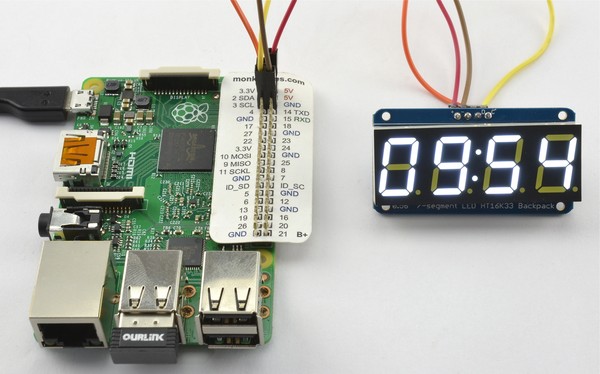
Figure 14-1. Seven-segment LED display with Raspberry Pi
To make this recipe, you need:
-
Four female-to-female jumper wires (see “Prototyping Equipment”)
-
Adafruit 4×7-segment LED with I2C backpack (see “Modules”)
The connections between the Raspberry Pi and the module are as follows:
- VCC (+) on the display to 5V on the Raspberry Pi GPIO connector
- GND (-) on the display to GND on the Raspberry Pi GPIO connector
- SDA (D) on the display to GPIO 2 (SDA) on the Raspberry Pi GPIO connector
- SCL (C) on the display to GPIO 3 (SCL) on the Raspberry Pi GPIO connector
Note that Adafruit also supplies a jumbo-sized LED display. This can be connected to the Raspberry Pi using the connections above, but the larger display has two positive power pins: one for the logic (V_IO) and one for the display (5V). You can just use an extra female-to-female jumper wire to connect this extra pin to the second 5V pin on the GPIO connector. This is because, being a large display, it requires more current for the LED display. Fortunately, the Raspberry Pi can supply enough power for it.
For this recipe to work, you will also need to set up your Raspberry Pi for I2C, so follow Recipe 9.3 first.
The display has an accompanying Python library written by Adafruit. It isn’t installed as a proper library, so to use it, you first need to download the folder structure.
$ git clone https://github.com/adafruit/Adafruit-Raspberry-Pi-Python-Code.git
Change directory into the Adafruit code by using:
$ cd Adafruit-Raspberry-Pi-Python-Code
$ cd Adafruit_LEDBackpack
In this folder, you will find a test program that will display the time. Run it by using the command:
$ sudo python ex_7segment_clock.py
Discussion
If you open the example file ex_7segment_clock.py in nano, you’ll see that the key commands are:
fromAdafruit_7SegmentimportSevenSegment
This imports the library code into your program. You then need to create a instance of SevenSegment using the next line of code. The address supplied as an argument is the I2C address (see Recipe 9.4).
Every I2C slave device has an address number. The LED board has three pairs of solder pads on the back that can be bridged with solder if you want to change the address. This is essential if you need to operate more than one I2C device from a single Raspberry Pi.
segment=SevenSegment(address=0x70)
To actually set the contents of a particular digit, use a line like this one:
segment.writeDigit(0,int(hour/10))
The first argument (0) is the digit position. Note that these positions are 0, 1, 3, and 4. Position 2 is reserved for the two dots in the center of the display.
The second argument is the number to display.
See Also
You can find out more about the Adafruit library at http://bit.ly/HQBE6W.
14.2 Displaying Messages on an I2C LED Matrix
Solution
Use an I2C LED module, such as the model shown in Figure 14-2, attached to a Raspberry Pi using female-to-female jumper wires.
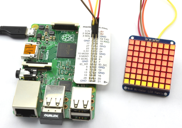
Figure 14-2. LED matrix display with Raspberry Pi
To make this recipe, you need:
-
Four female-to-female jumper wires (see “Prototyping Equipment”)
-
Adafruit bicolor LED square-pixel matrix with I2C backpack (see “Modules”)
The connections between the Raspberry Pi and the module are as follows:
- VCC (+) on the display to 5V on the Raspberry Pi GPIO connector
- GND (-) on the display to GND on the Raspberry Pi GPIO connector
- SDA (D) on the display to GPIO 2 (SDA) on the Raspberry Pi GPIO connector
- SCL (C) on the display to GPIO 3 (SCL) on the Raspberry Pi GPIO connector
For this recipe to work, you will also need to set up your Raspberry Pi for I2C, so follow Recipe 9.3 first.
The display has an accompanying Python library written by Adafruit. It’s not installed as a proper library, so to use it, you first need to download the folder structure.
$ git clone https://github.com/adafruit/Adafruit-Raspberry-Pi-Python-Code.git
Change directory into the Adafruit code by using:
$ cd Adafruit-Raspberry-Pi-Python-Code
$ cd Adafruit_LEDBackpack
In this folder, you will find a test program that displays the time as scrolling digits. Run it by using the command:
$ sudo python ex_8x8_color_pixels.py
Discussion
The program cycles through all the colors for each pixel in turn. The code is listed here, with some of the comments and an unnecessary import removed:
importtimefromAdafruit_8x8importColorEightByEightgrid=ColorEightByEight(address=0x70)iter=0# Continually update the 8x8 display one pixel at a timewhile(True):iter+=1forxinrange(0,8):foryinrange(0,8):grid.setPixel(x,y,iter%4)time.sleep(0.02)
The address supplied as an argument to the next line is the I2C address (see Recipe 9.4):
grid=ColorEightByEight(address=0x70)
Every I2C slave device has an address number. The LED board has three pairs of solder pads on the back that can be bridged with solder if you want to change the address. This is essential if you need to operate more than one I2C device with the same base address from a single Raspberry Pi.
The variable iter gets 1 added to it each time through the loop. The command grid.setPixel takes x and y coordinates as its first two parameters. The final parameter is the color to which the pixel will be set. This is a number between 0 and 3 (0 is off, 1 is green, 2 is red, and 3 is orange).
The variable iter is used to generate the number between 0 and 3 using the % operator, which is the modulo remainder (i.e., what is left over when you divide iter by 4).
See Also
You can find out more about this product at http://www.adafruit.com/products/902.
14.3 Using the Sense HAT LED Matrix Display
Solution
Follow Recipe 9.16 and install the software that the Sense HAT needs and then use the library commands to display text.
The program sense_hat_clock.py illustrates this by repeatedly displaying the date and time in a scrolling message. As with all the program examples in this book, you can also download the program from the Code section of the Raspberry Pi Cookbook website.
fromsense_hatimportSenseHatfromdatetimeimportdatetimeimporttimehat=SenseHat()time_color=(0,255,0)date_color=(255,0,0)whileTrue:now=datetime.now()date_message='{:%d%B %Y}'.format(now)time_message='{:%H:%M:%S}'.format(now)hat.show_message(date_message,text_colour=date_color)hat.show_message(time_message,text_colour=time_color)
Discussion
Two colors are defined so that the date and time parts of the message can be displayed in different colors. These colors are then used as an optional parameter to show_message.
Other optional parameters to show_message are:
scroll_speedwhich is actually the delay between each scrolling step rather than the speed. So a higher value makes the scrolling slower.back_coloursets the background color. Note the British spelling of “back_colour” with a “u.”
The display can be used for a lot more than just displaying scrolling text. Starting at its most basic, you can set individual pixels using set_pixel, set the orientation of the display using set_rotation, and display an image (albeit a small one) with load_image. The example below, which you can find in sense_hat_taster.py, illustrates these function calls. As with all the program examples in this book, you can also download the program from the Code section of the Raspberry Pi Cookbook website.
The image must be just 8×8 pixels, but most common graphics formats like .jpg and .png can be used and the bit depth will be handled automatically.
fromsense_hatimportSenseHatimporttimehat=SenseHat()red=(255,0,0)hat.load_image('small_image.png')time.sleep(1)hat.set_rotation(90)time.sleep(1)hat.set_rotation(180)time.sleep(1)hat.set_rotation(270)time.sleep(1)hat.clear()hat.set_rotation(0)forxyinrange(0,8):hat.set_pixel(xy,xy,red)hat.set_pixel(xy,7-xy,red)
Figure 14-3 shows the Sense HAT displaying a crude image.
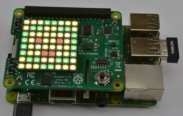
Figure 14-3. A Sense HAT displaying an “image”
See Also
For full documentation on the Sense HAT, see https://pythonhosted.org/sense-hat/api/.
For information on formatting dates and times, see Recipe 7.2.
Other recipes that use the Sense HAT are Recipes 9.16, 13.10, 13.13, 13.14, and 13.16.
14.4 Displaying Messages on an Alphanumeric LCD HAT
Solution
Use a Displayotron Pimoroni HAT attached to your Raspberry Pi as shown in Figure 14-4.
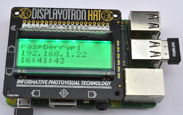
Figure 14-4. A Displayotron LCD HAT
This HAT requires both I2C and SPI to be enabled, so if you have not already done so, follow Recipe 9.3 and Recipe 9.5.
Then fetch the code for its accompanying library from GitHub and install it by using the following commands:
$ git clone https://github.com/pimoroni/dot3k.git
$ cd dot3k/python/library
$ sudo python setup.py install
By way of example, the following program (displayotron_ip.py) finds the hostname and IP address of your Raspberry Pi and displays them along with the time. If all is well, then the backlit LED will be green, but if the network connection is down, the backlight will turn red.
As with all the program examples in this book, you can also download the program from the Code section of the Raspberry Pi Cookbook website.
importdothat.lcdaslcdimportdothat.backlightasbacklightimporttimefromdatetimeimportdatetimeimportsubprocesswhileTrue:lcd.clear()backlight.rgb(0,255,0)try:hostname=subprocess.check_output(['hostname']).split()[0]ip=subprocess.check_output(['hostname','-I']).split()[0]t='{:%H:%M:%S}'.format(datetime.now())lcd.write(hostname)lcd.set_cursor_position(0,1)lcd.write(ip)lcd.set_cursor_position(0,2)lcd.write(t)except:backlight.rgb(255,0,0)time.sleep(1)
Discussion
The test program imports the necessary libraries, including subprocess (see Recipe 7.15), which will be used to find the IP address (see Recipe 2.2) of the Raspberry Pi and its hostname.
The main methods in the library are:
lcd.clearclears the display of any textlcd.set_cursor_positionsets the position for new text to be written to the column and row specified as its two parameterslcd.writeadds the text supplied as its parameter to the current cursor positionbacklight.rgbsets the red, green, and blue values of the backlight (0 to 255)
See Also
You can find out more about this HAT on PiMoroni’s product page.
To attach a low-cost LCD module directly to a Raspberry Pi without a HAT, see Recipe 14.5.
14.5 Displaying Messages on an Alphanumeric LCD Module
Solution
Use an HD44780-compatible LCD module and wire it to the GPIO connector.
This is clearly a lot more complex than using a ready-made shield, but, if you are planning a complex project where the display is one element and you need access to other GPIO pins, then it is useful to know how to use an LCD module directly.
You will find many low-cost LCD modules, such as the one shown connected to a Raspberry Pi in Figure 14-5. These have 16 pins, although fortunately, not all of them have to be connected to a GPIO pin.
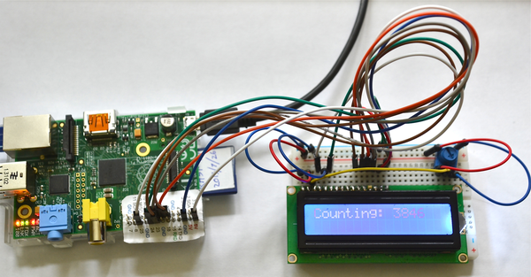
Figure 14-5. A 16×2 LCD display connected to a Raspberry Pi
These modules are available in a number of sizes and are specified by the number of columns and rows of letters they can display. So, for example, the module used in this recipe is described as 16×2 because it can display two rows each of 16 characters. Other common sizes are 8×1, 16×1, 16×2, 20×2, and 20×4.
To make this recipe, you will need:
-
Breadboard and jumper wires (see “Prototyping Equipment”)
-
16×2 HD44780-compatible LCD module (see “Modules”)
-
Row of 16 header pins (see “Miscellaneous”)
-
10kΩ trimpot (see “Resistors and Capacitors”)
Figure 14-6 shows the breadboard layout for connecting the display. The LCD modules are not normally supplied with header pins, so you will need to solder these in place.
The trimpot is used to control the contrast of the display. Note that if it looks like the project has not worked, try moving the knob of the trimpot over its entire range. It may well be that the contrast is so off that the display characters are not visible at all.
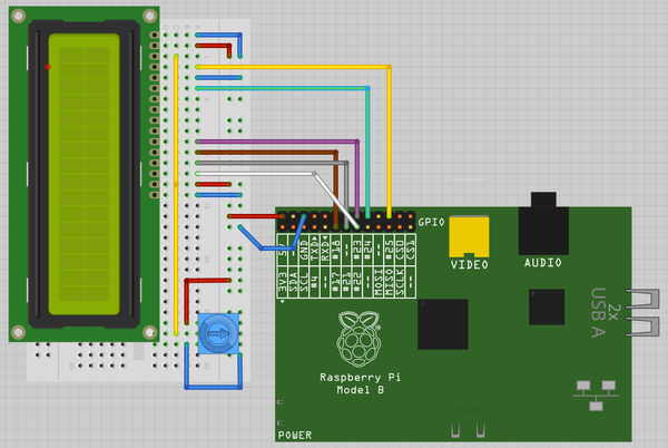
Figure 14-6. Wiring an LCD display to a Raspberry Pi
The Adafruit Raspberry Pi example code, available from GitHub, includes a library for controlling LCD displays that use the HD44780 driver. Before installing it, follow Recipe 9.2 to install the RPi.GPIO library.
The Adafruit library is not installed as a proper library, so to use it, you first need to download the folder structure.
$ git clone https://github.com/adafruit/Adafruit-Raspberry-Pi-Python-Code.git
Change directory into the one that holds the Adafruit code by using:
$ cd Adafruit-Raspberry-Pi-Python-Code
$ cd Adafruit_CharLCD
There is a test program here that displays the time and IP address of the Raspberry Pi. But first, if you are using a newer Raspberry Pi model B, revision 2, you will need to edit the file Adafruit_CharLCD.py:
$ nano Adafruit_CharLCD.py
Search for the line:
def__init__(self,pin_rs=25,pin_e=24,pins_db=[23,17,21,22],GPIO=None):
Replace the number 21 with 27 so that the line looks as follows, and then save and exit the file:
def__init__(self,pin_rs=25,pin_e=24,pins_db=[23,17,27,22],GPIO=None):
You can now run the example program with the command:
$ sudo python Adafruit_CharLCD_IPclock_example.py
Discussion
These displays can operate either with a four- or eight-bit data bus and also require three control pins. The pins are connected as per Table 14-1.
| LCD module pin | GPIO pin | Notes |
|---|---|---|
|
1 |
GND |
0V |
|
2 |
+5V |
5V logic supply |
|
3 |
No connection |
Contrast control voltage |
|
4 |
25 |
RS: Register select |
|
5 |
GND |
RW: Read/write (always write) |
|
6 |
24 |
EN: Enable |
|
7-10 |
No connection |
Only used in eight-bit mode |
|
11 |
23 |
D4: Data line 4 |
|
12 |
17 |
D5: Data line 5 |
|
13 |
21 |
D6: Data line 6 |
|
14 |
22 |
D7: Data line 7 |
|
15 |
+5V |
LED backlight |
|
16 |
GND |
LED backlight |
The Adafruit library file Adafruit_CharLCD.py is responsible for setting the values on the data pins and then sending them to the display module. It provides the following functions, which you can use in your programs:
home()-
Move to top left.
clear()-
Clear all text off the display.
setCursor(column, row)-
Set the cursor position from where text will be written.
cursor()-
Turn on cursor display.
noCursor()-
Turn off cursor display (default).
message(text)-
Write the text at the current cursor position.
The following minimal example program shows how easy it is to display a simple message by using the library:
fromAdafruit_CharLCDimportAdafruit_CharLCDfromtimeimportsleeplcd=Adafruit_CharLCD()lcd.begin(16,2)i=0whileTue:lcd.clear()lcd.message('Counting: '+str(i))sleep(1)i=i+1
See Also
This recipe is based on the Adafruit tutorial at the Adafruit learning website. Adafruit also sells a plug-in board with an LCD display attached that is compatible with this recipe.
For the convenience of using a ready-made alphanumeric LCD display on a HAT, see Recipe 2.2.
14.6 Using an OLED Graphical Display
Solution
Use an OLED display based on the SSD1306 driver chip, using an I2C interface (Figure 14-7).
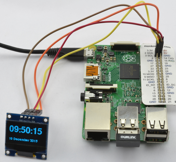
Figure 14-7. An I2C OLED display
To make this recipe, you need:
-
Four female-to-female jumper wires (see “Prototyping Equipment”)
-
I2C OLED display 128×64 pixels (see “Modules”)
Some of these displays have just four pins, whereas others have eight pins. The 8-pin varieties (including Adafruit’s displays) have more pins because they have both an I2C and SPI interfaces. The 4-pin displays just have an I2C. The I2C interface is better suited for use with the Raspberry Pi because the display operates at 5V, and both interface pins for I2C (SDA and SCL) are 3.3V outputs from the Raspberry Pi, whereas the SPI interface’s MISO pin is a 3.3V input that requires level conversion before connecting to the Raspberry Pi.
The connections between the Raspberry Pi and the module are as follows:
- VCC on the display to 5V on the Raspberry Pi GPIO connector
- GND on the display to GND on the Raspberry Pi GPIO connector
- SDA on the display to GPIO 2 (SDA) on the Raspberry Pi GPIO connector
- SCL on the display to GPIO 3 (SCL) on the Raspberry Pi GPIO connector
For this recipe to work, you will also need to set up your Raspberry Pi for I2C, so follow Recipe 9.3 first.
Adafruit has a library for these displays. Install it by using these commands:
$ git clone https://github.com/adafruit/Adafruit_Python_SSD1306.git
$ cd Adafruit_Python_SSD1306
$ sudo python setup.py install
This library uses the Python Image Library (PIL), which can be installed by using the command:
$ sudo pip install pillow
The code example old_clock.py displays the time and date on the OLED display. As with all the program examples in this book, you can also download the program from the Code section of the Raspberry Pi Cookbook website.
fromoled.deviceimportssd1306fromoled.renderimportcanvasfromPILimportImageFontimporttimefromdatetimeimportdatetime# Set up displaydevice=ssd1306(port=1,address=0x3C)font_file='/usr/share/fonts/truetype/freefont/FreeSansBold.ttf'small_font=ImageFont.truetype('FreeSans.ttf',12,filename=font_file)large_font=ImageFont.truetype('FreeSans.ttf',33,filename=font_file)# Display a message on 3 lines, first line big fontdefdisplay_message(top_line,line_2):globaldevicewithcanvas(device)asdraw:draw.text((0,0),top_line,font=large_font,fill=255)draw.text((0,50),line_2,font=small_font,fill=255)whileTrue:now=datetime.now()date_message='{:%d%B %Y}'.format(now)time_message='{:%H:%M:%S}'.format(now)display_message(time_message,date_message)time.sleep(0.1)
Every I2C slave device has an address, which is set in the line:
device=ssd1306(port=1,address=0x3C)
This is fixed at 3C (hex) for many of the low-cost I2C modules but may vary, so you should check any documentation that comes with the device or use I2C tools (Recipe 9.4) to list all the I2C devices attached to the bus so that you can see the address of your display.
Discussion
Small, organic LED (OLED) displays are cheap, don’t use much current, and have high resolution despite their diminutive size. They are replacing LCD displays in many consumer products.
See Also
The instructions here are for 4-pin I2C interfaces. If you really want to use the SPI interface, then take a look at Adafruit’s tutorial on this.
14.7 Using Addressable RGB LED Strips
Solution
Use an LED strip based on the WS2812 RGB LED chips on your Raspberry Pi.
Using these LED strips (Figure 14-8) can be really easy, with a direct connection to the Raspberry Pi and power for the LEDs supplied by the Raspberry Pi. This is the “Happy Day” scenario that should work just fine, but do see the Discussion for this recipe for potential pitfalls with this approach and ways to guarantee that your LED strip use is trouble-free.
Don’t Power the LEDS from the Pi’s 3.3V Supply
While it might be tempting to power the LEDs from the 3.3V supply pin on the GPIO connector, do not do this—it can only supply low currents (see Recipe 9.2). Using this pin could easily damage your Raspberry Pi.
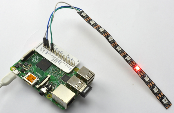
Figure 14-8. An LED strip of 10 LEDs
The LED strip used in Figure 14-8 is cut from a reel. In this case, there are 10 LEDs. As each LED can use up to 60mA, 10 is probably a sensible limit for the number of LEDs that can be used without arranging for a separate power supply for the LED strip (see Discussion).
To connect the strip to the Raspberry Pi, jumper wires with female connectors on one end were cut and the wire ends soldered to the three connections on the LED strip: GND, DI (Data In), and 5V. These can then be attached to GPIO pins GND, GPIO 18, and 5V, respectively.
Notice that the LED strip has an arrow printed on it (Figure 14-9). Make sure that when you solder leads to the LED strip, you start from the cut end to the left of the arrow.
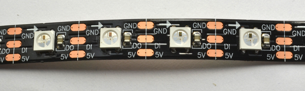
Figure 14-9. An LED strip close-up
Finding a library for the WS2812 that works with all Raspberry Pi models is, at the time of writing, a little tricky. The original library was developed by Jeremy Garff, and Raspberry Pi 2 support was added to this by Richard Hurst. Adafruit also had a hand in the library. However, Raspbian’s switch to Linux Kernel 4.1.6 broke a few things. At the time of writing, the Pimoroni Unicorn HAT (which uses a modified version of Richard Hurst’s library) seems to be most reliable. Being tied to a commercial product, this version is most likely to be maintained for any future changes to Raspbian or Raspberry Pi boards. To install this library, run the following commands:
$ git clone https://github.com/pimoroni/unicorn-hat.git
$ cd unicorn-hat/python/rpi-ws281x
$ make
$ sudo python setup.py install
The following example program (led_strip.py) will set the LED red in successive positions along the strip. As with all the program examples in this book, you can also download the program from the Code section of the Raspberry Pi Cookbook website.
importtimefromneopixelimport*# LED strip configuration:LED_COUNT=10# Number of LED pixels.LED_PIN=18# GPIO pin connected to the pixels (must support PWM!).LED_FREQ_HZ=800000# LED signal frequency in hertz (usually 800khz)LED_DMA=5# DMA channel to use for generating signal (try 5)LED_BRIGHTNESS=255# Set to 0 for darkest and 255 for brightestLED_INVERT=False# True to invert the signalRED=Color(255,0,0)NO_COLOR=Color(0,0,0)strip=Adafruit_NeoPixel(LED_COUNT,LED_PIN,LED_FREQ_HZ,LED_DMA,LED_INVERT,LED_BRIGHTNESS)strip.begin()defclear():foriinrange(0,LED_COUNT):strip.setPixelColor(i,NO_COLOR)strip.show()i=0whileTrue:clear()strip.setPixelColor(i,RED)strip.show()time.sleep(1)i+=1ifi>=LED_COUNT:i=0
The parameters in the section LED strip configuration can be modified for different LED configurations. If you have a different number of LEDs in your strip, then modify LED_COUNT. The rest of the constants do not need to be changed.
Each of the LEDs can have its color set independently using the setPixelColor method. The first parameter to this is the index position (starting at 0) of the LED whose color you want to set. The second parameter is the color to set it to. The changes to the LED colors are not actually updated until the method show is called.
Discussion
Each LED in the strip can use a maximum of about 60mA. It will only do this if all three color channels (red, green, and blue) are at maximum brightness (255). So, if you plan to use a lot of LEDs, then you will need to use a separate 5V power supply sufficient to supply all the LEDs in your strip. Figure 14-10 shows how you would wire up a separate power supply. A female DC jack-to-screw terminal adapter (“Prototyping Equipment”) makes it easy to connect an external power supply to a breadboard.
The datasheet for the WS2812 states that the input signal should have a logic high of at least 4V for a 5V power supply to the LEDs. So, when using this with a Raspberry Pi’s 3.3V GPIO output, there are no guarantees that the LEDs will work reliably. Having said that, I have never had any trouble.
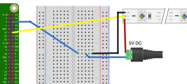
Figure 14-10. Powering an LED strip with an external power supply
If you do have problems with the signal not being strong enough, you can use a single transistor logic-level converter as shown in Figure 14-11. A suitable transistor is the 2N7000 (note that a 2N3904 will not work in this situation as it cannot respond quickly enough to invert the pulses).
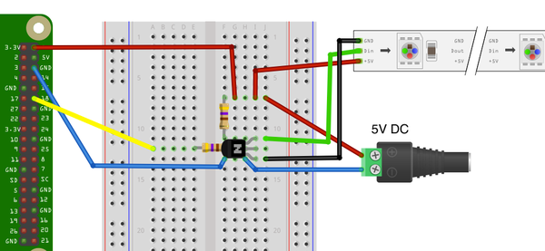
Figure 14-11. Using a logic-level converter
This transistor converts the 3.3V signal to 5V but has the side effect of inverting the signal, so if the output of the GPIO pin is HIGH, the signal into the LED strip will be LOW and vice-versa. This means that the logic in your program will need to be modified by changing the line:
LED_INVERT=False
to read:
LED_INVERT=True
See Also
An alternative to using a transistor to raise the signal level from 3.3V to 5V is to use a level converter module (see Recipe 9.13).
The Unicorn HAT, whose library is used here, has 64 WS2812 LEDs arranged in an 8×8 grid. You can find out more about this display at https://shop.pimoroni.com/products/unicorn-hat.